Boeing 737 - 600/700/800/900. Operations Manual (1997 year) - page 26
Air Systems -
Table of Contents
Boeing 737 Operations Manual
Flight Deck
2.30.4
Passenger Cabin
2.30.4
Recirculation Fan
2.30.4
Equipment Cooling
2.30.4
Forward Cargo Compartment
2.30.5
Conditioned Air Source Connection
2.30.5
Air Conditioning Distribution Schematic
2.30.6
Air Conditioning System Description
2.31.1
Introduction
2.31.1
Air Conditioning Pack
2.31.1
Airflow Control
2.31.1
Ram Air System
2.31.2
Cooling Cycle
2.31.2
Pack Temperature Control
2.31.2
Air Conditioning Pack Schematic
2.31.3
Zone Temperature Control
2.31.4
Zone Temperature Control Modes
2.31.4
Unbalanced Pack Temperature Control Mode
2.31.4
Standby Pack Average Temperature
2.31.5
Fixed Cabin Temperature
2.31.5
Air Conditioning Distribution
2.31.5
Flight Deck
2.31.5
Passenger Cabin
2.31.5
Recirculation Fan
2.31.6
Equipment Cooling
2.31.6
Forward Cargo Compartment
2.31.6
Conditioned Air Source Connection
2.31.6
Air Conditioning Distribution Schematic
2.31.7
Pressurization System Description
2.40.1
Introduction
2.40.1
Pressure Relief Valves
2.40.1
Cabin Pressure Controller
2.40.1
2.TOC.0.2
Air Systems -
Table of Contents
Boeing 737 Operations Manual
Cabin Pressure Control System Schematic
2.40.2
Pressurization Outflow
2.40.2
Outflow Valve
2.40.3
Overboard Exhaust Valve
2.40.3
Pressurization Outflow Schematic
2.40.4
Auto Mode Operation
2.40.5
High Altitude Landing
2.40.6
Flight Path Events - Auto Mode
2.40.7
Manual Mode Operation
2.40.8
2.TOC.0.3
Air Systems -
Table of Contents
Boeing 737 Operations Manual
Intentionally
Blank
2.TOC.0.4
Boeing 737 Operations Manual
Air Systems
Chapter 2
Controls and Indicators
Section 10
Bleed Air Controls and Indicators
[737 - 600/700]
DUAL
RAM DOOR
RAM DOOR
1
BLEED
FULL OPEN
FULL OPEN
RECIRC FAN
OFF
AUTO
6
60
80
DUCT
OVHT
40
PRESS
PSI
7
20
0
2
TEST
L PACK
R PACK
ISOLATION
OFF
OFF
VALVE
AUTO
AUTO
HIGH
CLOSE
HIGH
AUTO
WING
PACK
PACK
WING
ANTI
TRIP OFF
OPEN
TRIP OFF
ANTI
ICE
ICE
WING-BODY
TRIP
WING-BODY
3
OVERHEAT
OVERHEAT
BLEED
BLEED
TRIP OFF
TRIP OFF
8
RESET
9
OFF
OFF
ON
ON
4
1
APU
2
5
BLEED
FORWARD OVERHEAD PANEL
2.10.1
Air Systems -
Controls and Indicators
Boeing 737 Operations Manual
[737 - 800/900]
DUAL
RAM DOOR
RAM DOOR
1
BLEED
FULL OPEN
FULL OPEN
L RECIRC FAN
R RECIRC FAN
OFF
OFF
AUTO
AUTO
6
60
80
DUCT
OVHT
40
PRESS
PSI
7
20
0
2
TEST
L PACK
R PACK
ISOLATION
OFF
OFF
VALVE
AUTO
AUTO
HIGH
CLOSE
HIGH
AUTO
WING
WING
ANTI
PACK
OPEN
PACK
ANTI
ICE
ICE
WING-BODY
TRIP
WING-BODY
3
OVERHEAT
OVERHEAT
BLEED
BLEED
TRIP OFF
TRIP OFF
8
RESET
9
OFF
OFF
ON
ON
4
1
APU
2
5
BLEED
FORWARD OVERHEAD PANEL
1
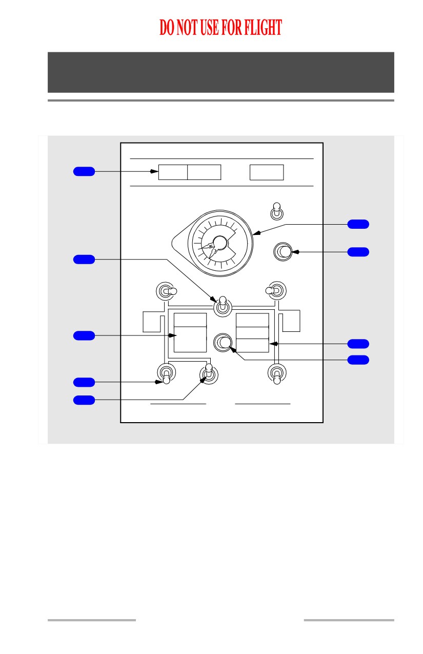
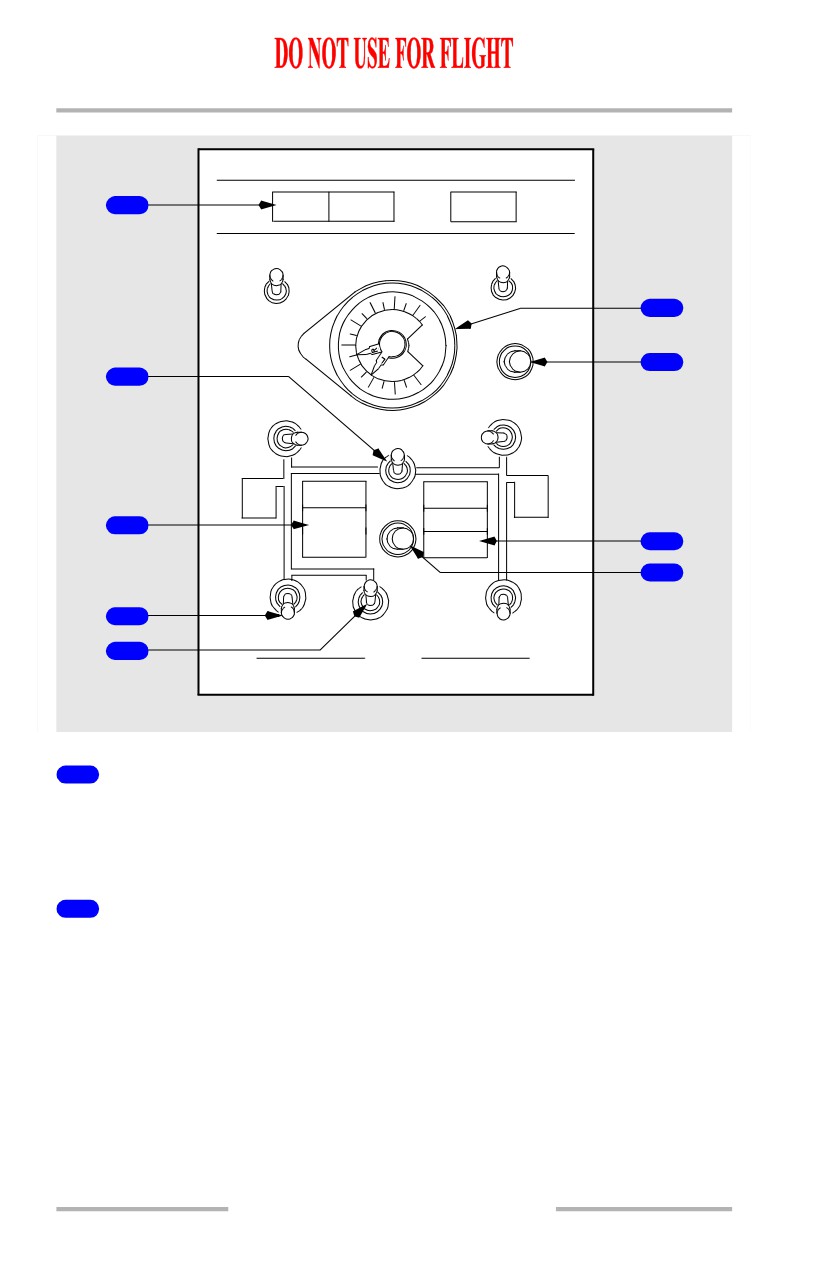
DUAL BLEED Light
Illuminated (amber) - APU bleed air valve open and engine No. 1 BLEED air
switch ON, or engine No. 2 BLEED air switch ON, APU bleed air valve and
isolation valve open.
2
ISOLATION VALVE Switch
CLOSE - closes isolation valve.
AUTO -
• closes isolation valve if both engine BLEED air switches are ON and both
air conditioning PACK switches are AUTO or HIGH
• opens isolation valve automatically if either engine BLEED air or air
conditioning PACK switch positioned OFF.
OPEN - opens isolation valve.
2.10.2
Air Systems -
Controls and Indicators
Boeing 737 Operations Manual
3
WING-BODY OVERHEAT Light
Illuminated (amber) -
• left light indicates overheat from bleed air duct leak in left engine strut,
left inboard wing leading edge, left air conditioning bay, keel beam or
APU bleed air duct
• right light indicates overheat from bleed air duct leak in right engine strut,
right inboard wing leading edge or right air conditioning bay.
4
Engine BLEED Air Switches
OFF - closes engine bleed air valve.
ON - opens engine bleed air valve when engines are operating.
5
APU BLEED Air Switch
OFF - closes APU bleed air valve.
ON - opens APU bleed air valve when APU is operating.
6
Bleed Air DUCT PRESSURE Indicator
Indicates pressure in L and R (left and right) bleed air ducts.
7
Wing-Body Overheat (OVHT) TEST Switch
Push -
• tests wing-body overheat detector circuits
• illuminates both WING-BODY OVERHEAT lights.
8
BLEED TRIP OFF Light
Illuminated (amber) - excessive engine bleed air temperature or pressure
• related engine bleed air valve closes automatically
• requires reset.
9
TRIP RESET Switch
[737 - 600/700]
Push (if fault condition is corrected) -
• resets BLEED TRIP OFF, PACK TRIP OFF and DUCT OVERHEAT
lights
• lights remain illuminated until reset.
2.10.3
Air Systems -
Controls and Indicators
Boeing 737 Operations Manual
9
TRIP RESET Switch
[737 - 800/900]
Push (if fault condition is corrected) -
• resets BLEED TRIP OFF, PACK and ZONE TEMP lights
• related engine bleed valve opens, or related pack valve opens, or related
air mix valve opens
• lights remain illuminated until reset.
2.10.4
Air Systems -
Controls and Indicators
Boeing 737 Operations Manual
Air Conditioning Controls and Indicators
[737 - 600/700 and Air Temperature Indicator in degrees C]]
CONT CABIN
AIR TEMP
PASS CABIN
SUPPLY
PASS
DUCT
CABIN
1
AIR MIX
AIR MIX
VALVE
VALVE
6
40
60
TEMP
DUCT
80
DUCT
2
OVERHEAT
OVERHEAT
20
100
0
`C
7
AUTO
AUTO
COOL
WARM
COOL
WARM
COOL
WARM
COOL
WARM
MANUAL
MANUAL
3
DUAL
RAM DOOR
RAM DOOR
BLEED
FULL OPEN
FULL OPEN
4
RECIRC FAN
OFF
8
AUTO
60
80
DUCT
OVHT
40
PRESS
PSI
20
0
TEST
L PACK
ISOLATION
R PACK
OFF
OFF
VALVE
AUTO
AUTO
5
CLOSE
HIGH
HIGH
AUTO
9
WING
PACK
PACK
WING
ANTI
TRIP OFF
OPEN
TRIP OFF
ANTI
ICE
ICE
WING-BODY
TRIP
WING-BODY
OVERHEAT
OVERHEAT
BLEED
BLEED
TRIP OFF
TRIP OFF
RESET
10
OFF
OFF
ON
ON
1
APU
2
BLEED
FORWARD OVERHEAD PANEL
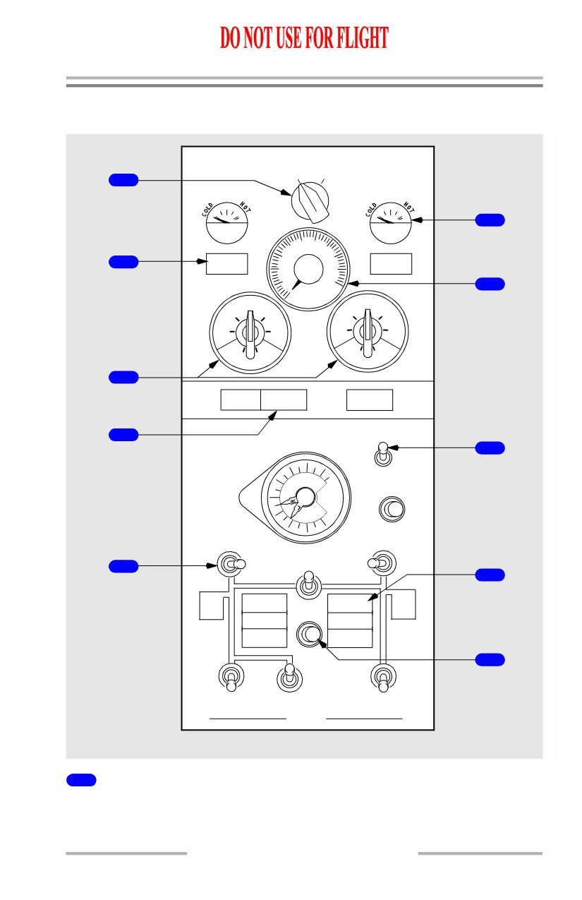
1
AIR Temperature (TEMP) Source Selector
SUPPLY DUCT - selects main distribution supply duct
sensor
for
TEMP
indicator.
2.10.5
Air Systems -
Controls and Indicators
Boeing 737 Operations Manual
PASS CABIN - selects passenger cabin sensor for TEMP indicator.
2
DUCT OVERHEAT Light
Illuminated (amber) -
• bleed air temperature in related duct exceeds limit
• air mix valves drive full cold
• requires reset.
3
Control (CONT) CABIN and Passenger (PASS) CABIN Temperature
Selector
AUTO - automatic temperature controller controls passenger cabin or flight deck
temperature as selected.
MANUAL - air mix valves controlled manually. Automatic temperature
controller bypassed.
4
RAM DOOR FULL OPEN Light
Illuminated (blue) - indicates ram door in full open position.
5
Air Conditioning PACK Switch
OFF - pack signalled OFF.
AUTO -
• with both packs operating, each pack regulates to low flow
• with one pack operating, operating pack regulates to high flow in flight
with flaps up
• when operating one pack from APU (both engine BLEED air switches
OFF), regulates to high flow.
HIGH -
• pack regulates to high flow
• provides maximum flow rate on ground with APU BLEED air switch ON.
6
AIR MIX VALVE Indicator
Indicates position of air mix valves:
• controlled automatically with related temperature selector in AUTO
• controlled manually with related temperature selector in MANUAL.
7
Air Temperature (TEMP) Indicator
Indicates temperature at location selected with AIR TEMP source selector.
2.10.6
Air Systems -
Controls and Indicators
Boeing 737 Operations Manual
8
Recirculation (RECIRC) FAN Switch
OFF - fan signalled off.
AUTO - fan signalled on except when both packs operating with either PACK
switch in HIGH.
9
PACK TRIP OFF Light
Illuminated (amber) -
• indicates pack temperature has exceeded limits
• related pack valve automatically closes and mix valves drive full cold
• requires reset.
10
TRIP RESET Switch
Push (if fault condition is corrected) -
• resets BLEED TRIP OFF, PACK TRIP OFF and DUCT OVERHEAT
lights
• related engine bleed air valves open, or related pack valves open, or
related air mix valves open
• lights remain illuminated until reset.
October 15, 2001
2.10.7
Air Systems -
Controls and Indicators
Boeing 737 Operations Manual
[737 - 800/900 and Air Temperature Indicator in degrees F]
AIR TEMP
PASS
CAB
120MP1.
60
S
FWD
U
D
AFT
AFT
80
1
200
P
U
F
6
P
C
W
R
P
40
F
L
T
D
A
Y
CONT
L
C
TRIM AIR
CAB
K
OFF
7
ON
2
ZONE
ZONE
ZONE
TEMP a
TEMP a
TEMP a
CONT CAB
FWD CAB
AFT CAB
AUTO
AUTO
AUTO
3
C
W
C
W
C
W
OFF
OFF
OFF
DUAL
RAM DOOR
RAM DOOR
BLEED
FULL OPEN
FULL OPEN
4
8
L RECIRC FAN
R RECIRC FAN
OFF
OFF
AUTO
AUTO
60
80
DUCT
OVHT
40
PRESS
PSI
20
0
TEST
L PACK
R PACK
ISOLATION
OFF
VALVE
OFF
AUTO
AUTO
5
CLOSE
HIGH
HIGH
AUTO
9
WING
WING
PACK
OPEN
PACK
ANTI
ANTI
ICE
ICE
WING-BODY
TRIP
WING-BODY
OVERHEAT
OVERHEAT
BLEED
BLEED
TRIP OFF
TRIP OFF
RESET
10
OFF
OFF
ON
ON
1
APU
2
BLEED
FORWARD OVERHEAD PANEL
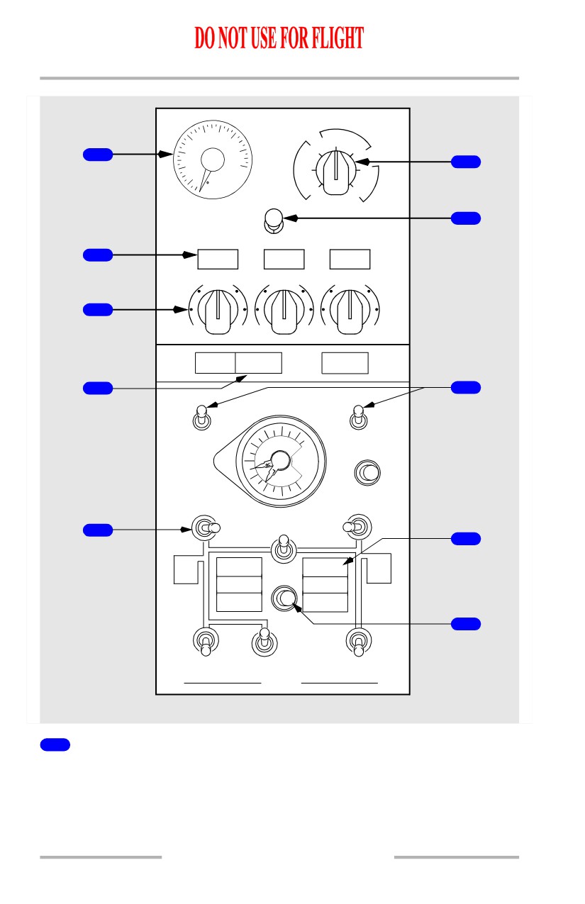
1
Air Temperature (TEMP) Indicator
Indicates temperature at location selected with AIR TEMP source selector.
2.10.8
Air Systems -
Controls and Indicators
Boeing 737 Operations Manual
2
ZONE TEMP Lights
Illuminated (amber) -
• CONT CAB indicates a duct temperature overheat or failure of the flight
deck primary and standby temperature control
• FWD CAB or AFT CAB indicates duct temperature overheat.
During Master Caution light recall:
• CONT CAB indicates failure of the flight deck primary or standby
temperature control
• either FWD CAB or AFT CAB indicates failure of the associated zone
temperature control
• lights will extinguish when Master Caution is reset.
3
Temperature Selector
AUTO - provides automatic temperature control for the associated zones.
Rotating the control toward C (cool) or W (warm) manually sets the desired
temperature.
OFF - closes the associated trim air modulating valve.
4
RAM DOOR FULL OPEN Light
Illuminated (blue) - indicates ram door in full open position.
5
Air Conditioning PACK Switch
OFF - pack signalled OFF.
AUTO -
• with both packs operating, each pack regulates to low flow
• with one pack operating, operating pack regulates to high flow in flight
with flaps up
• when operating one pack from APU (both engine BLEED air switches
OFF), regulates to high flow.
HIGH -
• pack regulates to high flow
• provides maximum flow rate on ground with APU BLEED air switch ON.
6
AIR Temperature (TEMP) Source Selector
SUPPLY DUCT - selects appropriate zone supply duct temperature
PASS CAB - selects forward or aft passenger cabin temperature
PACK - selects left or right pack temperatures.
2.10.9
Air Systems -
Controls and Indicators
Boeing 737 Operations Manual
7
TRIM AIR Switch
ON - trim air pressure regulating and shutoff valve signaled open.
OFF - trim air pressure regulating and shutoff valve signaled closed.
8
Recirculation (RECIRC) FAN Switches
OFF - fan signalled off.
AUTO -
• in-flight -
• the left recirculation fan operates if both packs are operating unless
either PACK switch is in HIGH
• the right recirculation fan operates if both packs are operating unless
both PACK switches are in HIGH.
• on the ground -
• the left recirculation fan operates unless both PACK switches are in
HIGH
• the right recirculation fan operates even if both PACK switches are in
HIGH.
9
PACK Light
Illuminated (amber) -
• indicates pack trip off or failure of both primary and standby pack
controls
• during Master Caution recall, indicates failure of either primary or
standby pack control. Extinguishes when Master Caution is reset
10
TRIP RESET Switch
Push (if fault condition is corrected) -
• resets BLEED TRIP OFF, PACK and ZONE TEMP lights
• lights remain illuminated until reset.
2.10.10
Air Systems -
Controls and Indicators
Boeing 737 Operations Manual
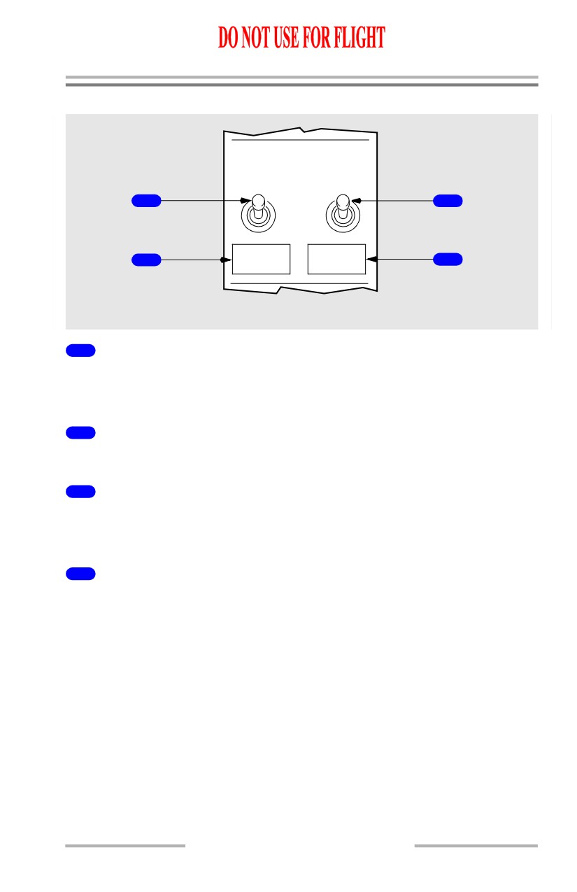
Equipment Cooling Panel
EQUIP COOLING
SUPPLY
EXHAUST
NORM
1
3
ALTN
2
OFF
OFF
4
FORWARD OVERHEAD PANEL
1
Equipment (EQUIP) COOLING SUPPLY Switch
NORM - normal cooling supply fan activated.
ALTN - alternate cooling supply fan activated.
2
Equipment Cooling Supply OFF Light
Illuminated (amber) - no airflow from selected cooling supply fan.
3
Equipment (EQUIP) COOLING EXHAUST Switch
NORM - normal cooling exhaust fan activated.
ALTN - alternate cooling exhaust fan activated.
4
Equipment Cooling Exhaust OFF Light
Illuminated (amber) - no airflow from selected cooling exhaust fan.
2.10.11
Air Systems -
Controls and Indicators
Boeing 737 Operations Manual
Cabin Altitude Panel
[Option - High Altitude Landing switch]
0
ALT
10
1
HORN
0
50
CUTOUT
9
2
40
CABIN
ALT
5
35
3
1
30
8
3
X 1000 FEET
10
25
20
15
7
4
HIGH
ALT LDG
6
5
ON
4
PRESS DIFF
LIMIT:TAKE-
INOP
5
OFF & LDG
1
2
.125 PSI
.5
3
UP
2
0
4
DN
T
3
.5
2
1
FORWARD OVERHEAD PANEL
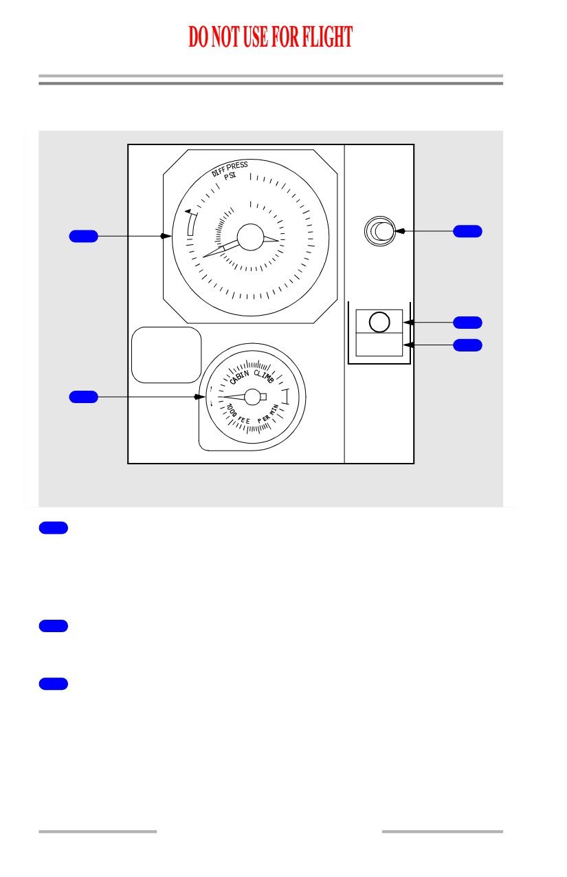
1
CABIN Altimeter (ALT)/Differential Pressure (DIFF PRESS)
Indicator
Inner Scale - indicates cabin altitude in feet.
Outer Scale - indicates differential pressure between cabin and ambient in psi.
2
CABIN Rate of CLIMB Indicator
Indicates cabin rate of climb or descent in feet per minute.
3
Altitude (ALT) HORN CUTOUT Switch
Push -
• cuts out intermittent cabin altitude warning horn
• altitude warning horn sounds when cabin reaches 10,000 feet altitude.
2.10.12
Air Systems -
Controls and Indicators
Boeing 737 Operations Manual
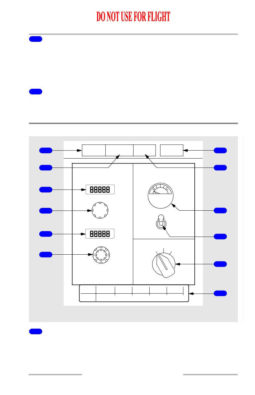
4
High Altitude Landing Switch
[Option - High Altitude Landing switch]
Off - (ON not visible)
• reprograms cabin pressurization from high altitude to normal operation
• extinguishes INOP light
5
High Altitude Landing INOP Light
[Option - High Altitude Landing switch]
Illuminated (amber) - indicates high altitude landing system fault.
Cabin Pressurization Panel
AUTO
OFF SCHED
1
ALTN
MANUAL
7
FAIL
DESCENT
2
8
AUTO
MANUAL
V
3
A
L
FLT ALT
V
E
4
C
9
O
L
P
O
E
S
N
5
E
10
LAND ALT
ALTN
AUTO
MAN
6
11
CAB ALT
LAND ALT
2000
4000
6000
8000
12
FLT ALT
<FL160 FL220 FL260 FL320 FL410
FORWARD OVERHEAD PANEL
1
AUTO FAIL Light
Illuminated (amber) - automatic pressurization system failure detected:
• indicates a single controller failure when ALTN light is also illuminated
• indicates a dual controller failure when illuminated alone.
2.10.13
Air Systems -
Controls and Indicators
Boeing 737 Operations Manual
2
OFF Schedule (SCHED) DESCENT Light
Illuminated (amber) - airplane descended before reaching the planned cruise
altitude set in the FLT ALT indicator.
3
Flight Altitude (FLT ALT) Indicator
• indicates selected cruise altitude
• set before takeoff.
4
Flight Altitude Selector
Rotate - set planned cruise altitude.(-1,000 ft. to 42,000 ft. in 500 ft. increments).
5
Landing Altitude (LAND ALT) Indicator
• indicates altitude of intended landing field
• set before takeoff.
6
Landing Altitude Selector
Rotate - select planned landing field altitude. (-1,000 ft. to 14,000 ft. in 50 ft.
increments).
7
MANUAL Light
Illuminated (green) - pressurization system operating in the manual mode.
8
Alternate (ALTN) Light
Illuminated (green) - pressurization system operating in the alternate automatic
mode:
• Illumination of both ALTN and AUTO FAIL lights indicates a single
controller failure and automatic transfer to ALTN mode
• pressurization mode selector in ALTN position.
9
Outflow VALVE Position Indicator
• indicates position of outflow valve
• operates in all modes.
10
Outflow Valve Switch (spring-loaded to center)
CLOSE - closes outflow valve electrically with pressurization mode selector in
MAN position.
OPEN - opens outflow valve electrically with pressurization mode selector in
MAN position.
2.10.14
Air Systems -
Controls and Indicators
Boeing 737 Operations Manual
11
Pressurization Mode Selector
AUTO - pressurization system controlled automatically.
ALTN - pressurization system controlled automatically using ALTN controller.
MAN -
• pressurization system controlled manually by outflow valve switch
• both auto controllers bypassed.
12
Cabin /Flight Altitude (CAB ALT)(FLT ALT) Placard
Used to determine setting for cabin altitude when operating in manual mode.
2.10.15
Air Systems -
Controls and Indicators
Boeing 737 Operations Manual
Intentionally
Blank
2.10.16
Boeing 737 Operations Manual
Air Systems
Chapter 2
Bleed Air System Description
Section 20
Introduction
Air for the bleed air system can be supplied by the engines, APU, or an external
air cart/source. The APU or external cart supplies air to the bleed air duct prior to
engine start. After engine start, air for the bleed air system is normally supplied by
the engines.
The following systems rely on the bleed air system for operation:
• Air conditioning/pressurization
• Wing and engine thermal anti-icing
• Engine starting
• Hydraulic reservoirs pressurization
• Water tank pressurization
[Option - Aspirated TAT]
• Aspirated TAT probe
Switches on the air conditioning panel operate the APU and engine bleed air
supply system.
Engine Bleed System Supply
Engine bleed air is obtained from the 5th and 9th stages of the compressor section.
When 5th stage low pressure bleed air is insufficient for the bleed air system
requirements, the high stage valve modulates open to maintain adequate bleed air
pressure. During takeoff, climb, and most cruise conditions, low pressure bleed air
from the 5th stage is adequate and the high stage valve remains closed.
Engine Bleed Air Valves
The engine bleed air valve acts as a pressure regulator and shutoff valve. With the
engine bleed air switch ON, the valve is DC activated and pressure operated. The
valve maintains proper system operating pressure and reduces bleed air outflow in
response to high bleed air temperature.
Bleed Trip Sensors
Bleed trip sensors illuminate the respective BLEED TRIP OFF light when engine
bleed air temperature or pressure exceeds a predetermined limit. The respective
engine bleed air valve closes automatically.
2.20.1