Kubota tractor (BX25DLB-AU, LA240A, LA240A, AU-SG, BT602). OPERATOR'S MANUAL - part 20


  Index      Tractors     Kubota tractor (BX25DLB-AU, LA240A, LA240A, AU-SG, BT602). OPERATOR'S MANUAL


Search            copyright infringement  


Content   ..  18  19  20  21   ..


Kubota tractor (BX25DLB-AU, LA240A, LA240A, AU-SG, BT602). OPERATOR'S MANUAL - part 20


49

HYDRAULIC UNIT

HYDRAULIC UNIT

3-POINT HITCH CONTROL SYSTEM

To avoid personal injury:
A

Before using the 3-point hitch controls, ensure
that no person or object is in the area of the
implement or 3-point hitch. Do not stand on or
near the implement or between the implement
and tractor when operating the 3-point hitch
controls.

B

Hydraulic Control

Operating the hydraulic control lever actuates the
hydraulic lift arm, which controls the elevation of 3-point
hitch mounted implement.
To lower implement, move the hydraulic control lever
forward; to raise it, move the hydraulic control lever
rearward.
The positions (B) and (C) of the lever in contact with the
inner stopper enables you to control the valve with ease in
increments of approximately 6.4 mm at the lower link end.

A

If the 3-point hitch can not be raised by setting the
hydraulic control lever to the "UP" position after long
term storage or when changing the transmission oil,
follow these air bleeding procedures.
(1) Stop the engine.
(2) Set the hydraulic control lever to the down

position and start the engine.

(3) Operate the engine at low idle speed for at least

30 seconds to bleed air from the system.

A

Do not operate until the engine is warmed up. If
operation is attempted when the engine is still cold, the
hydraulic system may be damaged.

A

If noises are heard when implement is lifting after the
hydraulic control lever has been activated, the
hydraulic mechanism is not adjusted properly.
Unless corrected the unit will be damaged.
Contact your KUBOTA Dealer for adjustment.

B

3-point Hitch Lowering Speed

To avoid personal injury:
A

Fast lowering speed may cause damage or
injury. Lowering speed of implement should be
adjusted to 2 or more seconds.

The lowering speed of the 3-point hitch can be controlled
or locked in similar fashion to a water faucet, turn toward
(A) to increase, (B) to reduce and (C) firmly to the stop for
lock.

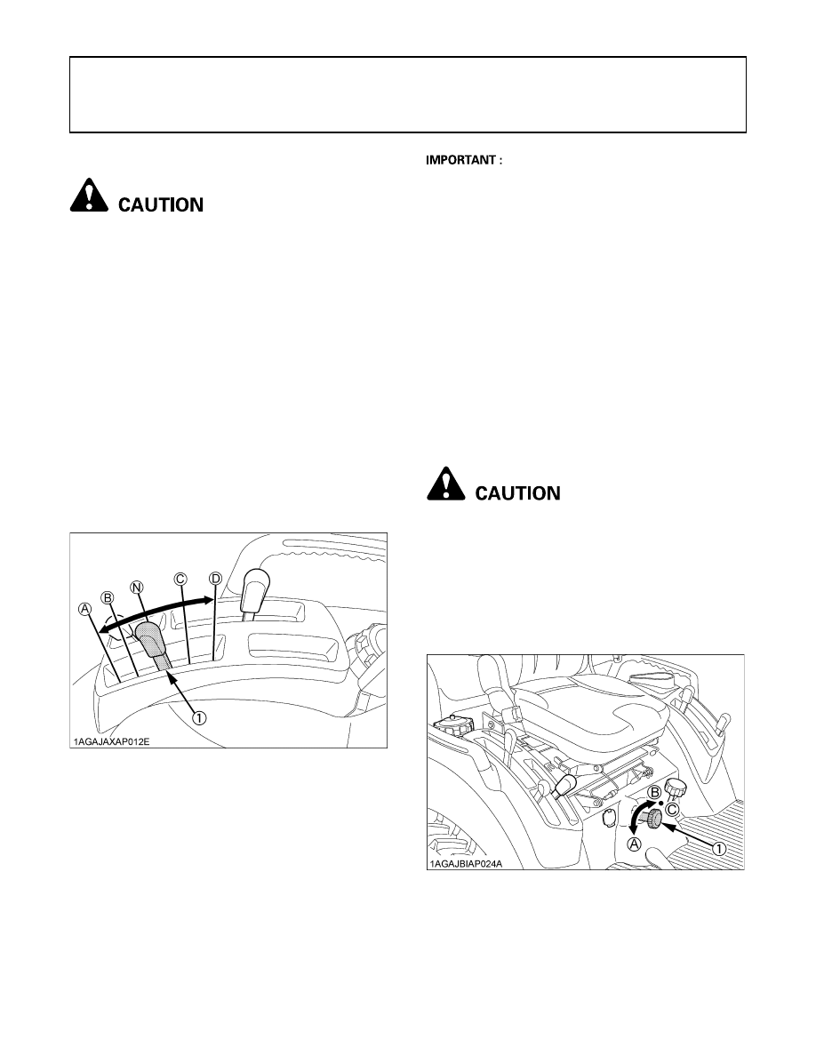
(1) Hydraulic control lever

(A) "DOWN"
(B) "SLOW DOWN"
(N) "NEUTRAL"
(C) "SLOW UP"
(D) "UP"

(1) 3-point hitch lowering speed knob (A) "FAST"

(B) "SLOW"
(C) "LOCK"

HYDRAULIC UNIT

50

AUXILIARY HYDRAULICS

On the tractor hydraulic outlet is provided.

To avoid serious personal injury:
A

Escaping hydraulic fluid under pressure can
have sufficient force to penetrate skin, causing
serious personal injury.
Before disconnecting lines, be sure to relieve
all pressure.
Before applying pressure to system, be sure all
connections are tight and that lines, tubes and
hoses are not damaged.
Fluid escaping from a very small hole can be
almost invisible. Use a piece of cardboard or
wood, rather than hands to search for
suspected leaks.
If injured by escaping fluid, see a doctor at
once. Serious infection or allergic reaction will
develop if proper medical treatment is not
administered immediately.

B

Hydraulic Outlet

It can be used with the BT602 Backhoe.

When mounting the backhoe.
1. Disconnect the coupler.

2. Route the implement inlet, outlet, and power beyond

hose as shown in the illustration.

A

For hydraulic outlet, be sure to use the control valve of
the "Power beyond type" (with relief valve) and third
line return to tank for the operation of hydraulic block.

(1) Coupler

(1) Inlet hose (backhoe)
(2) Outlet hose (backhoe)
(3) Power beyond hose (backhoe)
(4) Outlet hose (tractor)
(5) Return pipe (tractor)
(6) Power beyond pipe (tractor)

(A) To Backhoe (outlet)
          Max. flow
          14 L/min.
(B) From Backhoe (inlet)
(C) Return to tank

51

HYDRAULIC UNIT

INSTALLING MOWER

Do not attach nor operate the mower with the backhoe still
in place.
When installing the mower, remove the backhoe from the
tractor with following procedure.

To avoid serious personal injury:
A

Escaping hydraulic fluid under pressure can
have sufficient force to penetrate skin, causing
serious personal injury.
Before disconnecting lines, be sure to relieve
all pressure.
Before applying pressure to system, be sure all
connections are tight and that lines, tubes and
hoses are not damaged.
Fluid escaping from a very small hole can be
almost invisible. Use a piece of cardboard or
wood, rather than hands to search for
suspected leaks.
If injured by escaping fluid, see a doctor at
once. Serious infection or allergic reaction will
develop if proper medical treatment is not
administered immediately.

C

Disconnecting and connecting the hoses

1. Shut the engine off and set the parking brake.
2. Tilt the operator's seat forward.
3. Remove hydraulic pressure by moving the controls.
4. Disconnect the backhoe inlet hose, outlet hose and

power beyond hose.

5. Place the protective cap on the coupler of the backhoe

inlet hose, the coupler of the outlet hose, and power
beyond hose.

6. Connect the tractor outlet hose to the coupler of power

beyond pipe.

7. Place the protective cap on the nipple of the tractor

return pipe.

A

When getting ready to use the backhoe after finishing
mowing, connect the hoses of the tractor and backhoe
in reverse order.

(1) Inlet hose (backhoe)
(2) Outlet hose (backhoe)
(3) Power beyond hose (backhoe)
(4) Outlet hose (tractor)

(1) Outlet hose (tractor)
(2) Power beyond pipe (tractor)

(A) To be connected

HYDRAULIC UNIT

52

MOWER LIFT LINKAGE SYSTEM

B

Cutting Height Control Dial

When mounting the Mid-mount mower, turn the cutting
height control dial to the desired height.
For further details, refer to the operator's manual of
ROTARY MOWER RCK60B-23BX, RCK54P-23BX and
RCK54-23BX.

When operating the tractor without Mid-mount mower:

1. Move the hydraulic lever rearward to raise the mower

rear links to the highest position.

2. Set the cutting height control dial to "TOP" position.

If this is not done, damage of the mower rear link can
result.

(1) Cutting height control dial
(2) Hydraulic control lever

(1) Mower rear link


Content   ..  18  19  20  21   ..