Challenger Terra Gator 3244 Chassis. Manual - part 93


  Index      Challenger     Challenger Terra Gator 3244 Chassis - service repair manual 2009 year


Search            


Content   ..  91  92  93  94   ..


Challenger Terra Gator 3244 Chassis. Manual - part 93


Removal and Disassembly from 
the Vehicle

WARNING

To prevent serious eye injury, always wear safe eye
protection when you perform vehicle 
maintenance or service.

Park the vehicle on a level surface. Block the
wheels to prevent the vehicle from moving. Support
the vehicle with safety stands. Do not 
work under a vehicle supported only by jacks.
Jacks can slip and fall over. Serious personal
injury can result.

Use a brass or leather mallet for assembly and 
disassembly procedures. Do not hit steel parts with
a steel hammer. Pieces of a part can break off and
cause serious personal injury.

NOTE:

Any pre-cleaning on vehicle to remove

dirt/grease or corrosive material should be per vehicle

manufacturer recommendations. Care should be 

taken to cover the axle breather to limit additional 

contamination during pre-cleaning process.
1. Park the vehicle on a level surface and block the

wheels to prevent the vehicle from moving.

2. Raise the vehicle so that the area you will service is

off of the ground. Support the vehicle with safety

stands. Refer to the vehicle maintenance manual 

for instructions on raising the vehicle.

3. Remove and plug any hydraulic differential lock

actuation line and any connection to the axle with

integral wet brakes by following the OEM vehicle

manufactures instructions to close hydraulic valves

and plug lines and safe draining of fluids as

required. Also disconnect any supplement greasing

lines should the trunnion carrier design require 

servicing per OEM vehicle manufacturers 

recommendation.

NOTE:

Dispose of all collected fluids and grease in an

environmentally friendly approved practice.
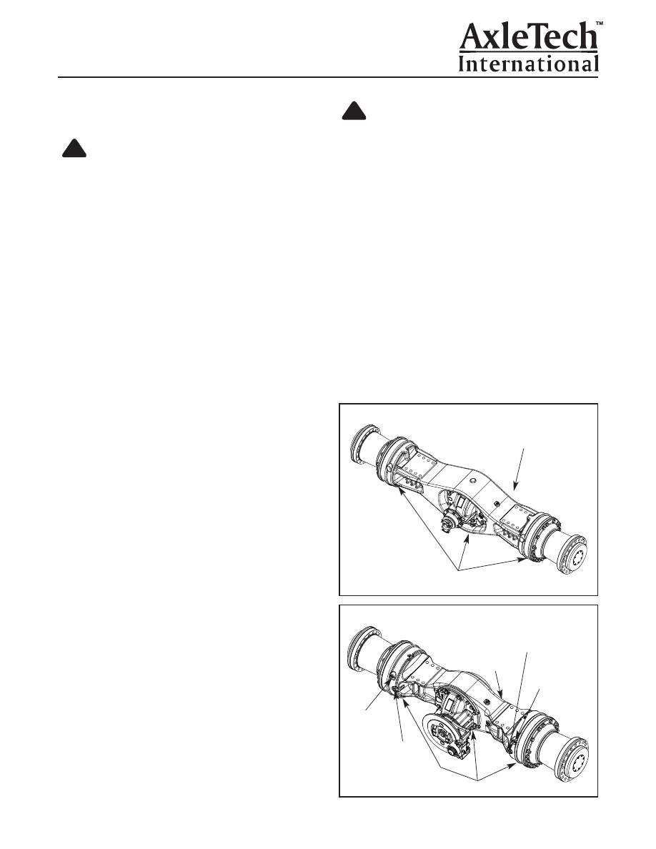
4. Remove the magnetic oil drain plugs from the axle

housing bowl (1.06"-12) and each axle housing

flange to drain the lubricant into a suitable 

container. Note amount of metal on the magnetic drain

plug and clean drain plug. Figure 2.2 and 2.3.

5. Disconnect the vehicle propshaft from the axle input

yoke per vehicle manufacturer recommendations.

Care should be taken so personal injury does 

not occur.

!

WARNING

Take care when using lifting devices. When 
you use a lifting strap, inspect the strap for 
damage before you use it. Do not use a lifting
strap to shock load or drop load a component.
Serious personal injury and damage to 
components can result.

!

Figure 2.1

WET BRAKE
INSPECTION
PORT

WET DISC BRAKE INSPECTION PORT

Trunnion Mount Axle Assembly With Wet Brake

FILL PLUG

MAGNETIC DRAIN PLUG

Figure 2.3

Figure 2.2

FILL PLUG

MAGNETIC DRAIN PLUG

BRAKE
ACTUATION
PORT
FITTING

BRAKE ACTUATION
PORT FITTING

Rigid Mount Axle Assembly Less Wet Brake

Rigid Mount Axle With Park Brake

Section 2
Removal & Disassembly

Page 10

WET DISC
BRAKE
INSPECTION
PORT

FILL PLUG

WET BRAKE
INSPECTION
PORT

MAGNETIC DRAIN PLUG

Page 12

NOTE:

If the trunnion adapter located on the axle

housing bowl side must be removed, use the 

following recommended procedure: Figure 2.5.

1. Remove the (10) M12 capscrews from the adapter

assembly to housing attachment. 

NOTE:

Liquid gasket was applied at original 

production assembly.
2. Safely set the trunnion adapter assembly on the

work bench for later inspection.

3. Remove the trunnion shaft from the adapter.
4. Remove the thrust washer and shims from the

trunnion adapter assembly.

Disassembly of the Carrier Input
Trunnion Assembly

CAUTION

Do not let front trunnion bracket fall off of carrier
during yoke removal.

CAUTION

Care should be taken to avoid dropping the 
internal thrust washer or damaging the inner 
seal lip if the seal supports the bracket weight.
Set the trunnion assembly with seal journal 
facing upwards

.

1. Remove the yoke nut and the yoke assembly.
2. Carefully remove the carrier trunnion bracket assem-

bly by oscillating the bracket assembly while sliding 

it off the carrier input bearing cage. Figure 2.6.

!

!

CAUTION

The seals will be destroyed when removed from
the trunnion housing or carrier’s bearing cage.
New seals will be required during reassembly.
3. Remove the grease seals with a suitable seal

removal tool, if required. 

CAUTION

Care should be taken not to damage the bushing
journal surface or bushing edges during 
disassembly.
4. Remove the bushing from the trunnion bracket

assembly using a suitable removal tool, if required.

Please refer to tool number 5 in Tool Section.

Axle Disassembly Procedure

The trunnion option axle is serviced identically 

internally to the “less trunnion” axle assembly unless

where noted in this manual. The same is true for the

axle with wet brakes and “less wet brakes” feature.

The manual is written to service the standard axle

and each optional feature has been reviewed in 

separate sections as the trunnion and wet brake 

are available in both the rigid mount and trunnion

mount axle designs. The following procedure is 

recommended to disassemble the axle assembly.

Wheel End Disassembly Procedure

If the axle being serviced has the trunnion optional

feature, the trunnion components should be removed

first. Once the trunnion components are removed or

the axle is “less trunnion” feature, continue with the

following disassembly procedure.
NOTE:

There may be some small quantity of oil

remaining within the planetary wheel end reduction

when the planetary assembly is opened. Care should

be taken to capture this small amount of oil for safe

and recommended disposal practices.
1. Remove the M18 capscrews and washers from the

spindle to axle housing joint. Figure 2.7.

!

!

Section 2
Removal & Disassembly

Figure 2.5

TRUNNION
ADAPTER

CAPSCREW

Figure 2.6

THRUST WASHER

BUSHING

TRUNNION
BRACKET

SEAL

SEAL

Page 13

NOTE:

These capscrews had medium strength thread

locker added at original axle assembly.

WARNING

Take care when using lifting devices. When 
you use a lifting strap, inspect the strap for 
damage before you use it. Do not use a lifting
strap to shock load or drop load a component.
Serious personal injury and damage to 
components can result. Figure 2.8.
2. Support the wheel end to be serviced with a 

lifting device.

3. Loosen without removing the M18 lock nuts and

washers at the studs at the spindle to axle housing

joint. Figure 2.8.

CAUTION

Do Not remove the studs as they support the
planetary ring gear and spindle assembly on the
axle housing. Use care to keep planetary ring
gear from falling off spindle flange.
4. Use a brass or leather mallet to hit spindle flange

and loosen wheel end assembly from the axle

housing. Figure 2.9.

!

!

5. Remove O-Ring from inner side of ring gear. For

safety, remove M18 lock nuts while wheel end is

still supported by studs, assemble (2) M18 cap-

screws with washers through spindle flange and

planetary ring gear mounting holes and assemble

(2) nuts with washers onto capscrew threads so

the ring gear cannot fall off the spindle flange.

Figure 2.9.

6. Remove the wheel end assembly from the axle

housing assembly and place safely on a work

bench. Where further wheel end disassembly can

be completed. Figure 2.9.

NOTE:

If the axle to be serviced does not require 

the planetary wheel end assembly to be further 

disassembled, please go to required section for 

specific area of disassembly required. 
NOTE:

To further disassemble the planetary wheel

end assembly and to service all the internal 

wheel end components, the following procedure is

recommended:
1. For further disassembly set with planetary pin 

facing downward with planet pins on a 50mm thick

spacer whose O.D. is smaller than ring gear’s I.D.

Figure 2.10.

Figure 2.9

WHEEL END
ASSEMBLY

SPINDLE
FLANGE

PLANETARY
RING GEAR

LIFTING STRAP

TWO M18 CAPSCREWS AND
NUTS INSTALLED, FOR SAFETY

REMOVE
O-RING

Section 2

Removal & Disassembly

Figure 2.8

WHEEL END ASSEMBLY

Figure 2.7

M18 CAP SCREWS
AND WASHERS

Figure 2.10

LIFTING STRAP

M18 LOCK NUTS

PLANETARY
SPIDER
ASSEMBLY

RING
GEAR

50mm THICK
SPACER

SPINDLE
AND HUB
ASSEMBLY

BOLTS
NUTS AND
WASHERS
FOR SAFETY

Page 14

2. Remove the socket head M8 capscrews from the

cover on the planetary wheel end. Figure 2.11.

NOTE:

These capscrews had a medium strength

thread locker applied at original production assembly.
3. Remove the cover and O-ring from the driver.

Figure 2.12.

4. Remove the snap ring from the planetary spider.

The snap ring removal will now permit the wheel

end spindle and hub assembly to be carefully

removed as a sub assembly from the planetary 

spider assembly. Figure 2.12.

5. Remove the (3) M8 socket head capscrews that

retain the driver to wheel hub. Figure 2.13.

NOTE:

These capscrews had medium strength 

thread locker applied at original assembly.
6. Remove the driver and larger O-ring from the

wheel hub.

7. Remove the (3) M8 socket head capscrews from 

the lockplate that retains the wheel bearing 

adjusting nut. Figure 2.14.

NOTE:

These capscrews had medium strength 

thread locker applied at original assembly.
8. Remove the wheel bearing adjusting nut. Early

design nut was hexagonal. Later design is round

nut shown. A special tool (860901008T) is available

that fits both nuts. (See Special Tool Section for

description).

NOTE

: The bearing cups stay with the wheel hub and

the outer bearing cone will be loose while being 

disassembled from spindle. The inner bearing cone

will be removed with the wheel hub assembly and 

will not stay on the spindle during hub assembly

removal. Half of the TRS toric ring face seal will be

removed as part of  the planetary hub assembly 

when removed. 

Section 2
Removal & Disassembly

Figure 2.14

INNER BEARING
CONE

BEARING CONE

CAPSCREW

WHEEL

BEARING

ADJUSTING

NUT

HUB ASSEMBLY

TRS TORIC RING STYLE

FACE SEAL ASSEMBLY

INNER BEARING

SPACER

SPINDLE

LOCK
PLATE

Figure 2.13

DRIVER

DRIVER REMOVAL

O-RING

M8 CAPSCREW

Figure 2.12

PLANETARY SPIDER ASSEMBLY

SNAP RING

M8 CAPSCREW

COVER

O-RING

Figure 2.11

M8 CAPSCREW

O-RING

COVER


Content   ..  91  92  93  94   ..