Challenger Terra Gator 3244 Chassis. Manual - part 41
16
KENR6054
Disassembly and Assembly Section
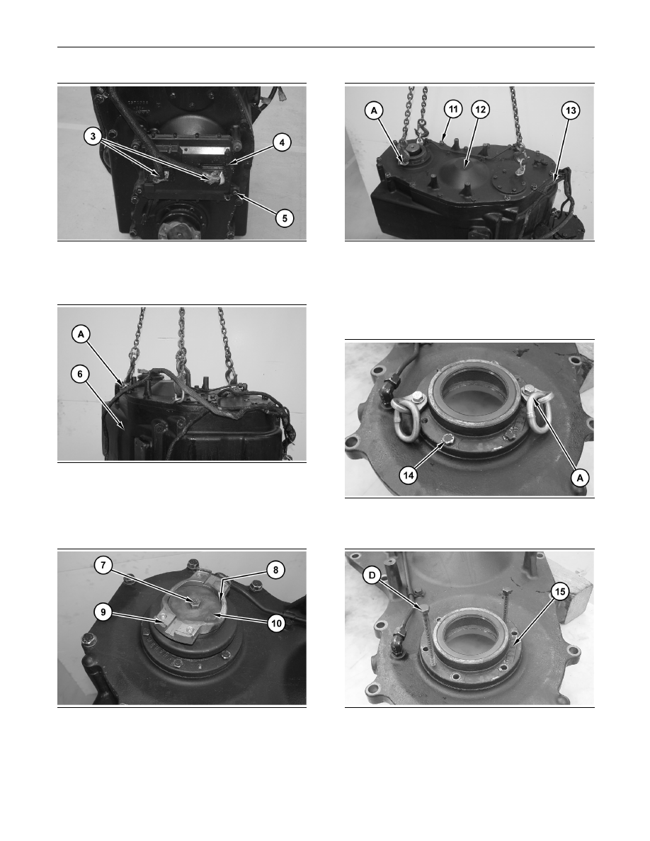
g01269023
Illustration 53
2. Disconnect harness assemblies (3). Remove bolts
(5) and electronic control module (4).
g01269041
Illustration 54
3. Use Tooling (A), Tooling (B), and a suitable lifting
device in order to reposition transmission (6) onto
Tooling (C). The weight of transmission (6) is
approximately 1315 kg (2900 lb).
g01269046
Illustration 55
4. Remove bolt (7) and retainer (10). Remove yoke
(9) and O-ring seal (8).
g01269055
Illustration 56
5. Reposition harness assembly (13). Attach Tooling
(A) and a suitable lifting device to cover assembly
(12). The weight of cover assembly (12) is
approximately 60 kg (130 lb). Remove bolts (11)
and cover assembly (12).
g01269057
Illustration 57
6. Remove bolts (14) and Tooling (A).
g01269063
Illustration 58