Challenger Terra Gator 3244 Chassis. Manual - part 39
8
KENR6054
Disassembly and Assembly Section
g01209450
Illustration 13
6. Install O-ring seal (4).
g01209441
Illustration 14
7. Install cover (3) and bolts (2). Tighten bolts (2) to
a torque of 28 ± 7 N·m (21 ± 5 lb ft).
g01209440
Illustration 15
8. Install O-ring seal (1).
End By:
a. Install the relief valve. Refer to Disassembly and
Assembly, “Relief Valve (Transmission Hydraulic
Control) - Install”.
i02648785
Relief Valve (Transmission
Main) - Install
SMCS Code: 5069-012-T3
Installation Procedure
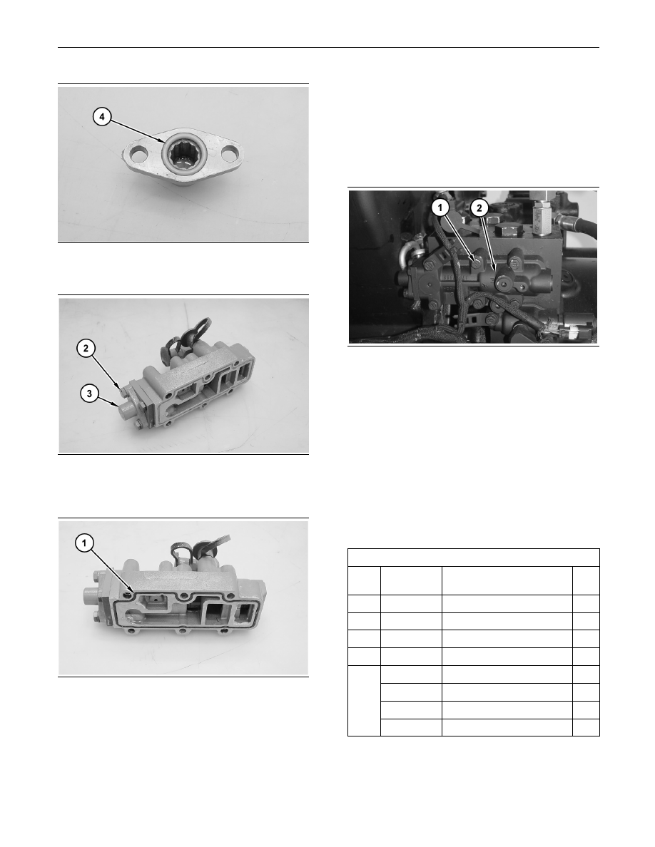
g01329210
Illustration 16
1. Install relief valve (2).
2. Install bolts (1). Tighten bolts (1) to a torque of
30 ± 4 N·m (22 ± 3 lb ft).
i02648891
Pump Drive - Remove
SMCS Code: 3108-011
Removal Procedure
Table 3
Required Tools
Tool
Part
Number
Part Description
Qty
A
138-7575
Link Brackets
4
B
1U-9202
Lever Puller Hoist
1
C
1P-2420
Transmission Repair Stand
1
D
154-6181
Forcing Screws
2
1P-0510
Driver Gp
1
8B-7551
Bearing Puller Gp
1
126-7181
Sliding Plates
4
E
6V-3010
Puller Gp
1