TM 10-8400-203-23&P. Manual - part 19


  Index      Manuals     TM 10-8400-203-23&P. Repair Manual 2010 year


Search            copyright infringement  


Content   ..  17  18  19  20   ..


TM 10-8400-203-23&P. Manual - part 19


TM 

10-8400-203-23&P 

0021 

BASIC TROUSER REPAIR – CONTINUED  

0021-3 

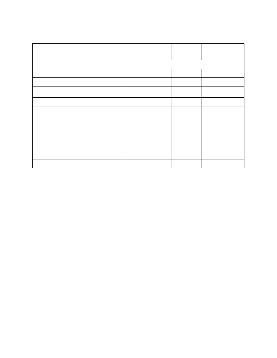
Table 1. BASIC Sewing Requirements. 


COMPONENT 

RECOMMENDED 

SEWING MACHINE 

(CODE SYMBOL) 

STITCHES 

PER INCH 

TYPE 

THREAD 

SIZE 

BALLISTIC TROUSERS 

General  

Medium Duty 

8 to 10 

301 

Bar Tack  

Bar Tack 

28 

301 

Overedge  

Medium Duty 

6 to 8 

502 
503 

Hook and loop fastener tape  

Medium Duty 

9 to 11 

301 

Overedge ballistic insert  

Medium Duty 

6 to 8 

502 
503 
504 
505 

E/F 

Sewing ballistic inserts into the shell 
components  

Medium Duty 

6 to 8 

301 

Sewing inner or outer shell  

Medium Duty 

9 to 11 

301 

Assemble wide and narrow upper leg 
and lower leg strap  

Medium Duty 

9 to 11 

301 

Assemble shoulder pad  

Medium Duty 

9 to 11 

301 

 
Outer Shell Replacement 
 
The outer shell, including the hook and loop fastener tape, may be replaced it is badly tom, worn or 
damaged.  
 
1.  If the protective trousers exhibit holes or tears, seam openings or frayed areas larger than 3 inches, 

or the hook and loop fasteners are inoperative, replace the entire shell section by removing the 
ballistic inserts.  

2.  Cut material for new outer shell to dimensions specified in Table 2.  

3.  Sew as specified in Table 1.  

4.  If the outer shell is to be removed and replaced, it is important that the label containing the size, 

National Stock Number, and cleaning instructions be retained and stitched to the new shell.  

5.  Check the ballistic insert size markings for legibility and remark if necessary.  

6.  If the label is illegible, replace it with a new one. 


TM 

10-8400-203-23&P 

0021 

BASIC TROUSER REPAIR – CONTINUED  

0021-4 

Table 2.  Cloth Measurements for Ballistic Trouser Repair. 


Application 

Dimension (± 1/8 Inch) 

 Length 

Width 

Upper Leg, Shell, Outer  

36 

19 1/2 

Lower Leg, Shell, Outer  

24 1/2 

14 1/4 

Crotch Protector, Shell, Outer  

11 1/2 

7 1/2 

Waistband, Inside  

9 1/2 

2 1/2 

Waistband, Outside  

21 1/2 

9 1/2 

Strap, Wide, Upper Leg, Inside  

9 1/2 

Strap, Wide, Upper Leg, Outside  

9 3/4 

9 1/2 

Strap, Narrow, Upper Leg, Inside  

4 1/2 

5 1/2 

Strap, Narrow, Upper Leg, Outside  

10 1/2 

5 1/2 

Strap, Lower Leg, Inside  

5 1/2 

Strap, Lower Leg, Outside  

91/2 

5 1/2 

Shoulder Pad, Shell  

10 3/4 

 
END OF TASK 
 
Hook and Loop Fastener Tape 
 

CAUTION 


Do not stitch through an insert except where it was stitched during original construction, 
as this may damage the material. 

 
1.  Remove the damaged hook and loop fastener tapes from the strap while avoiding damage to the 

strap. 

2.  Cut fastener tape of the type and dimensions specified in Table 3. 

3.  Machine stitch as specified in Table 1.  


TM 

10-8400-203-23&P 

0021 

BASIC TROUSER REPAIR – CONTINUED  

0021-5 

Table 3.  Hook and Loop Fastener Tape Measurements for Ballistic Trousers. 

Application 

Type Tape 

Dimensions (± 1/8 Inch) 


Length 

Width 

Strap waistband  

Hook  

10 

Strap waistband  

Loop  

Waistband, abdomen  

Loop  

10 

Strap, upper leg, wide  

Hook  

Strap, upper leg, wide  

Loop  

10 

Strap, upper leg, narrow  

Hook  

Strap, upper leg, narrow  

Loop  

Strap, lower leg  

Hook  

Strap, lower leg  

Loop  

Strap, groin protector  

Hook  

1 1/2 


END OF TASK 

Label Replacement 

Each pair of protective trousers must have a combination size and instruction label. If a National Stock 
Number (NSN) and size designation on the label is not legible or will not retain legibility after re-issue, 
remove the old and install a new label, stitching in an appropriate new label as specified in Table 1. If 
label is missing or illegible, perform a dry weight test (adjusting to the nearest whole ounce) and refer to 
Table 4 for size and corresponding NSN determination. Format and content of the label is shown in 
Figure 1. 

Table 4. Dry Weight Test. 

Weight Range (pounds) 

Size 

NSN 

13.00 to 14.25 

Small 

8470-01-472-3421

14.26 to 15.49 

Medium 

8470-01-472-3426 

15.50 to 16.75 

Large 

8470-01-472-3427 


TM 

10-8400-203-23&P 

0021 

BASIC TROUSER REPAIR – CONTINUED  

0021-6 

Figure 1.  Ballistic Trousers Label Data. 

END OF TASK 

PROTECTIVE OVERBOOTS REPAIR 

The only maintenance authorized is lace replacement. Cut lace from nylon material to a minimum length 
of 97 inches. Sear ends and install. 

END OF TASK 

END OF WORK PACKAGE 


 TM 

10-8400-203-23&P 

0022 

0022-1 


FIELD MAINTENANCE 

ADVANCED COMBAT HELMET 

INSPECT, SERVICE, REPAIR 


INITIAL SETUP: 


Tools Materials/Parts 
 

Thread Locking Compound (WP 0047, Item 31) 

Tape, Measuring 

Polyurethane Coating, MIL-DTL-64159, Type I, 
Color 34094 of FED-STD-595  (WP 0047, Item 
32) 

Calipers, Outside (WP 0037, Item 10) 

Polyurethane Coating, MIL-DTL-64159, Type II, 
Color 34094 of FED-STD-595  (WP 0047, Item 
33) 

Screwdriver, Flat Tip (WP 0046, Item 23

Putty  (WP 0047, Item 34) 


Grain, Abrasive, MIL-G-5634, Type 6 (WP 0047, 
Item 35) 

Personnel Required 

Adhesive (for Edging) (WP 0047, Item 36) 

Non-MOS Specific (1) 

Cleaning Compound, Solvent  (WP 0047, Item 
37) 

References 

Isopropyl Alcohol (WP 0047, Item 38) 

WP 0005 

Attachment Tab (WP 0037, Item 11) 

WP 0007 

Strap, Chin Only, Retention FG (WP 0037, Item 
4) 

WP 0037 

Pad, Suspension System, Ach, Foliage Green 
(WP 0037, Item 6) 

WP 0047 

Pad, Helmet, Army Combat, Foliage Green (WP 
0037, Item 7) 


Pad, Helmet, Army Combat, Foliage Green (WP 
0037, Item 8) 


Fastener Tape, Hook (WP 0037, Item 9) 


Screw Mounting (WP 0037, Item 12) 


Mounting Screw (WP 0037, Item 13) 


Post Mounting (WP 0037, Item 14) 


Bracket, Lever (NVD Front Bracket Assembly) 
(WP 0037, Item 16) 


Screw, Machine (8-32 X 3/8 -In Long) (WP 0037, 
Item 17) 


Post, Helmet (NVD Front Bracket) (WP 0037, 
Item 18) 


Strap, Eyewear Retention, Foliage Green (WP 
0037, Item 19


Edging (WP 0037, Item 21


 TM 

10-8400-203-23&P 

0022 

0022-2 

INSPECT 
 
Inspect the helmet for split or cut rubber edging, chipped paint, raised or abraded fibers, cuts, 
delamination, blistering, pitting or slight indentations, loose or missing hardware, cut of abraded retention 
system webbing or damage to the pads or hook disks. 
 
Examine the inside and outside surfaces of the helmet shell for raised or abraded fibers, cuts, pitting or 
slight indentations. If it is determined that the above defects are limited to the outside plies only (on the 
inside and outside of the shell), and the defects do not extend beyond one ply deep, then the helmet shell 
can be repaired. If damaged extends beyond one ply deep, then the helmet shell is not serviceable. 

END OF TASK 

SERVICE 

1.  Remove retention system and pads (See TM 10-8470-204-10).  

2.  Wash the helmets for 10-15 minutes in a 0.5 percent soap solution at a water temperature of 120°F 

(40°C). Rinse them in clear water until soap is removed. Allow them to air dry thoroughly in a 
temperature not exceeding 140°F (60°C). 

3.  Inspect the rubber edging for cuts, slits, and areas of non-adherence. 

a.  If it is determined that the edging is no longer serviceable, then remove the edging by grasping 

edging with pliers and pull edging away from helmet; some scraping may be required. 

b.  Remove any remaining adhesive before installing new edging to helmet. 

c.  The edging, slightly longer than the periphery of the helmet, should be opened up and wound 

around a cylinder so that the inside of the channel is exposed. 

d.  The inside of the edging should be lightly abraded with a wire brush and the adhesive (See 

Section III) applied. 

e.  Adhesive should also be applied to the helmet edge. 

f.  The application of the edging should start at the center of the rear of the helmet and follow the 

periphery of the helmet completely around to the starting at the benchmark at the rear of the 
helmet. 

g.  The edging should be cut so that the ends abut each other. 

4.  Inspect the inside and outside surfaces of the helmet shell for raised or abraded fibers, cuts, pitting or 

slight indentations. If raised or abraded fibers, cuts, pitting or slight indentations are found, repair as 
described in paragraph 28-6 above. 

5.  Inspect the helmet shell for chipped paint. Repair these places without stripping the paint from the 

helmet. Using the coating (see Section III) and the procedure described in paragraph 28-6 above, 
repaint the helmet except that the second coat should cover the entire outside of the helmet 
(including the edging). 

6.  Install a replacement retention system and hook disks. Replace any damaged or missing hardware 

(screw, nut). Install new hook disks and pads. 

END OF TASK 
 

 TM 

10-8400-203-23&P 

0022 

0022-3 

REPAIR 
 
1.  Remove sand and paint around the immediate area of damage, making sure not to cause additional 

raising of fibers. 

2.  Wipe clean with cloth to remove dirt and dust particles. Isopropyl alcohol (see Section III) may be 

used on the cloth. 

3.  Apply one coat of spot putty to cover damaged area sufficiently. Let it cure. 

4.  After spot putty has cured, sand lightly and blend smoothly into shell. 

5.  Apply second coat if required. 

6.  Apply paint as described in section titled Paint Helmet. 

7.  For damage on the inside surface of the helmet shell, follow steps 1 through 6 above. 

 
Paint Helmet 
 
1.  Sand any chipped area slightly before touch up painting, making sure not to cause any raised fibers. 

Clean area with a cloth. Isopropyl alcohol may be used on the cloth.  

2.  Brush or spray on one coat of coating (paint). 

3.  Sprinkle a small amount of silica sand or walnut shell flour on the freshly coated area until the 

quantity of sand or walnut shell is equal to that in the original finish.  

4.  Lightly apply a second coat of coating to cover the unpainted particles and allow the area to dry at 

least eight hours.  

5.  Install retention system as described in section titled Replace Chinstrap Retention System. 

END OF TASK 


Replace Chinstrap Retention System 

1.  Slide elastic bands off loose ends of webbing. 

2.  Unthread the chinstrap retention system webbing from the buckle assembly

3.  Lay the helmet on its crown with the front of the helmet away from you (buckle is located on right side 

of helmet.) 

 TM 

10-8400-203-23&P 

0022 

REPAIR – CONTINUED  

0022-4 

4.  Drape the replacement chinstrap retention system over the helmet with the nape-strap pad facing 

down on the back/rear of the helmet (Figure 1). 


Figure 1. Chinstrap Retention System Replacement. 

5.  Insert and thread the four legs of the chinstrap into their corresponding buckle assemblies (Figure 2.) 

(See Figure 1 for assembled chinstrap retention system orientation.) Take care to ensure that 
webbing is not twisted. 


Figure 2. Hardware Replacement. 

6.  Slide elastic band over loose ends of webbing. 

END OF TASK 


Content   ..  17  18  19  20   ..