Yamaha XV1700P, XV1700PC. Service Manual - part 29
7 - 12
–
+
ELEC
CHECKING THE BULBS AND BULB SOCKETS
EAS00732
CHECKING THE BULBS AND
BULB SOCKETS
Check each bulb and bulb socket for damage
or wear, proper connections, and also for con-
tinuity between the terminals.
Damage/wear
→
Repair or replace the
bulb, bulb socket or both.
Improperly connected
→
Properly connect.
No continuity
→
Repair or replace the bulb,
bulb socket or both.
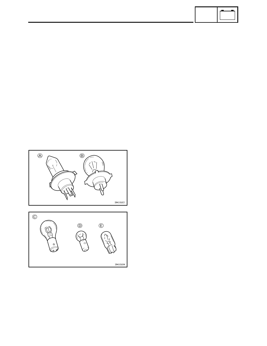
TYPES OF BULBS
The bulbs used on this motorcycle are shown
in the illustration on the left.
• Bulbs
A
and
B
are used for the headlights
and usually use a bulb holder that must be
detached before removing the bulb. The
majority of these types of bulbs can be
removed from their respective socket by
turning them counterclockwise.
• Bulbs
C
is used for turn signal and tail/
brake lights and can be removed from the
socket by pushing and turning the bulb
counterclockwise.
• Bulbs
D
and
E
are used for meter and indi-
cator lights and can be removed from their
respective socket by carefully pulling them
out.
CHECKING THE CONDITION OF THE
BULBS
The following procedure applies to all of the
bulbs.
1. Remove:
• bulb