Yamaha XV1700P, XV1700PC. Service Manual - part 30
7 - 28
–
+
ELEC
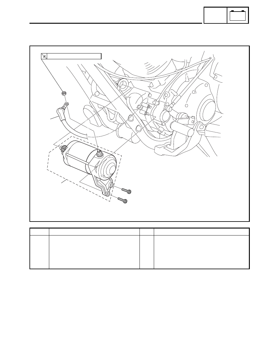
STARTER MOTOR
EAS00767
STARTER MOTOR
2
1
T
R
.
.
5 Nm (0.5 m
•
kg, 3.6 ft
•
Ib)
Order
Job/Part
Q’ty
Remarks
Removing the starter motor
Remove the parts in the order listed.
1
Starter motor lead
1
2
Starter motor assembly
1
For installation, reverse the removal
procedure.