Yamaha XV1700P, XV1700PC. Service Manual - part 27
6 - 25
FI
FUEL INJECTION SYSTEM
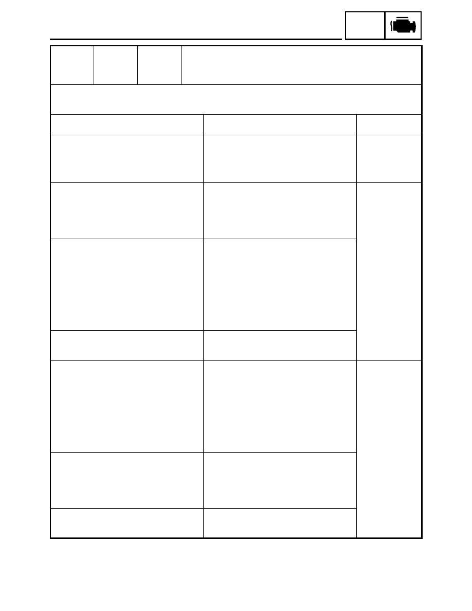
Code No.
26
Symptom
1 Intake air pressure sensor 2 - pipe system malfunction (clogged or
detached hose).
2 Intake air pressure sensor 2 - open or short circuit detected.
3 Stuck throttle position sensor detected.
Used diagnostic code
No. 04 (intake air pressure sensor 2)
No. 01 (throttle position sensor)
No. 02 (atmospheric pressure sensor)
Inspection operation item and probable cause Operation item and countermeasure
Reinstatement
method
1.Common to 1, 2, and 3:
Connected state of connector
Inspect the coupler for any pins that may
have pulled out.
Check the locking condition of the coupler.
If there is a malfunction, repair it and connect it
securely.
Intake air pressure sensor coupler
Main wiring harness ECU coupler
Reinstated by
starting the engine
and operating it at
idle.
2-1.Intake air pressure sensor hose detached,
clogged, kinked, or pinched.
Intake air pressure sensor malfunction at
intermediate electrical potential.
Atmospheric pressure sensor malfunction
at intermediate electrical potential.
Repair or replace the sensor hose.
Inspect and repair the connection.
Replace it if there is a malfunction.
See page 6-25
Reinstated by
starting the engine
and operating it at
idle.
2-2.Open or short circuit in wiring harness or
sub lead.
Repair or replace if there is an open or short
circuit.
Main wiring harness
Black/Blue - Black/Blue
Pink/White - Pink/White
Blue - Blue
Sub lead
Black/Blue - Black/Blue
Pink/White - Pink/White
Blue - Blue
2-3.Defective intake air pressure sensor.
Replace if defective.
Refer to “FUEL INJECTION SYSTEM” in
chapter 7.
3-1.Open or short circuit in wiring harness or
sub lead.
Repair or replace if there is an open or short
circuit.
Main wiring harness
Black/Blue - Black/Blue
Yellow - Yellow
Blue - Blue
Sub lead
Black/Blue - Black/Blue
Yellow - Yellow
Blue - Blue
Reinstated by
starting the engine,
operating it at idle,
and then by racing
it.
3-2.Throttle position sensor lead wire open cir-
cuit output voltage check
(B/L - Y)
Black/Blue - Yellow
Open circuit item:
Output voltage
Ground wire open circuit:
5 V
Output wire open circuit:
0 V
Power supply wire open circuit: 0 V
Check for open circuit and replace the throttle
position sensor.
3-3.Defective throttle position sensor.
Replace if defective.
Refer to “FUEL INJECTION SYSTEM” in
chapter 7.