Yamaha XV1700P, XV1700PC. Service Manual - part 26


  Index      Manuals     Yamaha XV1700P, XV1700PC. Service Manual


Search            copyright infringement  


Content      ..     24      25      26      27     ..


Yamaha XV1700P, XV1700PC. Service Manual - part 26


6 - 9

FI

FUEL INJECTION SYSTEM

TROUBLESHOOTING
Diagnosis mode troubleshooting 1 (self-diagnostic malfunction detected)

By entering a diagnostic code in the ECU through the use of the “SELECT” and “RESET” buttons on
the tachometer, the sensor output values can be displayed and the actuators can be operated in
accordance with the code that has been entered.
The technician determines whether or not the operation is normal by verifying the values displayed
on the tachometer or the operating conditions of the actuators. These modes can be used to detect
and check the problems that are otherwise difficult to detect in the diagnosis mode.

Basic operation procedure

Operation preparation

• Verify the self-diagnostic fault code number that is displayed on the meter.
• Based on the self-diagnostic fault code number, select the applicable sensor or actuator from the

diagnostic code table.

• If a diagnostic code is available, proceed with the operation procedure given below in order to

verify the operating conditions of the applicable sensor or actuator.

Operation procedure (make sure to turn “OFF” the main switch upon completing the operation prep-
aration)

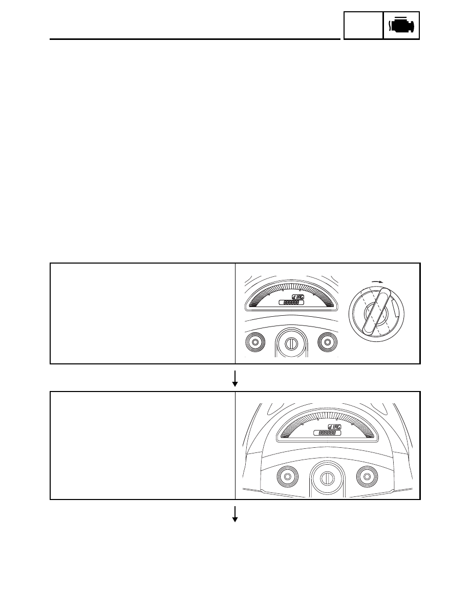
Setting the ECU in the diagnosis mode

1. While keeping the “SELECT” and “RESET”

buttons pressed simultaneously, turn “ON”
the main switch 

1

 (keep them pressed for

8 seconds or more).

* Letters “dIAG” appear on the clock LCD.

Selecting the diagnosis mode

After  “dIAG” appears as a result of pressing
the  “SELECT” button, simultaneously press
the “SELECT” and “RESET” buttons for 2 sec-
onds or more to execute the selection.

OFF

ON

TRIP

km

mile

TRIP

km

mile

0D0

T

1

TRIP

km

mile

0D0

SELECT

RESET

6 - 10

FI

FUEL INJECTION SYSTEM

Verifying the operation of various sensors and
actuators

1. Disconnect the wiring harness coupler from

the fuel pump.

2. Turn the engine stop switch “OFF”.

· Turn the engine stop switch “ON” if diag-

nostic code numbers 03 and 09 are
shown.

3. Select the diagnostic code number that

applies to the item that was verified with the
self-diagnostic fault code number, and
enter it on the meter by operating the
“SELECT” or “RESET” button.

* “RESET” button

Decrement (press 1 second or longer 

 auto)

“SELECT” button
Increment (press 1 second or longer 

 auto)

* Diagnostic code number appears on clock

LCD (01 ~ 70)

4. Verifying the operation of the displayed

diagnostic code
· Verifying various sensors

The data representing the operating con-
ditions of the sensors appears on the trip
LCD (throttle position sensor angle, cool-
ant temperature, atmospheric pressure,
etc.)

· Verifying the operation of actuators

Start the operation by turning the stop
switch “ON” (injectors, relay, ignition coil,
AIS, etc.)

* If the stop switch is “ON”, turn it “OFF”;

then, turn it back “ON”.

5. Check the results by referring to the sensor

operation data verification table or the actu-
ator operation verification table.

Perform individual repairs on the areas where
malfunctions have been identified.

TRIP

km

mile

0D0

SELECT

RESET

SELECT

(01     70)

TRIP

km

mile

0D0

SELECT

RESET

RESET

(01     70)

6 - 11

FI

FUEL INJECTION SYSTEM

Erase the codes appearing on the meter upon
the completion of the operation (reinstating the
ECU).

* Verify the reinstatement procedures

detailed in the troubleshooting details in
order to carry out the reinstatement opera-
tion that is applicable to the malfunctioning
item.
Refer to “troubleshooting details”.

Erase the fault code from memory.

* Perform the operation for diagnostic code

62.

6 - 12

FI

FUEL INJECTION SYSTEM

Self-diagnostic fault codes, symptoms, and probable causes

Diagnostic code indication

Code No.

Symptom

Probable cause of malfunction

Diagnostic code

11

No normal signals are received from 
the cylinder identification sensor.

• Open or short circuit in wiring sub lead.
• Open or short circuit in wiring harness.
• Defective cylinder identification sensor.
• Malfunction in ECU.
• Improperly installed sensor.

12

No normal signals are received from 
the crankshaft position sensor.

• Open or short circuit in wiring harness.
• Defective crankshaft position sensor.
• Malfunction in pickup rotor.
• Malfunction in ECU.
• Improperly installed sensor.

13

Intake air pressure sensor 1 - open or 
short circuit detected.

• Open or short circuit in wiring sub lead.
• Open or short circuit in wiring harness.
• Defective intake air pressure sensor.
• Malfunction in ECU.

03

14

Faulty intake air pressure sensor pipe 
system 1; a hose is detached, caus-
ing constant application of the atmo-
spheric pressure to the sensor; or, the 
hose is clogged.

• Intake air pressure sensor hose is detached, clogged, 

kinked, or pinched.

• Malfunction of the intake air pressure sensor in the interme-

diate electrical potential.

• Malfunction of the atmospheric pressure sensor in the inter-

mediate electrical potential.

• Malfunction in ECU.

03
02

Or, intake air pressure sensor - open 
or short circuit detected.

• Open or short circuit in wiring sub lead.
• Open or short circuit in wiring harness.
• Defective intake air pressure sensor.
• Malfunction in ECU.

03

Or, a stuck throttle position sensor is 
detected.

• Open or short circuit in wiring sub lead.
• Open or short circuit in wiring harness.
• Defective sensor (stuck throttle position sensor).

01

15

Throttle position sensor - open or 
short circuit detected.

• Open or short circuit in wiring sub lead.
• Open or short circuit in wiring harness.
• Defective throttle position sensor.
• Malfunction in ECU.
• Improperly installed throttle position sensor.

01

16

A stuck throttle position sensor is 
detected.
Or,
Faulty intake air pressure sensor pipe 
system; a hose is detached, causing 
constant application of the atmo-
spheric pressure to the sensor; or, the 
hose is clogged.

• Open or short circuit in wiring sub lead.
• Open or short circuit in wiring harness.
• Defective sensor (stuck throttle position sensor).
• Intake air pressure sensor hose is detached, clogged, 

kinked, or pinched.

• Malfunction of the intake air pressure sensor in the interme-

diate electrical potential.

• Malfunction of the atmospheric pressure sensor in the inter-

mediate electrical potential.

• Malfunction in ECU.

01
03
02

19

Open circuit in the input line from the 
sidestand switch to the ECU is 
detected when the start switch is 
pressed.

• Open or short circuit in wiring harness.
• Malfunction in ECU.

20

20

When the main switch is turned to 
ON, the atmospheric sensor voltage 
and intake air pressure sensor volt-
age differ greatly.

• Atmospheric pressure sensor hose is clogged.
• Intake air pressure sensor hose is clogged, kinked, or 

pinched.

• Malfunction of the atmospheric pressure sensor in the inter-

mediate electrical potential.

• Malfunction of the intake air pressure sensor in the interme-

diate electrical potential.

• Malfunction in ECU.

03
02

22

Intake temperature sensor - open or 
short circuit detected.

• Open or short circuit in wiring harness.
• Defective intake temperature sensor.
• Malfunction in ECU.
• Improperly installed sensor.

05

6 - 13

FI

FUEL INJECTION SYSTEM

23

Atmospheric pressure sensor - open 
or short circuit detected.

• Open or short circuit in wiring harness.
• Defective atmospheric pressure sensor.
• Improperly installed sensor.
• Malfunction in ECU.

02

25

Intake air pressure sensor 2 - open or 
short circuit detected.

• Open or short circuit in wiring sub lead.
• Open or short circuit in wiring harness.
• Defective intake air pressure sensor.
• Malfunction in ECU.

02

26

Faulty intake air pressure sensor pipe 
system 2; a hose is detached, caus-
ing constant application of the atmo-
spheric pressure to the sensor; or, the 
hose is clogged.

• Intake air pressure sensor hose is detached, clogged, 

kinked, or pinched.

• Malfunction of the intake air pressure sensor in the interme-

diate electrical potential.

• Malfunction of the atmospheric pressure sensor in the inter-

mediate electrical potential.

• Malfunction in ECU.

03
02

Or, intake air pressure sensor - open 
or short circuit detected.

• Open or short circuit in wiring sub lead.
• Open or short circuit in wiring harness.
• Defective intake air pressure sensor.
• Malfunction in ECU.

03

Or, a stuck throttle position sensor is 
detected.

• Open or short circuit in wiring sub lead.
• Open or short circuit in wiring harness.
• Defective sensor (stuck throttle position sensor).

01

27

Oil temperature sensor - open or 
short circuit detected.

• Open or short circuit in wiring harness.
• Defective oil temperature sensor.
• Malfunction in ECU.
• Improperly installed sensor.

10

28

Engine temperature sensor - open or 
short circuit detected.

• Open or short circuit in wiring harness.
• Defective engine temperature sensor.
• Malfunction in ECU.
• Improperly installed sensor.

11

29

Decompression solenoid (thermistor) 
- open or short circuit detected.

• Open or short circuit in wiring harness.
• Defective decompression solenoid (thermistor).
• Malfunction in ECU.
• Improperly installed sensor.

55

30

The motorcycle has overturned.

• Overturned.
• Malfunction in ECU.

08

37

A faulty linear control valve or motor is 
detected. 

• Open or short circuit in wiring harness.
• Defective linear control valve.
• Malfunction in ECU.
• Improperly installed linear control valve.

10
54

38

Decompression solenoid - open or 
short circuit detected.

• Open or short circuit in wiring harness.
• Defective decompression solenoid.
• Malfunction in ECU.
• Improperly installed sensor.

55

41

Lean angle cut-off switch - open or 
short circuit detected.

• Open or short circuit in wiring harness.
• Defective lean angle cut-off switch.
• Malfunction in ECU.
• Improperly installed sensor.

08

42

No normal signals are received from 
the speed sensor; or, an open or 
short circuit is detected in the neutral 
switch.

• Open or short circuit in wiring harness.
• Defective speed sensor.
• Malfunction in vehicle speed sensor detected unit.
• Defective neutral switch.
• Malfunction in the engine side of the neutral switch.
• Malfunction in ECU.
• Improperly installed sensor.

07
21

43

The ECU is unable to monitor the bat-
tery voltage (an open circuit in the 
monitor line to the ECU).

• Open circuit in wiring harness.
• Malfunction in ECU.

50

Faulty ECU memory. When this mal-
function is detected, the code number 
might not appear on the meter.

• Malfunction in ECU. (The program and data are not properly 

written on or read from the internal memory.)

Code No.

Symptom

Probable cause of malfunction

Diagnostic code

6 - 14

FI

FUEL INJECTION SYSTEM

Sensor operation data display verification table

NOTE:

• Check the intake temperature, engine temperature, and oil temperature as close as possible to

the area in which the respective sensor is mounted.

• If it is not possible to check it with an atmospheric pressure gauge, judge it by using 760 mmHg as

the standard.

• If it is not possible to check the intake temperature, use the ambient temperature as reference

(use the compared values for reference).

Diag code

Item

Description of action

Data displayed on meter 

(reference value)

01

Throttle angle

Displays the throttle angle.
• Check with throttle fully closed.
• Check with throttle fully open.

0 ~ 125 degrees
• Fully closed position (15 ~ 20)
• Fully open position (95 ~ 100)

02

Atmospheric pres-
sure

Displays the atmospheric pressure.
* Use an atmospheric pressure gauge to check the atmo-

spheric pressure.

Compare it to the value dis-
played on the meter.

03

Pressure difference 1

Displays the pressure difference 1 (atmospheric pressure - 
intake air pressure 1).
Engine stop switch is on.
* Generate the pressure difference by cranking the engine 

with the starter, without actually starting the engine.

10 ~ 200 mmHg

04

Pressure difference 2

Displays the pressure difference 2 (atmospheric pressure - 
intake air pressure 2)
* Same as above.

Same as above

05

Intake temperature

Displays the intake air temperature.
* Check the temperature in the air cleaner case.

Compare it to the value dis-
played on the meter.

07

Vehicle speed pulse

Displays the accumulation of the vehicle pulses that are gen-
erated when the tire is spun.

(0 ~ 999; resets to 0 after 999)
OK if the numbers appear on 
the meter.

08

Lean angle cut-off 
switch

Displays the lean angle cut-off switch values.

Upright: 0.4 ~ 1.4 V
Overturned: 3.8 ~ 4.2 V

09

Fuel system voltage 
(monitor voltage)

Displays the fuel system voltage (battery voltage).
Engine stop switch is on.

0 ~ 18.7 V
Normally, approximately 12.0 V

10

Engine oil tempera-
ture

Displays the temperature of the engine oil.

–30 ~ 200 °C (–22 ~ 392 °F)
Cold engine: ambient tempera-
ture or higher
Warm engine: 80 °C or higher

11

Engine temperature

Displays the temperature of the engine.

–30 ~ 200 °C (–22 ~ 392 °F)
Cold engine: ambient tempera-
ture or higher
Warm engine: 100 °C (212 °F) 
or higher

20

Sidestand switch

Displays that the switch is ON or OFF. (When the gear is in a 
position other than neutral.)

Stand retracted: ON
Stand extended: OFF

21

Neutral switch

Displays that the switch is ON or OFF.

Neutral: ON
In gear: OFF

60

E2PROM fault code 
display

• Displays the faulty cylinder that has been detected by a self-

diagnostic fault code.

• If multiple malfunctions have been detected, the same data 

is transmitted 128 times, then different data is transmitted 
repeatedly.

(01 ~ 02) Displays the cylinder 
number.
(00) Displays when there is no 
malfunction.

61

Malfunction history 
code display

• Displays the codes of the history of the self-diagnosis mal-

functions (i.e., a code of a malfunction that occurred once 
and which has been corrected).

• If multiple malfunctions have been detected, the same data 

is transmitted 128 times, then different data is transmitted 
repeatedly.

11 ~ 55
(00) Displays when there is no 
malfunction.

6 - 15

FI

FUEL INJECTION SYSTEM

62

Malfunction history 
code erasure

• Displays the total number of codes that are being detected 

through self diagnosis and the fault codes in the past his-
tory.

• Erases only the history codes when the engine stop switch 

is turned from OFF to ON. If the engine stop switch is ON, 
turn it OFF once, and then turn it back ON.

00 ~ 21
(00) Displays when there is no 
malfunction.

70

Control number

• Displays the program control number.

00 ~ 255

Diag code

Item

Description of action

Data displayed on meter 

(reference value)

6 - 16

FI

FUEL INJECTION SYSTEM

Actuator operation verification table

Diag code

Item

Description of action

Data displayed on meter 

(reference value)

30

Ignition coil #1

After 1 second has elapsed from the time the engine stop 
switch has been turned from OFF to ON, it actuates ignition 
coils #1 for five times every second and illuminates the engine 
trouble warning light.
* Connect an ignition checker.
* If the engine stop switch is ON, turn it OFF once, and then 

turn it back ON.

Check that spark is generated, 
5 times with the engine stop 
switch ON.

31

Ignition coil #2

Take the same actions as No. 30 above on ignition coils #2.
Same as above.
* If the engine stop switch is ON, turn it OFF once, and then 

turn it back ON.

Same as above

36

Injector #1

After 1 second has elapsed from the time the engine stop 
switch has been turned from OFF to ON, it actuates the injec-
tor five times every second and illuminates the engine trouble 
warning light.
* If the engine stop switch is ON, turn it OFF once, and then 

turn it back ON.

Check the operating sound of 
the injector five times with 
engine stop switch ON.

37

Injector #2

Take the same actions as No. 36 above on injector #2.
* If the engine stop switch is ON, turn it OFF once, and then 

turn it back ON.

Same as above

50

Fuel injection system 
relay

After 1 second has elapsed from the time the engine stop 
switch has been turned from OFF to ON, it actuates the fuel 
injection system relay five times every second and illuminates 
the engine trouble warning light (the light is OFF when the 
relay is ON, and the light is ON when the relay is OFF).
* If the engine stop switch is ON, turn it OFF once, and then 

turn it back ON.

Check the fuel injection system 
relay operating sound.
Same as above

52

Headlight relay 

After 1 second has elapsed from the time the engine stop 
switch has been turned from OFF to ON, it actuates the head-
light relay five times every 5 seconds and illuminates the 
engine trouble warning light. (ON 2 seconds, OFF 3 seconds)
* If the engine stop switch is ON, turn it OFF once, and then 

turn it back ON.

Check the relay operating 
sound.
Same as above

54

Linear control valve

After 1 second has elapsed from the time the engine stop 
switch has been turned from OFF to ON, it actuates the linear 
control valve four times every 5 seconds and illuminates the 
engine trouble warning light (fully closed 2 seconds, fully open 
2 seconds).

Check the linear control valve 
operating sound, 3 times with 
the engine stop switch ON.

55

Decompression sole-
noid

After 1 second has elapsed from the time the engine stop 
switch has been turned from OFF to ON, it actuates the 
decompression solenoid five times every 5 seconds and illu-
minates the engine trouble warning light (ON 2 seconds, OFF 
3 seconds).
NOTE: Be sure to turn the start switch to ON, otherwise the 
above mentioned operation will not be possible.

Check the decompression sole-
noid operating sound, 5 times 
with the engine stop switch ON.

6 - 17

FI

FUEL INJECTION SYSTEM

Troubleshooting

The condition of the engine is poor or the engine trouble warning light comes on.
* The engine trouble warning light may not come on even if the condition of the engine is poor.

The engine trouble warning light comes on.

Checking the self-diagnostic fault code
Check the self-diagnostic fault code displayed on the
tachometer.

Specifying a faulty system
Refer to “Diagnostic code indication” to specify the faulty sys-
tem.

Troubleshooting the cause
Refer to “Diagnostic code indication” to troubleshoot the
cause.

Diagnostic code No.

Yes

Resetting the ECU
Refer to “Reinstatement method” in “Troubleshooting details”
to reset the ECU.

Checking the tachometer display
Turn the main switch to OFF, then to ON again to check if a
self-diagnostic fault code is displayed.

Repairs are complete.

Erasing the malfunction history
Even if the main switch is turned to OFF, the malfunction history is recorded. Perform the action described for diagnostic code 62 in
“Sensor operation data display verification table” to delete the malfunction history.

The engine trouble warning light does not come on.

Checking the sensor and actuators
Check the action of the following sensor and actuators
according to the “Description of action” column. (Refer to
“Sensor operation data display verification table” and “Actua-
tor operation verification table”.)
01: Throttle position sensor (throttle angle)
30: Ignition coil #1
36: Injector #1
37: Injector #2

Faulty engine

Refer to chapter 5 to
check and repair the
engine.

Check the condition of the engine.

Irregular sensor or actua-
tors

Check and repair the
applicable sensor and
actuators.

Diagnostic code No.

No

While checking the sensor
and actuators in the “Diag-
nostic monitoring mode”
(refer to “Sensor operation
data display verification
table” and “Actuator opera-
tion verification table”), fol-
low the procedures in
“Troubleshooting details” to
check and repair the mal-
function.

Follow the procedures in
“Troubleshooting details” to
check and repair the mal-
function.

Checking and servicing the faulty estimations

No codeis displayed

OK

Not OK

Not OK

OK

6 - 18

FI

FUEL INJECTION SYSTEM

Troubleshooting details

Troubleshooting the self-diagnostic fault code

Code No.

11

Symptom

No normal signals are received from the cylinder identification sensor.

Used diagnostic code No.

1.Inspection operation item

Operation item and countermeasure

Reinstatement 
method

2.Defective cylinder identification sensor.

Replace if defective.
Refer to “FUEL INJECTION SYSTEM” in 
chapter 7.

Reinstated by 
starting the engine 
and operating it at 
idle.

3.Open or short circuit in wiring harness or 

sub lead.

Repair or replace if there is an open or short 
circuit.
Between main wiring harness and sub lead

Blue - Blue
White/Black - White
Black/Blue - Black/Blue

4.Connected state of connector

Inspect the coupler for any pins that may 
have pulled out.
Check the locking condition of the coupler.

If there is a malfunction, repair it and connect it 
securely.

Cylinder identification sensor coupler
Main wiring harness ECU coupler
Sub-wire harness coupler

5.Installed state of sensor

Check the installed area for looseness or 
pinching.

Code No.

12

Symptom

No normal signals are received from the crankshaft position sensor.

Used diagnostic code No.

Inspection operation item and probable cause Operation item and countermeasure

Reinstatement 
method

1.Installed state of sensor

Check the installed area for looseness or 
pinching.

Reinstated by 
cranking the 
engine.

2.Open or short circuit in wiring harness or 

sub lead.

Repair or replace if there is an open or short 
circuit between the main wiring harnesses.

Gray - Gray
Black/Blue - Black/Blue

3.Connected state of connector

Inspect the coupler for any pins that may 
have pulled out.
Check the locking condition of the coupler.

If there is a malfunction, repair it and connect it 
securely.

Crankshaft position sensor coupler
Main wiring harness ECU coupler

4.Defective crankshaft position sensor.

Replace if defective.
Refer to “FUEL INJECTION SYSTEM” in 
chapter 7.

6 - 19

FI

FUEL INJECTION SYSTEM

Code No.

13

Symptom

Intake air pressure sensor 1 - open or short circuit detected.

Used diagnostic code No. 03 (intake air pressure sensor 1)

Inspection operation item and probable cause Operation item and countermeasure

Reinstatement 
method

1.Open or short circuit in wiring harness or 

sub lead.

Repair or replace if there is an open or short 
circuit.
Main wiring harness

Black/Blue - Black/Blue
Pink/White - Pink/White
Blue - Blue

Sub lead

Black/Blue - Black/Blue
Pink/White - Pink/White
Blue - Blue

Reinstated by turn-
ing the main switch 
ON.

2.Connected state of connector

Inspect the coupler for any pins that may 
have pulled out.
Check the locking condition of the coupler.

If there is a malfunction, repair it and connect it 
securely.

Intake air pressure sensor coupler
Main wiring harness ECU coupler
Sub-wire harness coupler

3.Defective intake air pressure sensor

Replace if defective.
Refer to “FUEL INJECTION SYSTEM” in 
chapter 7.

6 - 20

FI

FUEL INJECTION SYSTEM

Code No.

14

Symptom

1 Intake air pressure sensor 1 - pipe system malfunction (clogged or 

detached hose).

2 Intake air pressure sensor 1 - open or short circuit detected.
3 Stuck throttle position sensor detected.

Used diagnostic code 

No. 03 (intake air pressure sensor 1) 
No. 01 (throttle position sensor)
No. 02 (atmospheric pressure sensor)

Inspection operation item and probable cause Operation item and countermeasure

Reinstatement 
method

1.Common to 1, 2, and 3:

Connected state of connector
Inspect the coupler for any pins that may 
have pulled out.
Check the locking condition of the coupler.

If there is a malfunction, repair it and connect it 
securely.

Intake air pressure sensor coupler
Main wiring harness ECU coupler

Reinstated by 
starting the engine 
and operating it at 
idle.

2-1.Intake air pressure sensor hose detached, 

clogged, kinked, or pinched.
Intake air pressure sensor malfunction at 
intermediate electrical potential.
Atmospheric pressure sensor malfunction 
at intermediate electrical potential.

Repair or replace the sensor hose.
Inspect and repair the connection. 
Replace it if there is a malfunction.

See page 6-25.

Reinstated by 
starting the engine 
and operating it at 
idle.

2-2.Open or short circuit in wiring harness or 

sub lead.

Repair or replace if there is an open or short 
circuit.
Main wiring harness

Black/Blue - Black/Blue
Pink/White - Pink/White
Blue - Blue

Sub lead

Black/Blue - Black/Blue
Pink/White - Pink/White
Blue - Blue

2-3.Defective intake air pressure sensor.

Replace if defective.
Refer to “FUEL INJECTION SYSTEM” in 
chapter 7.

3-1.Open or short circuit in wiring harness or 

sub lead.

Repair or replace if there is an open or short 
circuit.
Main wiring harness

Black/Blue - Black/Blue
Yellow - Yellow
Blue - Blue

Sub lead

Black/Blue - Black/Blue
Yellow - Yellow
Blue - Blue

Reinstated by 
starting the engine, 
operating it at idle, 
and then by racing 
it.

3-2.Throttle position sensor lead wire open cir-

cuit output voltage check
(B/L - Y)
Black/Blue - Yellow

Open circuit item:

Output voltage

Ground wire open circuit:

5 V

Output wire open circuit:

0 V

Power supply wire open circuit: 0 V
Check for open circuit and replace the throttle 
position sensor.

3-3.Defective throttle position sensor.

Replace if defective.
Refer to “FUEL INJECTION SYSTEM” in 
chapter 7.

6 - 21

FI

FUEL INJECTION SYSTEM

Code No.

15

Symptom

Throttle position sensor - open or short circuit detected.

Used diagnostic code No. 01 (throttle position sensor)

Inspection operation item and probable cause Operation item and countermeasure

Reinstatement 
method

1.Installed state of throttle position sensor.

Check the installed area for looseness or 
pinching. 
Check that it is installed in the specified posi-
tion.
Refer to “FUEL INJECTION SYSTEM” in 
chapter 7.

Reinstated by turn-
ing the main switch 
ON.

2.Connected state of connector

Inspect the coupler for any pins that may 
have pulled out.
Check the locking condition of the coupler.

If there is a malfunction, repair it and connect it 
securely.

Throttle position sensor coupler
Main wiring harness ECU coupler

3.Open or short circuit in wiring harness or 

sub lead.

Repair or replace if there is an open or short 
circuit.
Main wiring harness

Black/Blue - Black/Blue
Yellow - Yellow
Blue - Blue

Sub lead

Black/Blue - Black/Blue
Yellow - Yellow
Blue - Blue

4.Throttle position sensor lead wire open cir-

cuit output voltage check
(B/L - Y)
Black/Blue - Yellow

Open circuit item:

Output voltage

Ground wire open circuit:

5 V

Output wire open circuit:

0 V

Power supply wire open circuit: 0 V
Check for open circuit and replace the throttle 
position sensor.

5.Defective throttle position sensor.

Replace if defective.
Refer to “FUEL INJECTION SYSTEM” in 
chapter 7.

6 - 22

FI

FUEL INJECTION SYSTEM

Code No.

16

Symptom

1 Stuck throttle position sensor detected.
2 Intake air pressure sensor - pipe system malfunction (clogged or 

detached hose).

Used diagnostic code 

No. 01 (throttle position sensor)
No. 03 (intake air pressure sensor 1)
No. 04 (intake air pressure sensor 2)
No. 02 (atmospheric pressure sensor)

Inspection operation item and probable cause Operation item and countermeasure

Reinstatement 
method

1.Common to 1 and 2:

Connected state of connector
Inspect the coupler for any pins that may 
have pulled out.
Check the locking condition of the coupler.

If there is a malfunction, repair it and connect it 
securely.

Throttle position sensor coupler
Main wiring harness ECU coupler
Sub-wire harness coupler

Reinstated by 
starting the engine, 
operating it at idle, 
and then racing it.

2.Installed state of throttle position sensor.

Check the installed area for looseness or 
pinching. 
Check that it is installed in the specified 
position. 
Refer to “FUEL INJECTION SYSTEM” in 
chapter 7.

3.Open or short circuit in wiring harness or 

sub lead.

Repair or replace if there is an open or short 
circuit.
Main wiring harness

Black/Blue - Black/Blue
Yellow - Yellow
Blue - Blue

Sub lead

Black/Blue - Black/Blue
Yellow - Yellow
Blue - Blue

4.Throttle position sensor lead wire open cir-

cuit output voltage check
(B/L - Y)
Black/Blue - Yellow

Open circuit item:

Output voltage

Ground wire open circuit:

5 V

Output wire open circuit:

0 V

Power supply wire open circuit: 0 V
Check for open circuit and replace the throttle 
position sensor.

5.Defective throttle position sensor.

Replace if defective.
Refer to “FUEL INJECTION SYSTEM” in 
chapter 7.

6.Intake air pressure sensor hose detached, 

clogged, kinked, or pinched.
Intake air pressure sensor malfunction at 
intermediate electrical potential.
Atmospheric pressure sensor malfunction at 
intermediate electrical potential.

Repair or replace the sensor hose.
Inspect and repair the connection. 
Replace it if there is a malfunction.

See page 6-25.

6 - 23

FI

FUEL INJECTION SYSTEM

Code No.

19

Symptom

Open circuit is detected in the input line from the sidestand switch to the 
ECU.

Used diagnostic code No. 20 (sidestand switch)

Inspection operation item and probable cause Operation item and countermeasure

Reinstatement 
method

1.Open or short circuit in wiring harness or 

sub lead.

Repair or replace if there is an open or short 
circuit.

(Between ECU and sidestand)

If the transmission 
is in gear, it is rein-
stated by retracting 
the sidestand.
If the transmission 
is in neutral, it is 
reinstated by 
reconnecting the 
wiring.

2.Connected state of connector

Inspect the coupler for any pins that may 
have pulled out.
Check the locking condition of the coupler.

If there is a malfunction, repair it and connect it 
securely.
Main wiring harness ECU coupler

(No. 43 pin, black)
(Alarm coupler)
ECU coupler illustration
(Indicate No. 43 pin)

3.Defective sidestand switch

Replace if defective.
Refer to “FUEL INJECTION SYSTEM” in 
chapter 7.

Code No.

22

Symptom

Open or short circuit detected from the intake temperature sensor.

Used diagnostic code No. 05 (intake temperature sensor)

Inspection operation item and probable cause Operation item and countermeasure

Reinstatement 
method

1.Installed state of sensor

Check the installed area for looseness or 
pinching.

Reinstated by turn-
ing the main switch 
ON.

2.Open or short circuit in wiring harness or 

sub lead.

Repair or replace if there is an open or short 
circuit.
Main wiring harness

Black/Blue - Black/Blue
Brown/White - Brown/White

3.Connected state of connector

Inspect the coupler for any pins that may 
have pulled out.
Check the locking condition of the coupler.

If there is a malfunction, repair it and connect it 
securely.

Intake temperature sensor coupler
Main wiring harness ECU coupler

4.Defective intake temperature sensor.

Replace if defective.
Refer to “FUEL INJECTION SYSTEM” in 
chapter 7.

6 - 24

FI

FUEL INJECTION SYSTEM

Code No.

23

Symptom

Open or short circuit detected from the atmospheric pressure sensor.

Used diagnostic code No. 02 (atmospheric pressure sensor)

Inspection operation item and probable cause Operation item and countermeasure

Reinstatement 
method

1.Installed state of atmospheric pressure sen-

sor

Check the installed area for looseness or 
pinching.

Reinstated by turn-
ing the main switch 
ON.

2.Open or short circuit in wiring harness or 

sub lead.

Repair or replace if there is an open or short 
circuit.
Main wiring harness

Blue - Blue
Black/Blue - Black/Blue
Pink - Pink

3.Connected state of connector

Inspect the coupler for any pins that may 
have pulled out.
Check the locking condition of the coupler.

If there is a malfunction, repair it and connect it 
securely.

Atmospheric pressure sensor coupler
Main wiring harness ECU coupler

4.Defective atmospheric pressure sensor.

Replace if defective.
Refer to “FUEL INJECTION SYSTEM” in 
chapter 7.

Code No.

25

Symptom

Intake air pressure sensor 2 - open or short circuit detected.

Used diagnostic code No. 03 (intake air pressure sensor 2)

Inspection operation item and probable cause Operation item and countermeasure

Reinstatement 
method

1.Open or short circuit in wiring harness or 

sub lead.

Repair or replace if there is an open or short 
circuit.
Main wiring harness

Black/Blue - Black/Blue
Pink/White - Pink/White
Blue - Blue

Sub lead

Black/Blue - Black/Blue
Pink/White - Pink/White
Blue - Blue

Reinstated by turn-
ing the main switch 
ON.

2.Connected state of connector

Inspect the coupler for any pins that may 
have pulled out.
Check the locking condition of the coupler.

If there is a malfunction, repair it and connect it 
securely.

Intake air pressure sensor coupler
Main wiring harness ECU coupler
Sub-wire harness coupler

3.Defective intake air pressure sensor

Replace if defective.
Refer to “FUEL INJECTION SYSTEM” in 
chapter 7.


Content      ..     24      25      26      27     ..