Yamaha XV1700P, XV1700PC. Service Manual - part 24
5 - 102
ENG
ENGINE OIL PUMP
EAS00356
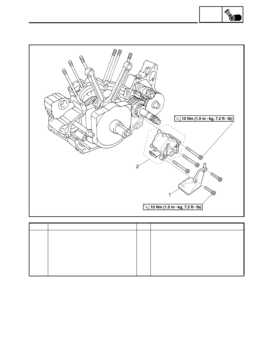
ENGINE OIL PUMP
Order
Job/Part
Q’ty
Remarks
Removing the engine oil pump
Remove the parts in the order listed.
Crankcase
Separate.
Refer to “CRANKCASE”
1
Oil strainer
1
2
Engine oil pump assembly
1
For installation, reverse the removal
procedure.