Yamaha XV1700P, XV1700PC. Service Manual - part 23
5 - 86
ENG
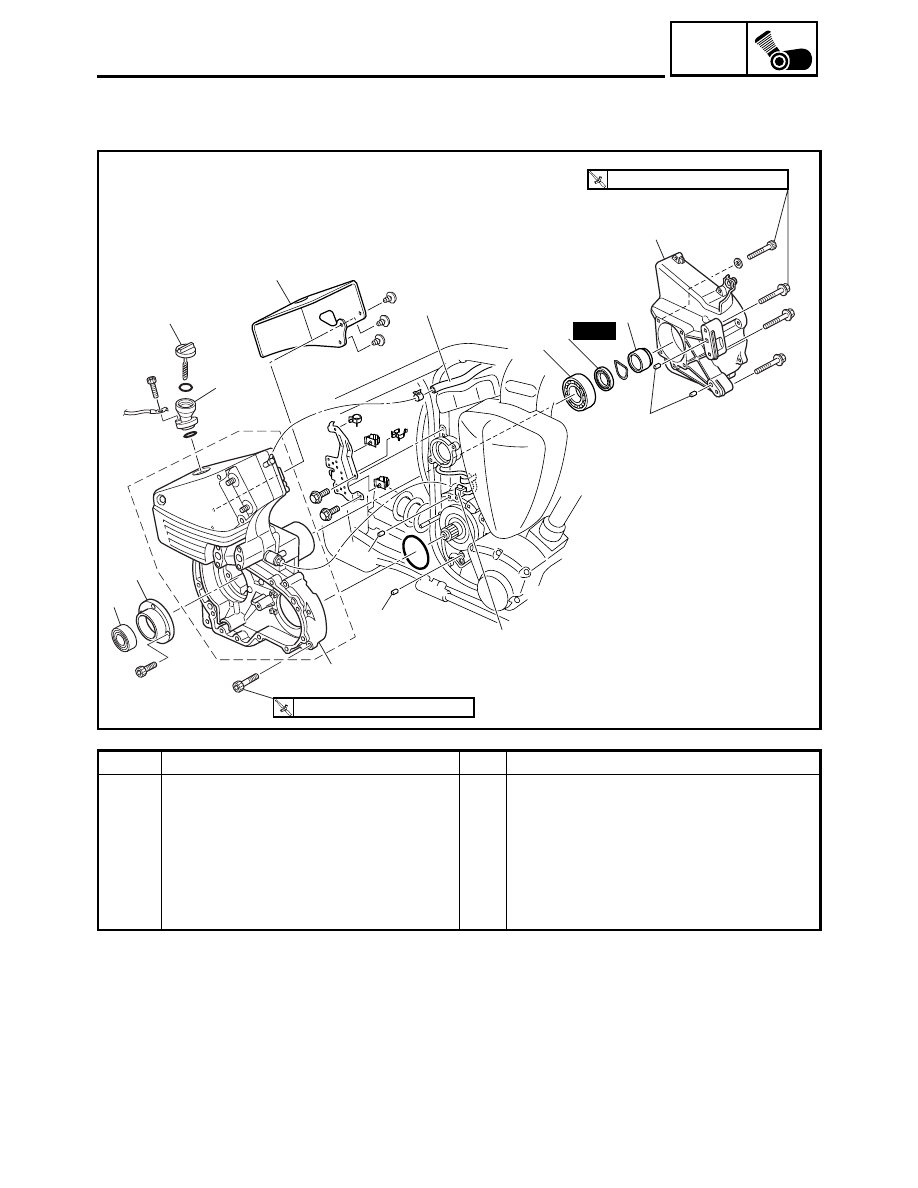
TRANSFER GEAR CASE
3
4
5
13
12
10
(4)
(4)
11
11
2
1
12
9
8
7
6
(5)
T
R
.
.
30 Nm (3.0 m
•
kg, 22 ft
•
Ib)
T
R
.
.
50 Nm (5.0 m
•
kg, 36 ft
•
Ib)
New
Order
Job/Part
Q’ty
Remarks
9
Oil seal
1
10
Transfer gear case
1
11
Dowel pin
2
12
Bearing
2
13
Bearing housing
1
For installation, reverse the removal
procedure.