Yamaha XV1700P, XV1700PC. Service Manual - part 21
5 - 54
ENG
CYLINDERS AND PISTONS
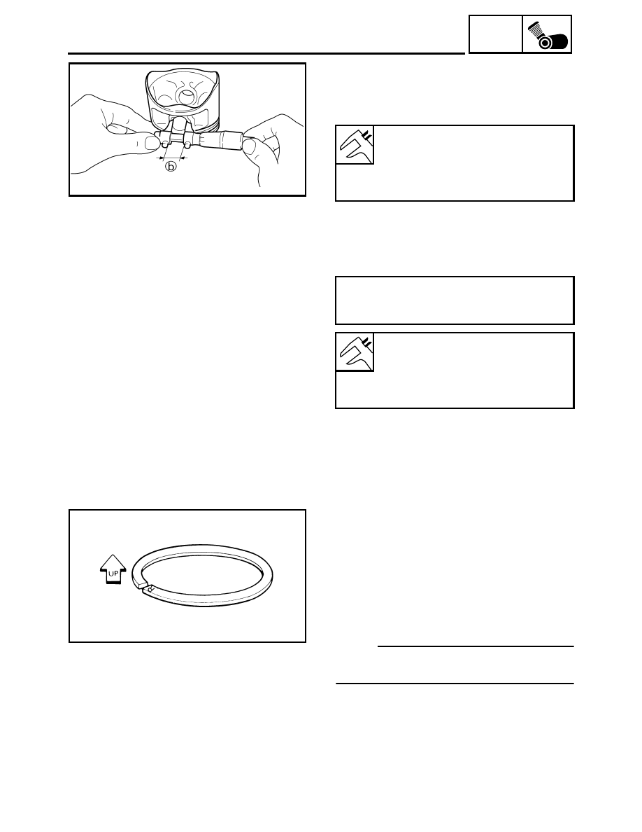
3. Measure:
• piston pin bore diameter (in the piston)
b
Out of specification
→
Replace the piston
pin.
4. Calculate:
• piston-pin-to-piston-pin-bore clearance
Out of specification
→
Replace the piston
pin and piston as a set.
Piston pin bore diameter (in the
piston)
22.004 ~ 22.015 mm
(0.8663 ~ 0.8667 in)
<Limit>: 22.045 mm (0.8679 in)
Piston-pin-to-piston clearance =
Piston pin bore diameter (in the piston)
b
- Piston pin outside diameter
a
Piston-pin-to-piston pin bore
clearance
0.004 ~ 0.024 mm
(0.00016 ~ 0.00094 in)
<Limit>: 0.074 mm (0.0029 in)
EAS00268
INSTALLING THE PISTONS AND
CYLINDERS
The following procedure applies to all of the
pistons and cylinders.
1. Install:
• top ring
• 2nd ring
• oil ring
NOTE:
_
Be sure to install the piston rings so that the
manufacturer’s marks or numbers face up.