Yamaha XV19SW(C), XV19W(C), XV19MW(C), XV19CTSW(C), XV19CTW(C), XV19CTMW(C). Service Manual - part 21
TRANSMISSION
5-112
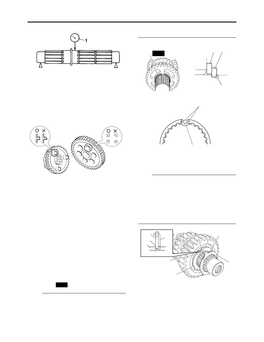
3. Check:
• Transmission gears
Blue discoloration/pitting/wear
→
Replace
the defective gear(s).
• Transmission gear dogs
Cracks/damage/rounded edges
→
Replace
the defective gear(s).
4. Check:
• Transmission gear engagement
(each pinion gear to its respective wheel
gear)
Incorrect
→
Reassemble the transmission
axle assemblies.
5. Check:
• Transmission gear movement
Rough movement
→
Replace the defective
part(s).
6. Check:
• Circlips
Bends/damage/looseness
→
Replace.
ET1D71006
ASSEMBLING THE MAIN AXLE AND DRIVE
AXLE
1. Install:
• Toothed washer “1”
• Circlip “2”
NOTE:
• Be sure the circlip sharp-edged corner “a” is
positioned opposite side to the toothed washer
and gear. (For main axle)
• Install the circlip so that both ends “b” rest on
the sides of a spline “c” with both axles aligned.
2. Install:
• Toothed lock washer retainer “1”
• Toothed lock washer “2”
NOTE:
• With the toothed lock washer retainer “1” in the
groove “a” in the axle, align the projection “c”
on the retainer with an axle spline “b”, and then
install the toothed lock washer “2”.
• Be sure to align the projection on the toothed
lock washer that is between the alignment
marks “e” with the alignment mark “d” on the
retainer.
EAS26320
INSTALLING THE SHIFT FORKS AND SHIFT
DRUM ASSEMBLY
1. Install:
• Shift forks 1 “1”
• Shift fork 2 “2”
• Shift drum assembly “3”
New
1
2
2
New
a
b
c
2
e
e
d
b
c
1
c
b
a
2
1