Yamaha XV19SW(C), XV19W(C), XV19MW(C), XV19CTSW(C), XV19CTW(C), XV19CTMW(C). Service Manual - part 19


  Index      Manuals     Yamaha XV19SW(C), XV19W(C), XV19MW(C), XV19CTSW(C), XV19CTW(C), XV19CTMW(C). Service Manual


Search            copyright infringement  


Content      ..     17      18      19      20     ..


Yamaha XV19SW(C), XV19W(C), XV19MW(C), XV19CTSW(C), XV19CTW(C), XV19CTMW(C). Service Manual - part 19


ELECTRIC STARTER

5-80

7. Check:

• Gear teeth

Damage/wear 

 Replace the gear.

8. Check:

• Bearings
• Oil seal

Damage/wear 

 Replace the defective 

part(s).

EAS24800

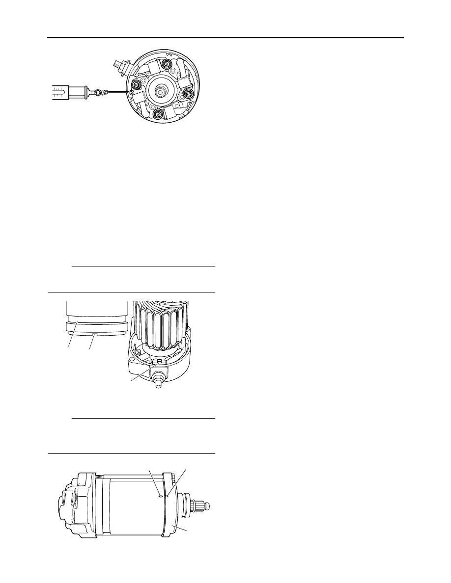
ASSEMBLING THE STARTER MOTOR

1. Install:

• Starter motor yoke “1”

NOTE:

Align the projection “a” on the brush holder with 
the slot “b” in the starter motor yoke.

2. Install:

• Starter motor front cover “1”

NOTE:

Align the match mark “a” on the starter motor 
yoke with the match mark “b” on the starter mo-
tor front cover.

1

b

a

a

b

1

-------------------------------------------------------------------------------------------------------------------------------------------------------------

TRANSFER GEAR CASE

5-81

EAS25460

TRANSFER GEAR CASE

Removing the middle driven shaft

Order

Job/Parts to remove

Q’ty

Remarks

Rider seat/Right side cover

Refer to “GENERAL CHASSIS” on page 
4-1.

Engine oil

Drain.
Refer to “CHANGING THE ENGINE OIL” on 
page 3-11.

Transfer gear oil

Drain.
Refer to “CHANGING THE TRANSFER 
GEAR OIL” on page 3-14
.

Muffler/Exhaust pipes

Refer to “ENGINE REMOVAL” on page 5-1.

Clutch release cylinder

Refer to “CLUTCH” on page 5-50.

Drive pulley

Refer to “BELT DRIVE” on page 4-80.

1

Oil pipe 2

1

2

Oil pipe 4

1

3

Transfer gear case cover

1

4

Transfer gear case gasket

1

5

Dowel pin

2

6

Transfer gear oil pump assembly

1

7

Dowel pin

2

8

6

7

1

2

3

12

10

5

5

4

9

(7)

(5)

13

New

New

7

E

New

New

New

New

New

New

11

LS

LS


R

10 Nm (1.0 m 


kg, 7.2 ft


Ib)


8 Nm (0.8 m


 kg, 5.8 ft 

 Ib)


R

18 Nm (1.8 m 


kg, 13 ft


Ib)


R

140 Nm (14.0 m 

 kg, 100 ft 

 lb)

T


R

40 Nm (4.0 m 


kg, 29 ft


Ib)

T


R

10 Nm (1.0 m 


kg, 7.2 ft


Ib)


R

10 Nm (1.0 m 


kg, 7.2 ft


Ib)

T


R

10 Nm (1.0 m 


kg, 7.2 ft


Ib)

T


R

10 Nm (1.0 m 


kg, 7.2 ft


Ib)

LT

T


R

5 Nm (0.5 m


 kg, 3.6 ft 

 Ib)

-------------------------------------------------------------------------------------------------------------------------------------------------------------

TRANSFER GEAR CASE

5-82

8

Oil strainer

1

9

Gasket

1

10

Conical spring washer

1

11

Primary chain

1

12

Middle drive gear

1

13

Middle driven shaft

1

For installation, reverse the removal proce-
dure.

Removing the middle driven shaft

Order

Job/Parts to remove

Q’ty

Remarks

8

6

7

1

2

3

12

10

5

5

4

9

(7)

(5)

13

New

New

7

E

New

New

New

New

New

New

11

LS

LS


R

10 Nm (1.0 m 


kg, 7.2 ft


Ib)


8 Nm (0.8 m


 kg, 5.8 ft 

 Ib)


R

18 Nm (1.8 m 


kg, 13 ft


Ib)


R

140 Nm (14.0 m 

 kg, 100 ft 

 lb)

T


R

40 Nm (4.0 m 


kg, 29 ft


Ib)

T


R

10 Nm (1.0 m 


kg, 7.2 ft


Ib)


R

10 Nm (1.0 m 


kg, 7.2 ft


Ib)

T


R

10 Nm (1.0 m 


kg, 7.2 ft


Ib)

T


R

10 Nm (1.0 m 


kg, 7.2 ft


Ib)

LT

T


R

5 Nm (0.5 m


 kg, 3.6 ft 

 Ib)

-------------------------------------------------------------------------------------------------------------------------------------------------------------

TRANSFER GEAR CASE

5-83

Disassembling the transfer gear oil pump

Order

Job/Parts to remove

Q’ty

Remarks

1

Transfer gear oil pump cover

1

2

Transfer gear oil pump outer rotor

1

3

Transfer gear oil pump inner rotor

1

4

Pin

1

5

Washer

1

6

Transfer gear oil pump shaft

1

7

Transfer gear oil pump housing

1

For assembly, reverse the disassembly pro-
cedure.

5

7

6

3

2

1

(6)

T


R

4 Nm (0.4 m


 kg, 2.9 ft 

 Ib)

E

4

-------------------------------------------------------------------------------------------------------------------------------------------------------------

TRANSFER GEAR CASE

5-84

Removing the transfer gear case

Order

Job/Parts to remove

Q’ty

Remarks

Horn 2 connector

Disconnect.
Refer to “ENGINE REMOVAL” on page 5-1.

Battery box

Refer to “GENERAL CHASSIS” on page 
4-1.

Sub-fuel tank

Refer to “FUEL TANK” on page 6-1.

1

Oil tank breather hose

1

Disconnect.

2

Speed sensor

1

3

Oil tank damper

1

4

Dipstick

1

5

Dipstick joint

1

6

Drive pulley case

1

7

Dowel pin

2

8

Spacer

1

9

Transfer gear case

1

10

Dowel pin

2

For installation, reverse the removal proce-
dure.

LS

LS

LS

New

New

New

New

New

3

2

10

(4)

1

7

8

4

5

9

(8)

6

LT

LT

T


R

10 Nm (1.0 m 


kg, 7.2 ft


Ib)

T


R

70 Nm (7.0 m 

 kg, 50 ft 

 lb)

T


R

50 Nm (5.0 m 


kg, 36 ft


Ib)

T


R

10 Nm (1.0 m 


kg, 7.2 ft


Ib)

LS

LS

E

E

-------------------------------------------------------------------------------------------------------------------------------------------------------------

TRANSFER GEAR CASE

5-85

Disassembling the oil tank

Order

Job/Parts to remove

Q’ty

Remarks

1

Sub-fuel tank bracket

1

2

Oil tank cover

1

3

Oil tank cover gasket

1

4

Dowel pin

2

5

Oil strainer

1

6

Oil pipe 5

1

7

Oil tank

1

For assembly, reverse the disassembly pro-
cedure.

3

2

(15)

4

5

6

1

7

New


R

10 Nm (1.0 m 


kg, 7.2 ft


Ib)

T


R

28 Nm (2.8 m 


kg, 20 ft


Ib)

T


R

10 Nm (1.0 m 


kg, 7.2 ft


Ib)

New

New


R

43 Nm (4.3 m 


kg, 31 ft


Ib)

LT

New

T


R

10 Nm (1.0 m 


kg, 7.2 ft


Ib)

LS

-------------------------------------------------------------------------------------------------------------------------------------------------------------

TRANSFER GEAR CASE

5-86

EAS25470

REMOVING THE MIDDLE DRIVEN SHAFT

NOTE:

Loosen the middle drive gear nut before remove 
the drive pulley.

1. Install:

• Right rider footrest assembly

Refer to “ENGINE REMOVAL” on page 5-1.

2. Loosen:

• Middle drive gear nut “1”

NOTE:

When loosening the middle drive gear nut, press 
down on the brake pedal so the middle drive 
gear does not move.

3. Remove:

• Primary chain “1”
• Middle drive gear “2”
• Middle driven shaft “3”

NOTE:

Remove the primary chain, middle drive gear 
and middle driven shaft at the same time.

EAS25480

CHECKING THE MIDDLE DRIVE

1. Check:

• Middle drive gear
• Middle driven gear

Damage/wear 

 Replace the middle drive 

gear, middle driven shaft and primary chain 
as a set.

2. Check:

• Primary chain

Damage/stiffness 

 Replace the primary 

chain, middle drive gear and middle driven 
shaft as a set.

EAS25490

CHECKING THE OIL STRAINER

1. Check:

• Oil strainer

Damage 

 Replace.

Contaminants 

 Clean with engine oil.

EAS25500

CHECKING THE TRANSFER GEAR OIL 
PUMP

1. Check:

• Transfer gear oil pump housing
• Transfer gear oil pump cover

Cracks/damage/wear 

 Replace the defec-

tive part(s).

2. Measure:

• Inner-rotor-to-outer-rotor-tip clearance “a”
• Outer-rotor-to-oil-pump-housing clearance 

“b”

• Oil-pump-housing-to-inner-rotor-and-outer-

rotor clearance “c”
Out of specification 

 Replace the transfer 

gear oil pump.

1

1

3

1. Transfer gear oil pump inner rotor
2. Transfer gear oil pump outer rotor
3. Transfer gear oil pump housing

-------------------------------------------------------------------------------------------------------------------------------------------------------------

TRANSFER GEAR CASE

5-87

3. Check:

• Transfer gear oil pump operation

Rough movement 

 Repeat steps (1) and 

(2) or replace the defective part(s).

EAS25510

CHECKING THE OIL PIPES

1. Check:

• Oil pipes

Damage 

 Replace.

EAS25520

ASSEMBLING THE TRANSFER GEAR OIL 
PUMP

1. Lubricate:

• Transfer gear oil pump inner rotor
• Transfer gear oil pump outer rotor
• Transfer gear oil pump shaft

(with the recommended lubricant)

2. Install:

• Transfer gear oil pump shaft “1”

(to the transfer gear oil pump housing “2”)

• Washer “3”
• Pin “4”
• Transfer gear oil pump inner rotor “5”

• Transfer gear oil pump outer rotor “6”
• Transfer gear oil pump cover “7”

NOTE:

When installing the inner rotor, align the pin in 
the oil pump shaft with the groove in the inner ro-
tor.

3. Check:

• Transfer gear oil pump operation

Refer to “CHECKING THE TRANSFER 
GEAR OIL PUMP” on page 5-86.

EAS25530

INSTALLING THE TRANSFER GEAR CASE

1. Install:

• Spacer “1”

NOTE:

Install the spacer with its groove “a” towards the 
drive pulley.

2. Install:

• Middle driven shaft “1”
• Middle drive gear “2”
• Primary chain “3”

(into the transfer gear case)

• Drive pulley nut

NOTE:

• Install the primary chain with its blue link “a” 

facing outward.


Inner-rotor-to-outer-rotor-tip 
clearance

Less than 0.12 mm (0.0047 in)

Limit

0.20 mm (0.0079 in)

Outer-rotor-to-oil-pump-housing 
clearance

0.10–0.15 mm (0.0039–0.0059 in)

Limit

0.22 mm (0.0087 in)

Oil-pump-housing-to-inner-and-
outer-rotor clearance

0.04–0.09 mm (0.0016–0.0035 in)

Limit

0.160 mm (0.0063 in)


Recommended lubricant

Engine oil

T


R

.


Oil pump housing screw

4 Nm (0.4 m·kg, 2.9 ft·lb)

3

2

1

5

6

7

(6)

4

E

1

a

-------------------------------------------------------------------------------------------------------------------------------------------------------------

TRANSFER GEAR CASE

5-88

• Install the middle drive gear “2” with its cham-

fered side facing “b” the transfer gear case.

• Install the middle driven shaft, middle drive 

gear and primary chain at the same time.

• Align the splines on the middle drive gear with 

the splines on the drive axle.

• Temporarily install the drive pulley nut onto the 

middle driven shaft.

3. Install:

• Conical spring washer “1”

• Middle drive gear nut “2” 

NOTE:

• Lubricate the middle drive gear nut threads 

and conical spring washer mating surfaces 
with engine oil.

• Install the conical spring washer “1” with the 

“OUT” mark “a” facing out.

• Stake the middle drive gear nut “2” at a cutout 

“b” in the drive axle.

4. Remove:

• Drive pulley nut

T


R

.


Middle drive gear nut

140 Nm (14.0 m·kg, 100 ft·lb)

3

1

a

b

2

New

2

New

b

1

a

-------------------------------------------------------------------------------------------------------------------------------------------------------------

CRANKCASE

5-89

EAS25540

CRANKCASE

Separating the crankcase

Order

Job/Parts to remove

Q’ty

Remarks

Engine

Refer to “ENGINE REMOVAL” on page 5-1.

Camshafts

Refer to “CAMSHAFTS” on page 5-14.

Pistons

Refer to “CYLINDERS AND PISTONS” on 
page 5-45.

Left balancer driven gear housing

Refer to “CLUTCH” on page 5-50.

Shift shaft

Refer to “SHIFT SHAFT” on page 5-70.

Generator rotor

Refer to “GENERATOR AND STARTER 
CLUTCH” on page 5-72.

1

Neutral switch

1

2

Oil pipe 3

1

3

Oil strainer

2

4

Oil delivery pipe 3

1

5

Engine oil pump driven gear stopper

1

6

Engine oil pump driven gear

1

7

Oil baffle plate (left crankcase)

1

8

Left crankcase

1

9

Dowel pin

2

New

1

11

9

4

5

6

2

(5)

7

3

13

8

9

10

12

T


R

10 Nm (1.0 m 


kg, 7.2 ft


Ib)


24 Nm (2.4 m 


kg, 17 ft


Ib)


R

10 Nm (1.0 m 


kg, 7.2 ft


Ib)


R

10 Nm (1.0 m 


kg, 7.2 ft


Ib)


R

10 Nm (1.0 m 


kg, 7.2 ft


Ib)


R

10 Nm (1.0 m 


kg, 7.2 ft


Ib)

3

New

T


R

10 Nm (1.0 m 


kg, 7.2 ft


Ib)

LS

New

LT

New

New

LS

New

New

(6)

LS

LT

LT


R

43 Nm (4.3 m 


kg, 31 ft


Ib)

(4)

LS

LT

(4)

(4)

(8)

LT

T


R

10 Nm (1.0 m 


kg, 7.2 ft


Ib)

LS

LT

-------------------------------------------------------------------------------------------------------------------------------------------------------------

CRANKCASE

5-90

10

Joint pipe

1

11

Oil pipe

1

“R” mark

12

Oil pipe

1

“F” mark

13

Right crankcase

1

For installation, reverse the removal proce-
dure.

Separating the crankcase

Order

Job/Parts to remove

Q’ty

Remarks

New

1

11

9

4

5

6

2

(5)

7

3

13

8

9

10

12

T


R

10 Nm (1.0 m 


kg, 7.2 ft


Ib)


24 Nm (2.4 m 


kg, 17 ft


Ib)


R

10 Nm (1.0 m 


kg, 7.2 ft


Ib)


R

10 Nm (1.0 m 


kg, 7.2 ft


Ib)


R

10 Nm (1.0 m 


kg, 7.2 ft


Ib)


R

10 Nm (1.0 m 


kg, 7.2 ft


Ib)

3

New

T


R

10 Nm (1.0 m 


kg, 7.2 ft


Ib)

LS

New

LT

New

New

LS

New

New

(6)

LS

LT

LT


R

43 Nm (4.3 m 


kg, 31 ft


Ib)

(4)

LS

LT

(4)

(4)

(8)

LT

T


R

10 Nm (1.0 m 


kg, 7.2 ft


Ib)

LS

LT

-------------------------------------------------------------------------------------------------------------------------------------------------------------

CRANKCASE

5-91

Removing the oil seals and bearings

Order

Job/Parts to remove

Q’ty

Remarks

Oil pump

Refer to “OIL PUMP” on page 5-95.

Crankshaft

Refer to “CRANKSHAFT” on page 5-101.

Transmission

Refer to “TRANSMISSION” on page 5-107.

1

Oil baffle plate (right crankcase)

1

2

Bearing retainer

2

3

Bearing retainer

2

4

Oil seal

2

5

Bearing

4

For installation, reverse the removal proce-
dure.

LS

4

2

1

3

3

5

5

T


R

20 Nm (2.0 m 


kg, 14 ft


Ib)

LT

New

T


R

10 Nm (1.0 m 


kg, 7.2 ft


Ib)

LT

LT


R

10 Nm (1.0 m 


kg, 7.2 ft


Ib)

New

E

LT

LT

New

E

5

5

LS

-------------------------------------------------------------------------------------------------------------------------------------------------------------

CRANKCASE

5-92

EAS25570

DISASSEMBLING THE CRANKCASE

1. Remove:

• Crankcase bolts

NOTE:

• Loosen each bolt 1/4 of a turn at a time, in stag-

es and in a crisscross pattern. After all of the 
bolts are fully loosened, remove them.

• Loosen the bolts in decreasing numerical order 

(refer to the numbers in the illustration).

• M8 

×

 90 mm bolts: “1”, “2”

• M8 

×

 65 mm bolt: “3”

• M6 

×

 100 mm bolts: “4”, “9”–“11”

• M6 

×

 80 mm bolt: “12”

• M6 

×

 70 mm bolts: “13”–“16”

• M6 

×

 60 mm bolts: “5”–“8”

• M6 

×

 35 mm bolts: “17”–“24”

2. Remove:

• Left crankcase

CAUTION:

ECA13900

Tap on one side of the crankcase with a soft-
face hammer. Tap only on reinforced por-
tions of the crankcase, not on the crankcase 
mating surfaces. Work slowly and carefully 
and make sure the crankcase halves sepa-
rate evenly.

EAS25580

CHECKING THE CRANKCASE

1. Thoroughly wash the crankcase halves in a 

mild solvent.

2. Thoroughly clean all the gasket surfaces and 

crankcase mating surfaces.

3. Check:

• Crankcase

Cracks/damage 

 Replace.

• Oil delivery passages

Obstruction 

 Blow out with compressed air.

ET1D71005

CHECKING THE BEARINGS AND OIL SEAL

1. Check:

• Bearings

Clean and lubricate the bearings, then rotate 
the inner race with your finger.
Rough movement 

 Replace.

• Oil seals

Damage/wear 

 Replace.

EAS25590

CHECKING THE OIL DELIVERY PIPE AND 
OIL PIPE

1. Check:

• Oil delivery pipe
• Oil pipes

Damage 

 Replace.

Obstruction 

 Wash and blow out with com-

pressed air.

ET1D71038

CHECKING THE OIL STRAINERS

1. Check:

• Oil strainers

Damage 

 Replace.

Contaminants 

 Clean with solvent.

A. Right crankcase
B. Left crankcase

4

1

5

3

6

7

8

A

21

20 16 15

14 19

17

18

12

10

9

22

23

13

11

24

B

-------------------------------------------------------------------------------------------------------------------------------------------------------------

CRANKCASE

5-93

EAS25610

CHECKING THE ENGINE OIL PUMP DRIVEN 
GEAR

1. Check:

• Engine oil pump driven gear

Chips/pitting/roughness/wear 

 Replace.

ET1D71034

INSTALLING THE BEARING RETAINERS

1. Install:

• Bearing retainers “1”

NOTE:

• Apply locking agent (LOCTITE

®

) to the threads 

of the bearing retainer bolts.

• Stake the bearing retainer bolts “2”.

EAS25690

ASSEMBLING THE CRANKCASE

1. Apply:

• Sealant

(onto the crankcase mating surfaces)

NOTE:

Do not allow any sealant to come into contact 
with the oil gallery.

2. Install:

• Oil pipe (“F” mark) “1”
• Oil pipe (“R” mark) “2”
• Dowel pins “3”

• Joint pipe “4”

3. Install:

• Left crankcase

(onto the right crankcase)

NOTE:

Tap lightly on the left crankcase with a soft-face 
hammer.

4. Install:

• Crankcase bolts (M6)
• Crankcase bolts (M8)

NOTE:

• Lubricate the bolt threads with engine oil.
• Tighten each bolt 1/4 of a turn at a time, in stag-

es and in a crisscross pattern.

• Tighten the bolts in numerical order (refer to 

the numbers in the illustration).

• M8 

×

 90 mm bolts: “1”, “2”

• M8 

×

 65 mm bolt: “3”

• M6 

×

 100 mm bolts: “4”, “9”–“11”

• M6 

×

 80 mm bolt: “12”

• M6 

×

 70 mm bolts: “13”–“16”

• M6 

×

 60 mm bolts: “5”–“8”

• M6 

×

 35 mm bolts: “17”–“24”


Yamaha bond No. 1215

90890-85505
(Three Bond No.1215

®

)

2

2

1

1

T


R

.


Crankcase bolt (M6)

10 Nm (1.0 m·kg, 7.2 ft·lb)

Crankcase bolt (M8)

24 Nm (2.4 m·kg, 17 ft·lb)

3

3

4

1

2

-------------------------------------------------------------------------------------------------------------------------------------------------------------

CRANKCASE

5-94

5. Apply:

• Engine oil

(onto the crankshaft pin bearings and oil de-
livery holes)

6. Check:

• Crankshaft and transmission operation

Rough movement 

 Repair.

A. Right crankcase
B. Left crankcase

4

1

5

3

6

7

8

A

21

20 16 15

14 19

17

18

12

10

9

22

23

13

11

24

B

-------------------------------------------------------------------------------------------------------------------------------------------------------------

OIL PUMP

5-95

EAS24910

OIL PUMP

Removing the oil pump

Order

Job/Parts to remove

Q’ty

Remarks

Crankcase

Separate.
Refer to “CRANKCASE” on page 5-89.

1

Oil pump assembly

1

For installation, reverse the removal proce-
dure.

1

T


R

24 Nm (2.4 m 


kg, 17 ft


Ib)

-------------------------------------------------------------------------------------------------------------------------------------------------------------


Content      ..     17      18      19      20     ..