Yamaha XV19SW(C), XV19W(C), XV19MW(C), XV19CTSW(C), XV19CTW(C), XV19CTMW(C). Service Manual - part 20
OIL PUMP
5-96
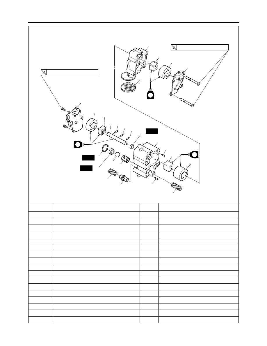
Disassembling the oil pump
Order
Job/Parts to remove
Q’ty
Remarks
1
Oil pump housing cover 1
1
2
Oil scavenging pump outer rotor 1
1
3
Oil scavenging pump inner rotor 1
1
4
Pin
1
5
Oil pump housing 1
1
6
Oil strainer
1
7
Pin
2
8
Ball spring
1
9
Oil scavenging pump outer rotor 2
1
10
Oil scavenging pump inner rotor 2
1
11
Pin
1
12
Oil pump housing cover 2
1
13
Relief valve spring
1
14
Relief valve
1
15
Oil feed pump outer rotor
1
16
Oil feed pump inner rotor
1
17
Pin
1
E
E
T
R
7 Nm (0.7 m
•
kg, 5.1 ft
•
Ib)
T
R
7 Nm (0.7 m
•
kg, 5.1 ft
•
Ib)
5
3
12
15
16
17
2
1
9
7
7
14
13
20
21
22
23
8
10
6
11
4
19
18
24
New
New
New
E