Yamaha XV19SW(C), XV19W(C), XV19MW(C), XV19CTSW(C), XV19CTW(C), XV19CTMW(C). Service Manual - part 7
ENGINE
3-10
10.Install:
• Air filter case
Refer to “GENERAL CHASSIS” on page 4-1.
• Fuel tank
Refer to “FUEL TANK” on page 6-1.
• Rider seat bracket assembly
• Rider seat
Refer to “GENERAL CHASSIS” on page 4-1.
EAS20700
CHECKING THE IGNITION TIMING
NOTE:
Prior to checking the ignition timing, check the
wiring connections of the entire ignition system.
Make sure all connections are tight and free of
corrosion.
1. Stand the vehicle on a level surface.
2. Remove:
• Shift pedal assembly “1”
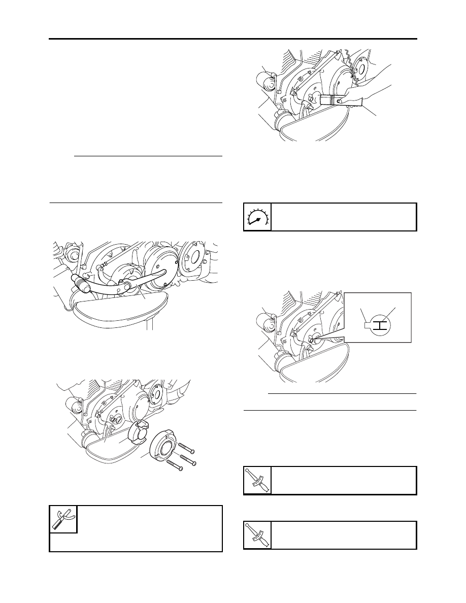
3. Remove:
• Damper cover “1”
• Damper “2”
• Timing mark accessing screw “3”
4. Connect:
• Timing light “1”
• Tachometer
5. Check:
• Ignition timing
▼▼▼
▼
▼ ▼▼▼
▼
▼ ▼▼▼
▼
▼ ▼▼▼
▼
▼ ▼▼▼
▼
▼ ▼▼▼
▼
▼▼▼
a. Start the engine, warm it up for several min-
utes, and then let it run at the specified en-
gine idling speed.
b. Check that pointer “a” on the clutch cover is
within the firing range “b” on the crankshaft
position sensor rotor.
Incorrect firing range
→
Check the ignition
system.
NOTE:
The ignition timing is not adjustable.
▲▲▲
▲
▲ ▲▲▲
▲
▲ ▲▲▲
▲
▲ ▲▲▲
▲
▲ ▲▲▲
▲
▲ ▲▲▲
▲
▲▲▲
6. Install:
• Timing mark accessing screw
• Damper
• Damper cover
7. Install:
• Shift pedal assembly “1”
Timing light
90890-03141
Inductive clamp timing light
YU-03141
1
3 2
1
Engine idling speed
850–950 r/min
T
R
.
Damper cover bolt
10 Nm (1.0 m·kg, 7.2 ft·lb)
T
R
.
Shift pedal bolt
18 Nm (1.8 m·kg, 13 ft·lb)
1
a
b