Yamaha XV19SW(C), XV19W(C), XV19MW(C), XV19CTSW(C), XV19CTW(C), XV19CTMW(C). Service Manual - part 8


  Index      Manuals     Yamaha XV19SW(C), XV19W(C), XV19MW(C), XV19CTSW(C), XV19CTW(C), XV19CTMW(C). Service Manual


Search            copyright infringement  


Content      ..     6      7      8      9     ..


Yamaha XV19SW(C), XV19W(C), XV19MW(C), XV19CTSW(C), XV19CTW(C), XV19CTMW(C). Service Manual - part 8


CHASSIS

3-26

3. Remove:

• Upper bracket

Refer to “FRONT FORK” on page 4-60.

4. Adjust:

• Steering head

▼▼▼

▼ ▼▼▼

▼ ▼▼▼

▼ ▼▼▼

▼ ▼▼▼

▼ ▼▼▼

▼▼▼

a. Remove the lock washer “1”, the upper ring 

nut “2”, and the rubber washer “3”.

b. Loosen the lower ring nut “4”, and then tight-

en it to the specified torque with a steering nut 
wrench “5”.

NOTE:

Set a torque wrench at a right angle to the steer-
ing nut wrench.

c. Loosen the lower ring nut completely, and 

then tighten it to specification with a steering 
nut wrench.

WARNING

EWA13140

Do not overtighten the lower ring nut.

d. Check the steering head for looseness or 

binding by turning the front fork all the way in 
both directions. If any binding is felt, remove 
the lower bracket and check the upper and 
lower bearings.
Refer to “STEERING HEAD” on page 4-69.

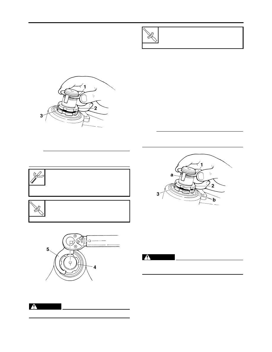
e. Install the rubber washer “3”.
f. Install the upper ring nut.
g. Finger tighten the upper ring nut “2”, then 

align the slots of both ring nuts. If necessary, 
hold the lower ring nut and tighten the upper 
ring nut until their slots are aligned.

h. Install the lock washer “1”.

NOTE:

Make sure the lock washer tabs “a” sit correctly 
in the ring nut slots “b”.

▲▲▲

▲ ▲▲▲

▲ ▲▲▲

▲ ▲▲▲

▲ ▲▲▲

▲ ▲▲▲

▲▲▲

5. Install:

• Upper bracket

Refer to “FRONT FORK” on page 4-60.

EAS21530

CHECKING THE FRONT FORK

1. Stand the vehicle on a level surface.

WARNING

EWA13120

Securely support the vehicle so that there is 
no danger of it falling over.

2. Check:

• Inner tube

Damage/scratches 

 Replace.

• Oil seal

Oil leakage 

 Replace.


Steering nut wrench

90890-01403

Spanner wrench

YU-33975

T


R

.


Lower ring nut (initial tightening 
torque)

52 Nm (5.2 m·kg, 37 ft·lb)

T


R

.


Lower ring nut (final tightening 
torque)

18 Nm (1.8 m·kg, 13 ft·lb)

-------------------------------------------------------------------------------------------------------------------------------------------------------------

CHASSIS

3-27

3. Hold the vehicle upright and apply the front 

brake.

4. Check:

• Front fork operation

Push down hard on the handlebar several 
times and check if the front fork rebounds 
smoothly.
Rough movement 

 Repair.

Refer to “FRONT FORK” on page 4-60.

EAS21590

ADJUSTING THE REAR SHOCK ABSORBER 
ASSEMBLY

WARNING

EWA13120

Securely support the vehicle so that there is 
no danger of it falling over.

Spring preload

CAUTION:

ECA13590

Never go beyond the maximum or minimum 
adjustment positions.

1. Adjust:

• Spring preload

NOTE:

Adjust the spring preload with the special 
wrench “1”.

▼▼▼

▼ ▼▼▼

▼ ▼▼▼

▼ ▼▼▼

▼ ▼▼▼

▼ ▼▼▼

▼▼▼

a. Loosen the locknut “2”.
b. Turn the adjusting ring “3” in direction “a” or 

“b”.

c. Tighten the locknut to specification.

CAUTION:

ECA13600

Always tighten the locknut against the ad-
justing nut and torque it to specification.

▲▲▲

▲ ▲▲▲

▲ ▲▲▲

▲ ▲▲▲

▲ ▲▲▲

▲ ▲▲▲

▲▲▲

EAS21650

CHECKING THE TIRES

The following procedure applies to both of the 
tires.
1. Check:

• Tire pressure

Out of specification 

 Regulate.

Direction “a”

Spring preload is increased (suspen-
sion is harder).

Direction “b”

Spring preload is decreased (suspen-
sion is softer).


Spring preload adjusting posi-
tions

Installed spring length

Minimum

162.0 mm (6.38 in)

Standard

XV19S(C)/XV19(C)/XV19M(C):
171.0 mm (6.73 in)
XV19CTS(C)/XV19CT(C)/XV19CTM(C):
165.0 mm (6.50 in)

Maximum

171.0 mm (6.73 in)

c. Installed spring length

T


R

.


Locknut (rear shock absorber 
spring preload adjusting nut)

30 Nm (3.0 m·kg, 22 ft·lb)

1

a

b

-------------------------------------------------------------------------------------------------------------------------------------------------------------

CHASSIS

3-28

WARNING

EWA13180

• The tire pressure should only be checked 

and regulated when the tire temperature 
equals the ambient air temperature.

• The tire pressure and the suspension must 

be adjusted according to the total weight 
(including cargo, rider, passenger and ac-
cessories) and the anticipated riding 
speed.

• Operation of an overloaded vehicle could 

cause tire damage, an accident or an injury.

NEVER OVERLOAD THE VEHICLE.

WARNING

EWA13190

It is dangerous to ride with a worn-out tire. 
When the tire tread reaches the wear limit, re-
place the tire immediately.

2. Check:

• Tire surfaces

Damage/wear 

 Replace the tire.

WARNING

EWA14080

• Do not use a tubeless tire on a wheel de-

signed only for tube tires to avoid tire fail-
ure and personal injury from sudden 
deflation.

• When using a tube tire, be sure to install the 

correct tube.

• Always replace a new tube tire and a new 

tube as a set.

• To avoid pinching the tube, make sure the 

wheel rim band and tube are centered in the 
wheel groove.

• Patching a punctured tube is not recom-

mended. If it is absolutely necessary to do 
so, use great care and replace the tube as 
soon as possible with a good quality re-
placement.


Tire air pressure (measured on 
cold tires)

Loading condition

0–90 kg (0–198 lb)
Front

250 kPa (36 psi) (2.50 kgf/cm²)

Rear

280 kPa (41 psi) (2.80 kgf/cm²)

Loading condition

XV19S(C)/XV19(C)/XV19M(C):
90–210 kg (198–463 lb)
XV19CTS(C)/XV19CT(C)/XV19CTM(C):
90–186 kg (198–410 lb) 
Front

250 kPa (36 psi) (2.50 kgf/cm²)

Rear

280 kPa (41 psi) (2.80 kgf/cm²)

High-speed riding

Front

250 kPa (36 psi) (2.50 kgf/cm²)

Rear

280 kPa (41 psi) (2.80 kgf/cm²)

Maximum load

XV19S(C)/XV19(C)/XV19M(C):
210 kg (463 lb)
XV19CTS(C)/XV19CT(C)/XV19CTM(C):
186 kg (410 lb)

* Total weight of rider, passenger, cargo 

and accessories


Wear limit (front)

1.0 mm (0.04 in)

Wear limit (rear)

1.0 mm (0.04 in)

1. Tire tread depth
2. Side wall
3. Wear indicator

-------------------------------------------------------------------------------------------------------------------------------------------------------------

CHASSIS

3-29

WARNING

EWA14090

After extensive tests, the tires listed below 
have been approved by Yamaha Motor Co., 
Ltd. for this model. The front and rear tires 
should always be by the same manufacturer 
and of the same design. No guarantee con-
cerning handling characteristics can be giv-
en if a tire combination other than one 
approved by Yamaha is used on this vehicle.

WARNING

EWA13210

New tires have a relatively low grip on the 
road surface until they have been slightly 
worn. Therefore, approximately 100 km 
should be traveled at normal speed before 
any high-speed riding is done.

NOTE:

For tires with a direction of rotation mark “1”:

• Install the tire with the mark pointing in the di-

rection of wheel rotation.

• Align the mark “2” with the valve installation 

point.

EAS21670

CHECKING THE WHEELS

The following procedure applies to both of the 
wheels.
1. Check:

• Wheel

Damage/out-of-round 

 Replace.

WARNING

EWA13260

Never attempt to make any repairs to the 
wheel.

NOTE:

After a tire or wheel has been changed or re-
placed, always balance the wheel.

EAS21690

CHECKING AND LUBRICATING THE 
CABLES

The following procedure applies to all of the in-
ner and outer cables.

WARNING

EWA13270

Damaged outer cable may cause the cable to 
corrode and interfere with its movement. Re-
place damaged outer cable and inner cables 
as soon as possible.

1. Check:

• Outer cable

Damage 

 Replace.

2. Check:

• Cable operation

Rough movement 

 Lubricate.

A. Tire
B. Wheel

Tube wheel

Tube tire only

Tubeless wheel

Tube or tubeless tire


Front tire

Size

130/70R18M/C 63H

Manufacturer/model

DUNLOP/D251F

Manufacturer/model

BRIDGESTONE/G851 RADIAL G


Rear tire

Size

190/60R17M/C 78H

Manufacturer/model

DUNLOP/D251

Manufacturer/model

BRIDGESTONE/G850 RADIAL G


Recommended lubricant

Engine oil or a suitable cable lu-
bricant

-------------------------------------------------------------------------------------------------------------------------------------------------------------

CHASSIS

3-30

NOTE:

Hold the cable end upright and pour a few drops 
of lubricant into the cable sheath or use a suit-
able lubricating device.

EAS21700

LUBRICATING THE LEVERS

Lubricate the pivoting point and metal-to-metal 
moving parts of the levers.

EAS21710

LUBRICATING THE PEDAL

Lubricate the pivoting point and metal-to-metal 
moving parts of the pedal.

EAS21720

LUBRICATING THE SIDESTAND

Lubricate the pivoting point and metal-to-metal 
moving parts of the sidestand.

EAS21740

LUBRICATING THE REAR SUSPENSION

Lubricate the pivoting point and metal-to-metal 
moving parts of the rear suspension.

NOTE:

Lubricate the pivoting points and contact surfac-
es between the connecting rod and frame and 
between the swingarm and frame.


Recommended lubricant

Lithium-soap-based grease


Recommended lubricant

Lithium-soap-based grease


Recommended lubricant

Lithium-soap-based grease


Recommended lubricant

Lithium-soap-based grease

-------------------------------------------------------------------------------------------------------------------------------------------------------------

ELECTRICAL SYSTEM

3-31

EAS21750

ELECTRICAL SYSTEM

EAS21760

CHECKING AND CHARGING THE BATTERY

Refer to “ELECTRICAL COMPONENTS” on 
page 7-67.

EAS21770

CHECKING THE FUSES

Refer to “ELECTRICAL COMPONENTS” on 
page 7-67.

EAS21790

REPLACING THE HEADLIGHT BULBS

1. Remove:

• Windshield (For XV19CTS(C)/

XV19CT(C)/XV19CTM(C))
Refer to “GENERAL CHASSIS” on page 4-1.

2. Remove:

• Headlight cover “1”

3. Disconnect:

• Air temperature sensor coupler “1”

4. Remove:

•  Headlight assembly “1”

5. Replace:

• Low beam headlight bulb

▼▼▼

▼ ▼▼▼

▼ ▼▼▼

▼ ▼▼▼

▼ ▼▼▼

▼ ▼▼▼

▼▼▼

a. Disconnect:

• Headlight coupler “1”

b. Remove:

• Headlight bulb “2”

WARNING

EWA13320

Since the headlight bulb gets extremely hot, 
keep flammable products and your hands 
away from the bulb until it has cooled down.

c. Install:

• Headlight bulb 

Secure the new headlight bulb with the head-
light bulb holder.

CAUTION:

ECA13690

Avoid touching the glass part of the head-
light bulb to keep it free from oil, otherwise 
the transparency of the glass, the life of the 
bulb and the luminous flux will be adversely 
affected. If the headlight bulb gets soiled, 
thoroughly clean it with a cloth moistened 
with alcohol or lacquer thinner.

d. Connect:

• Headlight coupler

▲▲▲

▲ ▲▲▲

▲ ▲▲▲

▲ ▲▲▲

▲ ▲▲▲

▲ ▲▲▲

▲▲▲

6. Replace:

• High beam headlight bulb

▼▼▼

▼ ▼▼▼

▼ ▼▼▼

▼ ▼▼▼

▼ ▼▼▼

▼ ▼▼▼

▼▼▼

a. Remove:

• Headlight bulb cover “1”

1

1

1

2

1

New

-------------------------------------------------------------------------------------------------------------------------------------------------------------

ELECTRICAL SYSTEM

3-32

b. Disconnect:

• Headlight coupler “1”

c. Detach:

• Headlight bulb holder “2”

d. Remove:

• Headlight bulb

WARNING

EWA13320

Since the headlight bulb gets extremely hot, 
keep flammable products and your hands 
away from the bulb until it has cooled down.

e. Install:

• Headlight bulb 

Secure the new headlight bulb with the head-
light bulb holder.

CAUTION:

ECA13690

Avoid touching the glass part of the head-
light bulb to keep it free from oil, otherwise 
the transparency of the glass, the life of the 
bulb and the luminous flux will be adversely 
affected. If the headlight bulb gets soiled, 
thoroughly clean it with a cloth moistened 
with alcohol or lacquer thinner.

f. Attach:

• Headlight bulb holder

g. Connect:

• Headlight coupler

h. Install:

• Headlight bulb cover

▲▲▲

▲ ▲▲▲

▲ ▲▲▲

▲ ▲▲▲

▲ ▲▲▲

▲ ▲▲▲

▲▲▲

7. Install:

• Headlight assembly

8. Connect:

• Air temperature sensor coupler

9. Install:

• Headlight cover

10.Install:

• Windshield (For XV19CTS(C)/

XV19CT(C)/XV19CTM(C))
Refer to “GENERAL CHASSIS” on page 4-1.

EAS21810

ADJUSTING THE HEADLIGHT BEAMS

1. Adjust:

• Headlight beam (vertically)

▼▼▼

▼ ▼▼▼

▼ ▼▼▼

▼ ▼▼▼

▼ ▼▼▼

▼ ▼▼▼

▼▼▼

a. Turn the adjusting bolt “1” in direction “a” or 

“b”.

▲▲▲

▲ ▲▲▲

▲ ▲▲▲

▲ ▲▲▲

▲ ▲▲▲

▲ ▲▲▲

▲▲▲

2. Adjust:

• Headlight beam (horizontally)

▼▼▼

▼ ▼▼▼

▼ ▼▼▼

▼ ▼▼▼

▼ ▼▼▼

▼ ▼▼▼

▼▼▼

a. Turn the adjusting bolt “1” in direction “a” or 

“b”.

1

2

1

New

T


R

.


Headlight cover bolt

7 Nm (0.7 m·kg, 5.1 ft·lb)

Direction “a”

Headlight beam is raised.

Direction “b”

Headlight beam is lowered.

Direction “a”

Headlight beam moves to the right.

Direction “b”

Headlight beam moves to the left.

a

b

1

-------------------------------------------------------------------------------------------------------------------------------------------------------------

ELECTRICAL SYSTEM

3-33

▲▲▲

▲ ▲▲▲

▲ ▲▲▲

▲ ▲▲▲

▲ ▲▲▲

▲ ▲▲▲

▲▲▲

a

b

1

-------------------------------------------------------------------------------------------------------------------------------------------------------------

4

CHASSIS

GENERAL CHASSIS

...................................................................................... 4-1

REMOVING THE WINDSHIELD ............................................................... 4-2
ASSEMBLING THE WINDSHIELD ........................................................... 4-2
INSTALLING THE WINDSHIELD.............................................................. 4-2
REMOVING THE BACKREST .................................................................. 4-5
ASSEMBLING THE BACKREST .............................................................. 4-5
INSTALLING THE BACKREST................................................................. 4-5
CHECKING THE SIDEBAG BRACKET SPRING NUTS........................... 4-8

FRONT WHEEL

............................................................................................ 4-15

REMOVING THE FRONT WHEEL ......................................................... 4-18
DISASSEMBLING THE FRONT WHEEL................................................ 4-18
CHECKING THE FRONT WHEEL .......................................................... 4-18
ASSEMBLING THE FRONT WHEEL...................................................... 4-19
ADJUSTING THE FRONT WHEEL STATIC BALANCE ......................... 4-19
INSTALLING THE FRONT WHEEL (FRONT BRAKE DISCS) ............... 4-20

REAR WHEEL

............................................................................................... 4-23

REMOVING THE REAR WHEEL (DISC)................................................ 4-28
DISASSEMBLING THE REAR WHEEL .................................................. 4-28
CHECKING THE REAR WHEEL ............................................................ 4-28
CHECKING THE REAR BRAKE CALIPER BRACKET........................... 4-28
CHECKING THE REAR WHEEL DRIVE HUB........................................ 4-29
CHECKING AND REPLACING THE REAR WHEEL PULLEY ............... 4-29
ASSEMBLING THE REAR WHEEL ........................................................ 4-29
ADJUSTING THE REAR WHEEL STATIC BALANCE ........................... 4-29
INSTALLING THE REAR WHEEL (DISC) .............................................. 4-29

FRONT BRAKE

............................................................................................. 4-31

INTRODUCTION..................................................................................... 4-36
CHECKING THE FRONT BRAKE DISCS............................................... 4-36
REPLACING THE FRONT BRAKE PADS .............................................. 4-37
REMOVING THE FRONT BRAKE CALIPERS ....................................... 4-38
DISASSEMBLING THE FRONT BRAKE CALIPERS ............................. 4-38
CHECKING THE FRONT BRAKE CALIPERS........................................ 4-39
ASSEMBLING THE FRONT BRAKE CALIPERS ................................... 4-39
INSTALLING THE FRONT BRAKE CALIPERS...................................... 4-39
REMOVING THE FRONT BRAKE MASTER CYLINDER....................... 4-40
CHECKING THE FRONT BRAKE MASTER CYLINDER ....................... 4-40
ASSEMBLING THE FRONT BRAKE MASTER CYLINDER ................... 4-41
INSTALLING THE FRONT BRAKE MASTER CYLINDER ..................... 4-41

-------------------------------------------------------------------------------------------------------------------------------------------------------------

REAR BRAKE

............................................................................................... 4-43

INTRODUCTION..................................................................................... 4-49
CHECKING THE REAR BRAKE DISC ................................................... 4-49
REPLACING THE REAR BRAKE PADS ................................................ 4-49
REMOVING THE REAR BRAKE CALIPER ............................................ 4-50
DISASSEMBLING THE REAR BRAKE CALIPER .................................. 4-50
CHECKING THE REAR BRAKE CALIPER............................................. 4-51
ASSEMBLING THE REAR BRAKE CALIPER ........................................ 4-51
INSTALLING THE REAR BRAKE CALIPER........................................... 4-51
REMOVING THE REAR BRAKE MASTER CYLINDER ......................... 4-52
CHECKING THE REAR BRAKE MASTER CYLINDER.......................... 4-52
ASSEMBLING THE REAR BRAKE MASTER CYLINDER ..................... 4-53
INSTALLING THE REAR BRAKE MASTER CYLINDER........................ 4-53

HANDLEBAR

................................................................................................ 4-55

REMOVING THE HANDLEBAR.............................................................. 4-57
CHECKING THE HANDLEBAR .............................................................. 4-57
INSTALLING THE HANDLEBAR ............................................................ 4-57

FRONT FORK

............................................................................................... 4-60

REMOVING THE FRONT FORK LEGS.................................................. 4-64
DISASSEMBLING THE FRONT FORK LEGS........................................ 4-64
CHECKING THE FRONT FORK LEGS .................................................. 4-65
ASSEMBLING THE FRONT FORK LEGS.............................................. 4-65
INSTALLING THE FRONT FORK LEGS ................................................ 4-68

STEERING HEAD

......................................................................................... 4-69

REMOVING THE LOWER BRACKET .................................................... 4-71
CHECKING THE STEERING HEAD....................................................... 4-71
INSTALLING THE STEERING HEAD..................................................... 4-71

REAR SHOCK ABSORBER ASSEMBLY AND SWINGARM

...................... 4-73

HANDLING THE REAR SHOCK ABSORBER........................................ 4-76
DISPOSING OF A REAR SHOCK ABSORBER ..................................... 4-76
REMOVING THE REAR SHOCK ABSORBER ASSEMBLY AND 

SWINGARM ........................................................................................... 4-76

CHECKING THE REAR SHOCK ABSORBER ASSEMBLY ................... 4-77
CHECKING THE CONNECTING ARM AND RELAY ARM..................... 4-77
CHECKING THE SWINGARM ................................................................ 4-77
INSTALLING THE RELAY ARM, REAR SHOCK ABSORBER 

ASSEMBLY AND CONNECTING ARMS............................................... 4-77

INSTALLING THE SWINGARM .............................................................. 4-79

BELT DRIVE

................................................................................................. 4-80

REMOVING THE DRIVE BELT AND DRIVE PULLEY ........................... 4-82
CHECKING THE DRIVE BELT ............................................................... 4-82
INSTALLING THE DRIVE BELT AND DRIVE PULLEY.......................... 4-82

-------------------------------------------------------------------------------------------------------------------------------------------------------------

-------------------------------------------------------------------------------------------------------------------------------------------------------------

GENERAL CHASSIS

4-1

EAS21830

GENERAL CHASSIS

Removing the windshield (For XV19CTS(C)/XV19CT(C)/XV19CTM(C))

Order

Job/Parts to remove

Q’ty

Remarks

1

Windshield

1

2

Windshield bracket brace

1

3

Windshield bracket (left and right)

2

4

Windshield brace (left and right)

2

5

Windshield screen

1

6

Windshield holder bracket assembly (left and 
right)

2

For installation, reverse the removal proce-
dure.

1

6

T


R

23 Nm (2.3 m 


kg, 17 ft


Ib)


R

23 Nm (2.3 m 


kg, 17 ft


Ib)

LT

LT

LT

LT

T


R

10 Nm (1.0 m 


kg, 7.2 ft


Ib)

T


R

10 Nm (1.0 m 


kg, 7.2 ft


Ib)

T


R

8 Nm (0.8 m


 kg, 5.8 ft 

 Ib)

6

3

3

2

4


R

12 Nm (1.2 m 


kg, 8.7 ft


Ib)


R

23 Nm (2.3 m 


kg, 17 ft


Ib)

5

-------------------------------------------------------------------------------------------------------------------------------------------------------------

GENERAL CHASSIS

4-2

ET1D71039

REMOVING THE WINDSHIELD

1. Remove:

• Windshield

▼▼▼

▼ ▼▼▼

▼ ▼▼▼

▼ ▼▼▼

▼ ▼▼▼

▼ ▼▼▼

▼▼▼

a. Insert the key “1” into the windshield lock, turn 

it clockwise and then remove the key.

b. Remove the windshield by pushing it forward, 

and then pulling it upward as shown.

WARNING

EW1D71016

Be careful not to push the vehicle forward 
when removing the windshield. The vehicle 
could fall off the sidestand.

CAUTION:

EC1D71025

Securely hold the windshield to prevent it 
from falling when removing.

▲▲▲

▲ ▲▲▲

▲ ▲▲▲

▲ ▲▲▲

▲ ▲▲▲

▲ ▲▲▲

▲▲▲

ET1D71045

ASSEMBLING THE WINDSHIELD

1. Install:

• Windshield lock “1”

NOTE:

Align the projection “a” on the lock “1” with the 
slot “b” in the windshield bracket “2”.

ET1D71040

INSTALLING THE WINDSHIELD

1. Install:

• Right windshield holder bracket assembly “1”

NOTE:

Pass the throttle cables “2” between the front 
fork and the right windshield holder bracket as-
sembly.

2. Install:

• Windshield

▼▼▼

▼ ▼▼▼

▼ ▼▼▼

▼ ▼▼▼

▼ ▼▼▼

▼ ▼▼▼

▼▼▼

a. Fit the slot “a” in each windshield bracket (left 

and right side) into its holder “b”.

NOTE:

Make sure that the throttle cables “1” are not 
pinched.

b. Push the windshield backward until it snaps 

into place.

2. Unlock.

2

1

a

1

2

b

2

1

b

a

1

-------------------------------------------------------------------------------------------------------------------------------------------------------------

GENERAL CHASSIS

4-3

c. Insert the key into the windshield lock, turn it 

counterclockwise until it stops to lock the fas-
tener, and then remove the key.

▲▲▲

▲ ▲▲▲

▲ ▲▲▲

▲ ▲▲▲

▲ ▲▲▲

▲ ▲▲▲

▲▲▲

1. Lock
2. Fastener

2

1

1

-------------------------------------------------------------------------------------------------------------------------------------------------------------

GENERAL CHASSIS

4-4

Removing the sidebags and backrest (For XV19CTS(C)/XV19CT(C)/XV19CTM(C))

Order

Job/Parts to remove

Q’ty

Remarks

1

Sidebag (left and right)

2

NOTE:

Water can be harmful to untreated leather. 
Use Yamaha Saddle Soap or another quality 
brand according to the manufacturer’s direc-
tions to clean the leather on the sidebags. 
Polish the dry leather with a soft cloth, and 
then treat with Yamaha Mink Oil or another 
high-quality leather protectant for increased 
water resistance.

2

Backrest assembly

1

3

Backrest upper bracket stay

1

4

Backrest pad

1

5

Backrest plate

2

6

Backrest upper bracket

1

7

Backrest lower bracket (left and right)

2

For installation, reverse the removal proce-
dure.

LT

1

1

2

5

7

3

6

4


R

10 Nm (1.0 m 


kg, 7.2 ft


Ib)

T


R

23 Nm (2.3 m 


kg, 17 ft


Ib)

T


R

12 Nm (1.2 m 


kg, 8.7 ft


Ib)

T


R

10 Nm (1.0 m 


kg, 7.2 ft


Ib)

LT

7

5

-------------------------------------------------------------------------------------------------------------------------------------------------------------

GENERAL CHASSIS

4-5

ET1D71041

REMOVING THE BACKREST

1. Remove:

• Backrest

▼▼▼

▼ ▼▼▼

▼ ▼▼▼

▼ ▼▼▼

▼ ▼▼▼

▼ ▼▼▼

▼▼▼

a. Open the sidebag lids.
b. Insert the key “1” into the backrest lock, turn 

it counterclockwise, and then remove the 
key.

c. Pull the lever “1” on each side of the backrest 

upward.

d. While holding the levers in the upward posi-

tion, lift the backrest upward and remove it by 
pulling it to the rear.

▲▲▲

▲ ▲▲▲

▲ ▲▲▲

▲ ▲▲▲

▲ ▲▲▲

▲ ▲▲▲

▲▲▲

ET1D71046

ASSEMBLING THE BACKREST

1. Install:

• Backrest lock “1”

NOTE:

Align the projection “a” on the lock “1” with the 
slot “b” in the left backrest lower bracket “2”.

2. Install:

• Backrest lower brackets “1”
• Backrest upper bracket “2”
• Backrest plate

NOTE:

Before tightening the bolts “3” to specification, 
temporarily install the backrest lower brackets 
on the backrest holders, making sure not to push 
down on the rear of the brackets. The lower bolts 
cannot be tightened when the backrest lower 
brackets are installed completely.

ET1D71042

INSTALLING THE BACKREST

1. Install:

• Backrest

▼▼▼

▼ ▼▼▼

▼ ▼▼▼

▼ ▼▼▼

▼ ▼▼▼

▼ ▼▼▼

▼▼▼

a. Fit the slot “a” on each backrest bracket (left 

and right side) into the groove of its holder “b”.

CAUTION:

EC1D71026

Be careful not to scratch the rear fender 
when fitting the slot into the groove.

2. Unlock.

1

1

a

1

2

b

3

1

1

2

-------------------------------------------------------------------------------------------------------------------------------------------------------------


Content      ..     6      7      8      9     ..