Yamaha YFM45FAR, YFM450FAR. Service Manual - part 13
4 - 66
ENG
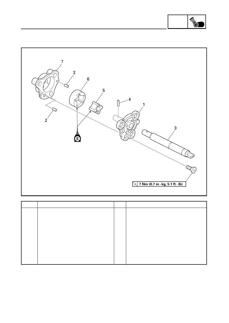
CRANKSHAFT AND OIL PUMP
OIL PUMP
Order
Job name/Part name
Q’ty
Remarks
Disassembling the oil pump
Remove the parts in the order below.
1
Rotor cover
1
2
Pin
2
3
Shaft
1
4
Pin
1
5
Inner rotor
1
6
Outer rotor
1
7
Oil pump housing
1
For assembly, reverse the disassembly
procedure.