Yamaha YFM45FAR, YFM450FAR. Service Manual - part 11
4 - 34
ENG
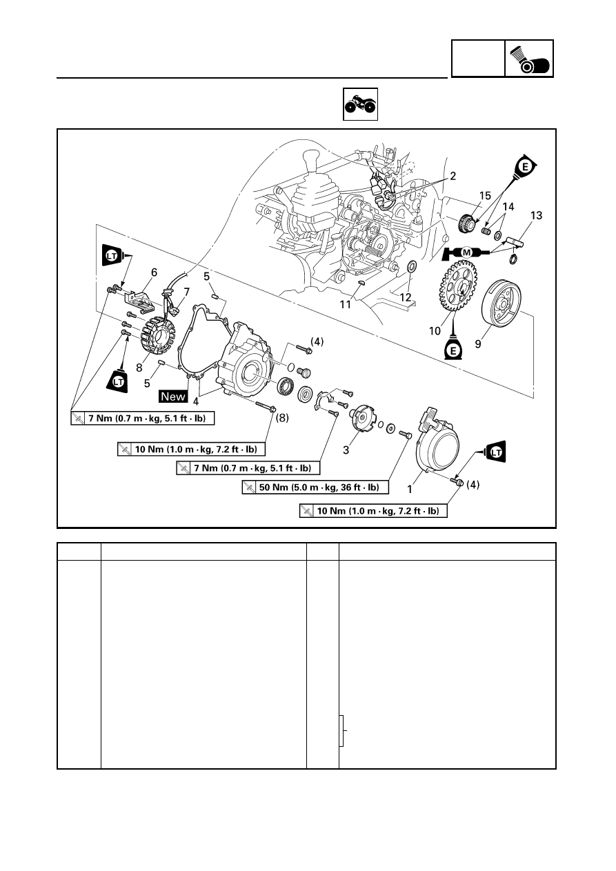
RECOIL STARTER AND A.C. MAGNETO
RECOIL STARTER AND A.C. MAGNETO
Order
Job name/Part name
Q’ty
Remarks
Removing the CDI magneto
Remove the parts in the order below.
Engine oil
Drain.
Refer to “CHANGING THE ENGINE OIL”
in CHAPTER 3.
Seat and side panels
Refer to “SEAT AND SIDE PANELS” in
CHAPTER 3.
Left footrest board
Refer to “FOOTREST BOARDS” in
CHAPTER 3.
1
Recoil starter assembly
1
2
A.C. magneto coupler
2
Disconnect.
3
Starter pulley
1
Refer to “REMOVING/INSTALLING THE
A.C. MAGNETO”.
4
Crankcase cover (left)/gasket
1/1
5
Dowel pin
2
6
Lead holder
1