Yamaha YFM45FAR, YFM450FAR. Service Manual - part 8
3 - 55
CHK
ADJ
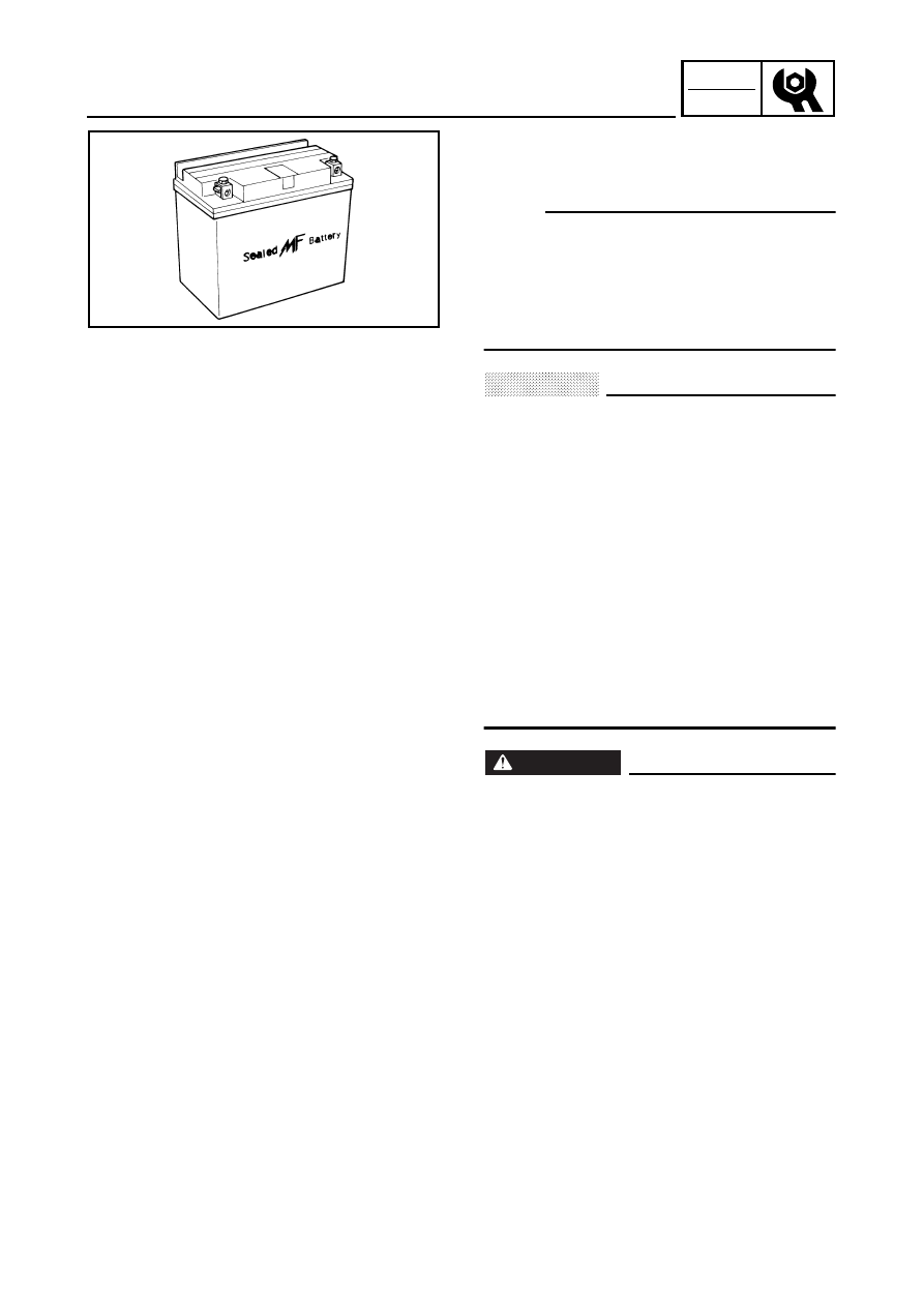
CHECKING THE BATTERY
EB305000
ELECTRICAL
CHECKING THE BATTERY
NOTE:
Since the MF battery is a sealed type battery, it
is not possible to measure the specific gravity
of the electrolyte in order to check the charge
state of the battery. Therefore, the charge of
the battery has to be checked by measuring
the voltage at the battery terminals.
CAUTION:
CHARGING METHOD
●
This is a sealed type battery. Never
remove the sealing caps. If the sealing
caps have been removed, the balance will
not be maintained and battery
performance will deteriorate.
●
Charging time, charging current and
charging voltage for the MF battery are
different from those of general type
batteries. The MF battery should be
charged as explained in “CHARGING
METHOD”. If the battery is overcharged,
the electrolyte level will drop
considerably. Therefore, take special care
when charging the battery.
WARNING
Battery electrolyte is dangerous; it
contains sulfuric acid which is poisonous
and highly caustic.
Always follow these preventive measures:
●
Avoid bodily contact with electrolyte as it
can cause severe burns or permanent eye
injury.
●
Wear protective eye gear when handling
or working near batteries.
Antidote (EXTERNAL):
●
SKIN - Wash with water.
●
EYES - Flush with water for 15 minutes
and get immediate medical attention.
Antidote (INTERNAL):
●
Drink large quantities of water or milk
followed with milk of magnesia, beaten
egg or vegetable oil. Get immediate
medical attention.