Yamaha YFM45FAR, YFM450FAR. Service Manual - part 6
3 - 23
CHK
ADJ
CHECKING THE ENGINE OIL LEVEL
CHECKING THE ENGINE OIL LEVEL
1.Place the machine on a level surface.
2.Remove:
●
Engine side panel
Refer to “SEAT, CARRIERS, FENDERS
AND FUEL TANK”.
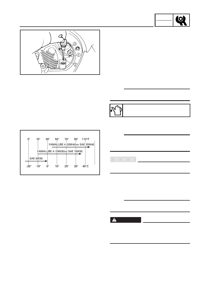
3.Check:
●
Engine oil level
Oil level should be between the maximum
level mark
1
and minimum level mark
2
.
Oil level low
→
Add oil to the proper level.
NOTE:
Do not screw the dipstick
3
in when checking
the oil level.
Recommended oil:
Follow the left chart.
NOTE:
Recommended oil classification:
API Service “SE”, “SF” type or equivalent (e.g.
“SF–SE–CC”, “SF–SE–SD” etc.)
CAUTION:
Do not allow foreign material to enter the
crankcase.
4.Start the engine and let it warm up for
several minutes.
5.Stop the engine and check the oil level
again.
NOTE:
Wait a few minutes until the oil settles before
checking the oil level.
WARNING
Never remove the dipstick just after high
speed operation because the heated oil
could spurt out. Wait until the oil cools
down before removing the dipstick.
6.Install:
●
Engine side panel