Yamaha YFM45FAR, YFM450FAR. Service Manual - part 7
3 - 39
CHK
ADJ
CHECKING THE FRONT BRAKE PAD/
CHECKING THE REAR BRAKE PAD
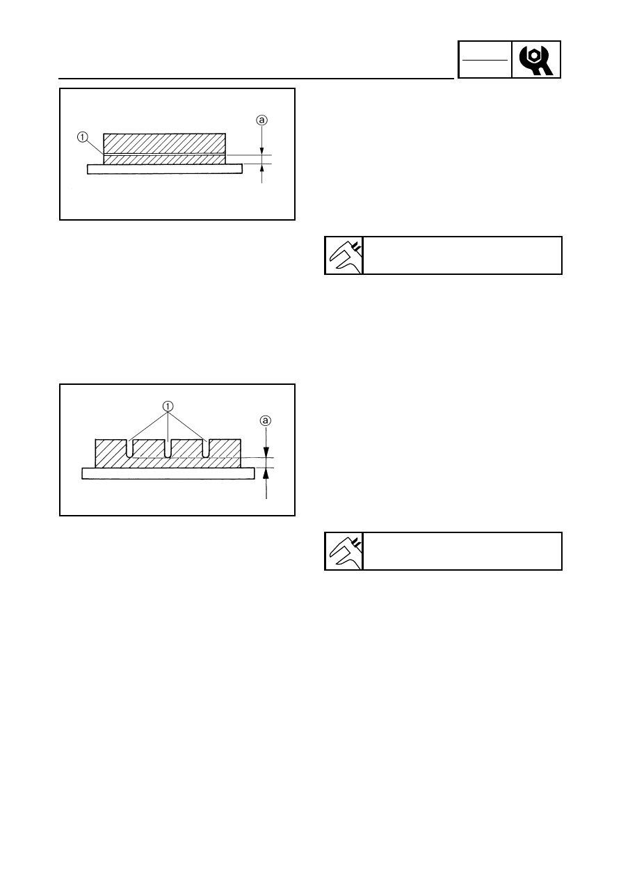
CHECKING THE FRONT BRAKE PAD
1.Remove:
●
Front wheels
2.Check:
●
Brake pad
Wear indicators groove
1
almost touch the
brake disc
→
Replace the brake pads as a
set.
Refer to “FRONT AND REAR BRAKES” in
CHAPTER 8.
3.Operate the brake lever.
4.Install:
●
Front wheels
Brake pad wear limit
a
:
1 mm (0.04 in)
CHECKING THE REAR BRAKE PAD
1.Remove:
●
Rear wheel (left)
2.Check:
●
Brake pad
Wear indicator groove
1
almost
disappeared
→
Replace the brake pads as a
set.
Refer to “FRONT AND REAR BRAKES” in
CHAPTER 8.
3.Operate the brake lever or brake pedal.
4.Install:
●
Rear wheel (left)
Brake pad wear limit
a
:
1 mm (0.04 in)