ATV Arctic Cat 2001 Line. Service Manual - part 17
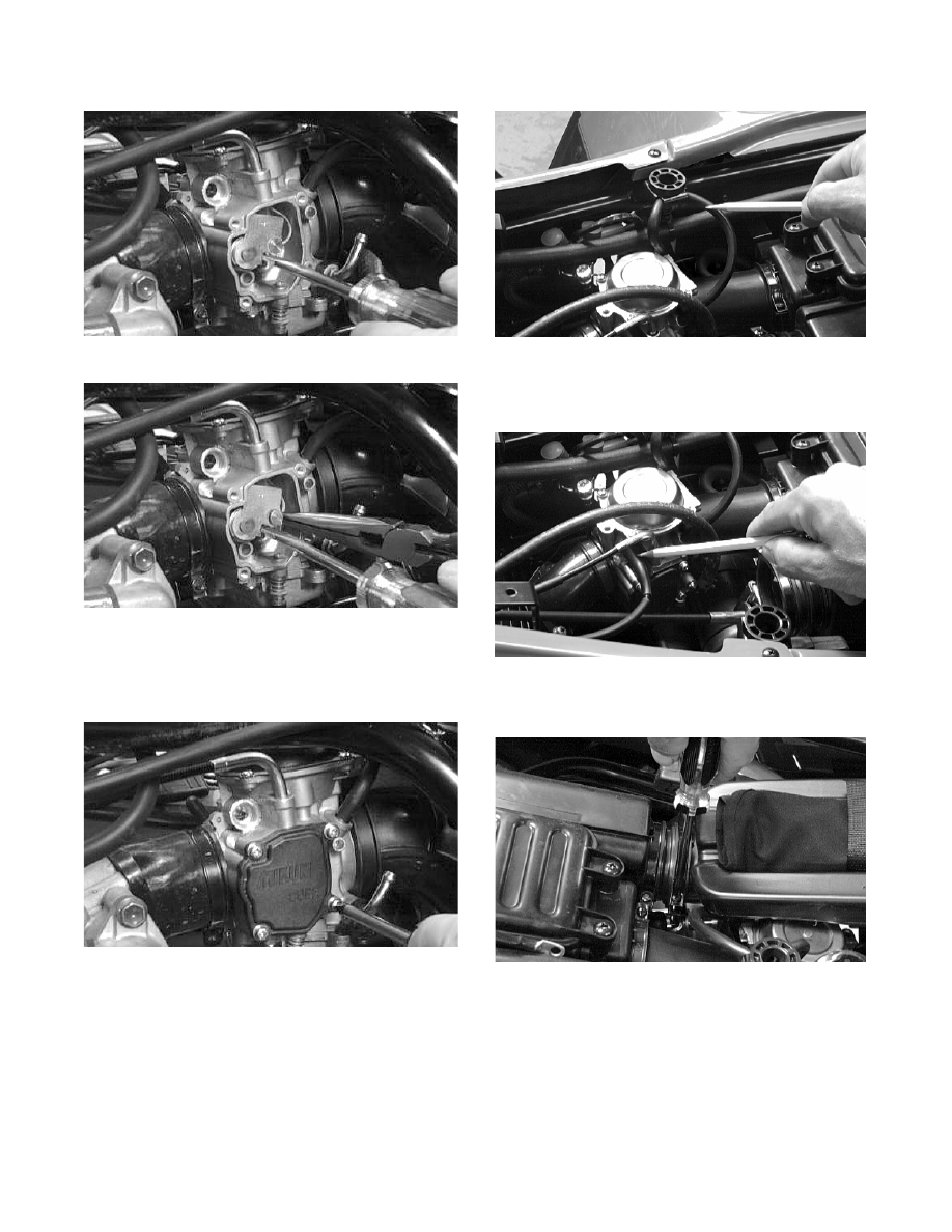
Fig. 4-45
CH022D
Fig. 4-46
CH023D
3. Place the throttle actuator cover into place and
secure with the four Phillilps-head screws (with
washer and lock washer).
Fig. 4-47
CH021D
4. Route the two vent hoses through the slots in the
frame.
Fig. 4-48
CH043D
5. Place the choke cable into position and install the
choke cable housing.
Fig. 4-49
CH042D
6. On the 250 cc, secure the air-intake snorkel.
Fig. 4-50
CH041D
4-12