ATV Arctic Cat 2001 Line. Service Manual - part 18


  Index      Manuals     ATV Arctic Cat 2001 Line. Service Manual


Search            copyright infringement  


Content      ..     16      17      18      19     ..


ATV Arctic Cat 2001 Line. Service Manual - part 18


4. Install the oil pump into the engine (see Right-Side

Components in Section 3).

Testing Oil Pump

Pressure

NOTE: The engine must be warmed up to

operating temperature for this test.

1. Connect the Arctic Cat Engine Tachometer (p/n

0644-275) to the engine.

2. Connect the Oil Pressure Gauge (p/n 0444-039) to

the oil filter drain plug.

NOTE: Some oil seepage may occur when

installing the oil pressure gauge. Wipe up oil
residue with a cloth.

3. Start the engine and run at the specified RPM.

4. The oil pressure gauge must read as specified.

250/300 cc

OIL PRESSURE @ 1275 RPM

0.7-2.8 kg/cm

2

(10-40 psi)

Oil Temperature-60°C (140°F)

400/500 cc ( Manual Transmission)

OIL PRESSURE @ 1275 RPM

1.3-1.7 kg/cm

2

(18-24 psi)

Oil Temperature-60°C (140°F)

500 cc (Automatic Transmission)

OIL PRESSURE @ 3000 RPM

1.9-2.5 kg/cm

2

(27-36 psi)

Oil Temperature-60°C (140°F)

NOTE: If the oil pressure is lower than specified,

check for an oil leak, damaged oil seal, or a defective
oil pump.

NOTE: If the oil pressure is higher than specified,

check for too heavy engine oil weight (see
Section 2), clogged oil passage, clogged oil filter, or
improper installation of the oil filter.
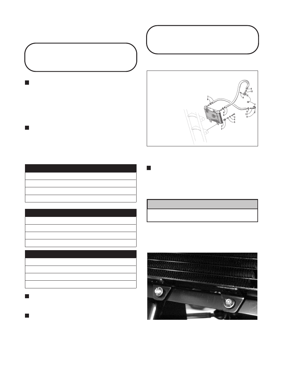
Oil Cooler

(250/300 cc)

Fig. 4-114

0733-727

REMOVING

NOTE: It is not necessary to drain the engine oil

for this procedure.

1. Remove the input and output hoses from the fittings

on the cooler.

Elevate and secure the hoses to avoid oil
spillage.

2. Remove the torx-head screws securing the oil

cooler to the frame. Account for grommets, collars,
and washers.

Fig. 4-115

AL651D

3. Remove the oil cooler from the frame.

KEY

1. Oil Cooler
2. Grommet
3. Cap Screw
4. Washer
5. Collar
6. Hose Clamp
7. Hose (Output)
8. Hose (Input)
9. Cap Screw

10. O-Ring
11. Fitting (Angled)
12. Fitting

! CAUTION

4-28

-------------------------------------------------------------------------------------------------------------------------------------------------------------

INSTALLING

1. Place the collar into position in the frame.

2. Secure the cooler to the frame with the torx-head

screws, washers, collars, and spacers.

Fig. 4-116

AL651D

3. Install the hoses onto their respective fittings and

secure with the clamps.

Liquid Cooling System

(400/500 cc)

Fig. 4-117

0735-912

KEY

1. Radiator Screen
2. Wire Clamp
3. Cap Screw
4. Grommet
5. Collar
6. Hose
7. Radiator Cap
8. Radiator Assy
9. Hose Clamp

10. Radiator
11. Hose Clamp
12. Coolant Hose
13. Fan Blade
14. Fan Motor
15. Machine Screw
16. Coolant Hose
17. Coolant Hose
18. Machine Screw
19. Washer
20. Fender Panel
21. Thumb Screw
22. Speed Nut
23. Nut
24. Washer
25. Stem Bushing
26. Machine Screw
27. Cable Tie
28. Fan Shroud
29. Fender Panel
30. Flange Nut

400/500 cc
(Manual Transmission)

4

4-29

-------------------------------------------------------------------------------------------------------------------------------------------------------------

Fig. 4-118

0735-528

The cooling system capacity is approximately 2.9 L (3
U.S. qt). The cooling system should be inspected daily
for leakage and damage. Also, the coolant level should
be checked periodically.

When filling the cooling system, use premixed Arctic
Cat Antifreeze (p/n 0638-395). While the cooling
system is being filled, air pockets may develop;
therefore, run the engine for five minutes after the initial
fill, shut the engine off, and then fill the cooling system
to 1/2 in. above the radiator core.

Fig. 4-119

AN604D

After operating the ATV for the initial 5-10
minutes, stop the engine, allow the engine to
cool  down, and  check the coolant level. Add
coolant as necessary.

Radiator

Fig. 4-120

0732-411

REMOVING

1. Drain the coolant at the engine.

2. Remove the front rack (see Section 8).

3. Remove the front fenders (see Section 8).

4. Remove the four machine screws securing  the

fender panels to the radiator.

KEY

1. Radiator Screen
2. Wire Clamp
3. Cap Screw
4. Grommet
5. Collar
6. Vent Hose
7. Radiator Cap
8. Radiator Assy
9. Radiator

10. Clamp
11. Coolant Hose
12. Fan Blade
13. Fan Motor
14. Machine Screw
15. Coolant Hose
16. Coolant Hose
17. Washer
18. Fan Shroud
19. Thumb Screw
20. Speed Nut
21. Nut
22. Washer
23. Stem Bushing
24. Machine Screw
25. Cable Tie
26. Cable Tie
27. Flange Nut

500 cc
(Automatic Transmission)

! CAUTION

4-30

-------------------------------------------------------------------------------------------------------------------------------------------------------------

Fig. 4-121

AF622D

5. Remove the upper and lower coolant hoses.

Fig. 4-122

AF734D

6. Remove the two cap screws securing the radiator to

the frame.

7. Remove the radiator and account for the two

grommets with collar inserts.

CLEANING AND INSPECTING

NOTE: Whenever a part is worn excessively,

cracked, or damaged in any way, replacement is
necessary.

1. Flush the radiator with water to remove any

contaminants.

2. Inspect the radiator for leaks and damage.

3. Inspect all hoses for cracks and deterioration.

4. Inspect all fasteners and grommets for damage or

wear.

INSTALLING

1. Place the radiator with grommets and collar inserts

into position on the frame; then install the two cap
screws. Tighten securely.

2. Install  the upper and  lower coolant hoses;  then

secure with hose clamps.

Fig. 4-123

AF734D

3. Place the fan shroud into position on the radiator;

then install the four machine screws and tighten to
0.7 kg-m (5 ft-lb).

Fig. 4-124

AF622D

4. Install the front fenders (see Section 8).

5. Install the front rack (see Section 8).

6. Fill the cooling system (2.9 L or 3 U.S. qt) with

antifreeze. Check for leakage.

Fig. 4-125

AN602D

4

4-31

-------------------------------------------------------------------------------------------------------------------------------------------------------------

Hoses/Thermostat

REMOVING

1. Drain the coolant from the cooling system.

2. Remove the hose clamps securing the lower coolant

hose to the water pump housing and to the radiator;
then remove the lower hose.

Fig. 4-126

CC334D

3. Remove the clamps securing the upper coolant hose

to the thermostat housing and to the radiator; then
remove the upper hose.

Fig. 4-127

CC335D

4. Remove the clamps securing the crossover coolant

hose to the water pump and to the engine water
inlet.

5. Remove the two cap screws securing the thermostat

housing to the cylinder head. Account for an O-ring
and a thermostat.

INSPECTING

NOTE: Whenever a part is worn excessively,

cracked, or damaged in any way, replacement is
necessary.

1. Inspect the thermostat for corrosion, wear, or spring

damage.

2. Using the following procedure, inspect the

thermostat for proper operation.

A. Suspend the thermostat in a container filled with

water.

B. Heat the water and monitor the temperature with a

thermometer.

C. The thermostat should start to open at 48.5-51.5°C

(119.3-124°F).

D. If the thermostat does not open, it must be

replaced.

3. Inspect all coolant hoses, connections, and clamps

for deterioration, cracks, and wear.

NOTE: All coolant hoses and clamps should be

replaced every four years or 4000 miles.

INSTALLING

1. Place the thermostat and O-ring into the thermostat

housing; then secure the thermostat housing to the
cylinder head with the two cap screws.

2. Install the crossover coolant hose onto the water

pump and engine water inlet. Secure with the two
hose clamps.

3. Slide the upper hose onto the thermostat housing

and radiator. Secure with the two hose clamps.

Fig. 4-128

CC335D

4. Install the lower coolant hose onto the water pump

housing and radiator. Secure with the two hose
clamps.

4-32

-------------------------------------------------------------------------------------------------------------------------------------------------------------

Fig. 4-129

CC334D

5. Fill the cooling system (2.9 L or 3 U.S. qt) with

antifreeze. Check for leakage.

Fan

REMOVING

NOTE: It is not necessary to drain the cooling

system or to remove any coolant hoses for this
procedure.

1. Remove the left-hand-threaded  nut and washer

securing the fan blade to the fan motor. Account for
a shaft pin.

Fig. 4-130

AF642D

Fig. 4-131

AF641D

2. Remove the three machine screws securing the fan

motor to  the  frame; then  disconnect  the  wiring
harness.

Fig. 4-132

AF640D

3. Slide the fan motor rearward out of the frame.

INSTALLING

1. Place the fan motor into position in the frame; then

connect the wiring harness.

2. Secure the fan motor to the frame with the three

machine screws.

Fig. 4-133

AF640D

4

4-33

-------------------------------------------------------------------------------------------------------------------------------------------------------------

3. Place the fan blade with shaft pin onto the motor

and secure with the left-hand-threaded nut (threads
coated with blue Loctite #242) and washer. Tighten
to 0.4 kg-m (3 ft-lb).

Fig. 4-134

AF642D

Servicing Water Pump

(400/500 cc -

Manual Transmission)

REMOVING/DISASSEMBLING

Fig. 4-135

0732-311

1. Drain the coolant.

2. Remove the three cap screws securing the water

pump case. Note the position of the long cap screw
and account for the O-ring.

3. Remove the impeller cap screw, washer, and gasket.

4. Remove the mechanical seal using this procedure.

A. Tap the tip of a small sheet metal screw into the

inner-metal edge of the seal.

B. Grip the screw with a pair of vise-grip pliers and

pull the seal out. Account for the pump drive seal.

CLEANING AND INSPECTING

NOTE: Whenever a part is worn excessively,

cracked, or damaged in any way, replacement is
necessary.

1. Clean all pump components in solvent.

2. Inspect the mechanical seal and pump drive seal for

damage.

NOTE: If the mechanical seal and/or pump drive

seal are damaged, they must be replaced as a set.

3. Inspect the impeller for corrosion or damage.

ASSEMBLING/INSTALLING

NOTE: Treat seals and O-rings with clean

antifreeze for initial lubrication.

1. Press the mechanical seal with pump drive seal into

the impeller by hand.

2. Install the mechanical seal assembly onto the water

pump shaft and secure with the cap screw, washer,
and gasket. Tighten the cap screw to 1.05 kg-m (7.5
ft-lb).

3. Place the water pump case into position and secure

with the three cap screws. Note the position of the
long cap screw from removal.

4. Fill the cooling system (2.9 l or 3 U.S. qt) with

antifreeze.

NOTE: While the cooling system is being filled, air

pockets may develop; therefore, run the engine for
five minutes after the initial fill, shut the engine off,
and then fill the cooling system to 1/2 in. above the
radiator core.

5. Check the entire cooling system for leakage.

KEY

1. Case
2. Cap Screw
3. Gasket
4. O-Ring
5. Cap Screw
6. Cap Screw
7. Joint
8. Shaft w/Bearing
9. Pin

10. Pump Drive Seal
11. Mechanical Seal
12. Impeller
13. Cap Screw
14. Washer
15. Gasket

4-34

-------------------------------------------------------------------------------------------------------------------------------------------------------------

Servicing Water Pump

(500 cc - Automatic

Transmission)

NOTE: When servicing the water pump, it will be

necessary to install a new Oil Seal (p/n 3402-465)
and a new Mechanical Seal/Ceramic Seal Assembly
(p/n 3402-360).

Fig. 4-136

735-616A

REMOVING

1. Remove the radiator cap; then remove the water

pump drain plug and drain the coolant.

Fig. 4-137

CC789

2. Drain the oil from the engine/transmission.

3. Remove the four torx-head cap screws securing the

front and rear fenders to the footrest; then remove
the four cap screws and nuts securing the footrest to
the frame. Remove the footrest.

Fig. 4-138

CC787A

4. From inside the left-front wheel-well, remove the

two torx-head cap screws securing the fender to the
frame.

KEY

1. Water Pump Assy
2. Bolt
3. Gasket
4. O-Ring
5. Impeller/Shaft
6. Mechanical Seal/Ceramic Seal Assy
7. Oil Seal
8. Bearing
9. E-Ring

10. O-Ring
11. Screw
12. Cap Screw

4

4-35

-------------------------------------------------------------------------------------------------------------------------------------------------------------

Fig. 4-139

CC788A

5. Compress the tabs on the coolant hose clamps and

slide the clamps away from the hose ends
approximately 51 mm (2 in.); then remove both
hoses from the water pump.

Fig. 4-140

CC784

6. Using an impact driver, loosen but do not remove

the two Phillips-head water pump cover screws.

Fig. 4-141

CC785A

7. Remove the two cap screws securing the water

pump to the engine; then remove the water pump.

Fig. 4-142

CC786A

DISASSEMBLING

1. Finish removing the two Phillips-head cap screws

securing the cover to the bearing housing; then
remove the cover. Account for the O-ring.

2. Remove the E-ring securing the impeller/shaft to

the bearing housing; then remove the impeller/shaft.

Fig. 4-143

CC781

3. Using Seal Removal Tool (p/n 0644-072), remove

the mechanical seal and the oil seal from the bearing
housing.

Fig. 4-144

CC772

4-36

-------------------------------------------------------------------------------------------------------------------------------------------------------------

4. Using a small screwdriver, pry up and remove the

ceramic seal from the impeller/shaft; then remove
the seal seat.

Fig. 4-145

CC773

Fig. 4-146

CC775

CLEANING AND INSPECTING

NOTE: Whenever a part is worn excessively,

cracked, or damaged in any way, replacement is
necessary.

1. Clean all oil-pump components in cleaning solvent.

2. Inspect the impeller/shaft for corrosion or damage.

ASSEMBLING

1. Place the new oil seal into the bearing housing; then

using a seal driver, gently tap the seal down until it
is fully seated.

Fig. 4-147

CC778

2. Place the new mechanical seal into the bearing

housing; then tap it down until it is fully seated.

NOTE: A large deep-well socket can be used to

drive the seal down evenly.

3. Using the protective cloth provided, slide the new

ceramic seal (red markings down) and seal seat onto
the impeller/shaft. Touch the assembly ONLY with
the protective cloth provided.

If the protective cloth is not used and the
seal/seat assembly is touched, permanent
damage to the assembly will occur and
replacement will be necessary.

Fig. 4-148

CC776

4. Install the impeller/shaft assembly into the bearing

housing; then secure with the E-ring.

! CAUTION

4

4-37

-------------------------------------------------------------------------------------------------------------------------------------------------------------

Fig. 4-149

CC781

NOTE: Make sure the E-ring is fully seated and the

impeller rotates freely.

5. While holding the  bearing  housing assembly in

position on the engine, slowly rotate the impeller
until the impeller/shaft engages properly with its
slot in the driven shaft.

NOTE: The bearing housing will be flush with the

engine when the two shafts are properly engaged.

Failure to properly engage the two shafts could
cause serious engine damage.

6. With the bearing housing assembly in position on

the engine, place the cover (with O-ring installed)
into position on the housing; then loosely secure
with the two Phillips-head cap screws.

INSTALLING

1. Secure the water pump to the engine with the two

cap screws tightened securely; then tighten the two
Phillips-head cap screws securely.

Fig. 4-150

CC786A

Fig. 4-151

CC785A

2. Connect the two coolant hoses to the water pump

and secure with the clamps.

Fig. 4-152

CC784

3. From inside the left-front wheel-well, secure the

fender to the frame with the two torx-head cap
screws. Tighten securely.

Fig. 4-153

CC788A

4. Place the footrest into position on the frame and

loosely secure with four cap screws and nuts; then
secure the front and rear fenders to the footrest with
the four torx-head cap screws. Tighten the four
torx-head cap screws securely; then tighten the four
cap screws and nuts to 2.8 kg-m (20 ft-lb).

! CAUTION

4-38

-------------------------------------------------------------------------------------------------------------------------------------------------------------

Fig. 4-154

CC787A

5. Fill the engine/transmission with the proper amount

of recommended oil.

6. Fill the cooling system with the proper amount of

recommended coolant.

Fig. 4-155

AN604D

NOTE: While the cooling system is being filled, air

pockets may develop; therefore, run the engine for
five minutes after the initial fill, shut the engine off,
and then fill the cooling system to 1/2 in. above the
radiator core.

7. Check the entire cooling system for leakage.

After operating the ATV for the initial 5-10
minutes, stop the engine, allow the engine to
cool  down, and check the coolant level. Add
coolant as necessary.

! CAUTION

4

4-39

+


Click Here to Continue

-------------------------------------------------------------------------------------------------------------------------------------------------------------

-------------------------------------------------------------------------------------------------------------------------------------------------------------

SECTION 5 - ELECTRICAL SYSTEM

TABLE OF

CONTENTS

Specifications . . . . . . . . . . . . . . . . . .  5-2
Battery . . . . . . . . . . . . . . . . . . . . .  5-3
RPM Limiter . . . . . . . . . . . . . . . . . . .  5-3
Testing Electrical Components . . . . . . . . .  5-4
Accessory Receptacle/Connector (400/500 cc) 5-4
Brakelight Switch (Foot) . . . . . . . . . . . .  5-4
Brakelight Switch (Handlebar Control) . . . . .  5-5
Oil Temperature Switch (250/300 cc) . . . . . .  5-6
Fan Motor (400/500 cc) . . . . . . . . . . . . .  5-6
Fuse Block . . . . . . . . . . . . . . . . . . .  5-7
Fuses . . . . . . . . . . . . . . . . . . . . . .  5-8
Gear Position Lights (300 cc 4x4/

400/500 cc - Manual Transmission) . . . . .  5-8

Gear Position Switch (Manual Transmission) . . 5-9
Ignition Coil . . . . . . . . . . . . . . . . . . . 5-10
Indicator Lights . . . . . . . . . . . . . . . . . 5-11
Ignition Switch . . . . . . . . . . . . . . . . . 5-13
Handlebar Control Switches . . . . . . . . . . 5-13
Magneto Assembly . . . . . . . . . . . . . . . 5-14
Starter Motor . . . . . . . . . . . . . . . . . . 5-15
Starter Relay (250/300 cc) . . . . . . . . . . . 5-21
Starter Relay (400/500 cc) . . . . . . . . . . . 5-22
CDI Unit (250/300 cc) . . . . . . . . . . . . . . 5-23
Regulator/Rectifier (250/300 cc) . . . . . . . . 5-23
CDI Unit (400/500 cc) . . . . . . . . . . . . . . 5-24
Regulator/Rectifier (400/500 cc) . . . . . . . . 5-25
Neutral Start Relay . . . . . . . . . . . . . . . 5-26
Headlights . . . . . . . . . . . . . . . . . . . . 5-27
Taillight - Brakelight . . . . . . . . . . . . . . . 5-27
Ignition Timing . . . . . . . . . . . . . . . . . 5-28
Wiring Diagrams . . . . . . . . . . . . . . . . 5-29

5

5-1

+


Click Here to Go Back

-------------------------------------------------------------------------------------------------------------------------------------------------------------

Specifications

250 cc

IGNITION

Ignition Timing

5° BTDC below 1800 RPM
35° BTDC above 3800 RPM

Spark Plug Type

NGK DR7EA

Spark Plug Gap

0.6-0.7 mm
(0.024-0.028 in.)

Spark Plug Cap

8000-12,000 ohms

Ignition Coil Resistance

(primary)

(secondary)

0.1-0.5 ohm
(terminal to ground)
5200-7800 ohms
(high tension - plug cap
removed - to ground)

MAGNETO

Magneto Coil Resistance

(trigger)

(charging)

90-140 ohms
(Black/Yellow to Green/White)
0.1-1.0 ohm
(Yellow to Yellow)

Magneto Output (approx) 220W @ 5000 RPM

300 cc

IGNITION

Ignition Timing

5° BTDC @ 1800 RPM
30° BTDC @ 3800 RPM

Spark Plug Type

NGK DR7EA

Spark Plug Gap

0.6-0.7 mm
(0.024-0.028 in.)

Spark Plug Cap

8000-12,000 ohms

Ignition Coil Resistance

(primary)

(secondary)

0.1-0.5 ohm
(terminal to ground)
5200-7800 ohms
(high tension - plug cap
removed - to ground)

MAGNETO

Magneto Coil Resistance

(trigger)

(charging)

90-140 ohms
(Black/Yellow to Green/White)
0.1-1.0 ohm
(Yellow to Yellow)

Magneto Output (approx) 220W @ 5000 RPM

400 cc

IGNITION

Ignition Timing

10° BTDC @ 1500 RPM

Spark Plug Type

NGK CR6E

Spark Plug Gap

0.7-0.8 mm
(0.028-0.032 in.)

Spark Plug Cap

8000-12,000 ohms

Ignition Coil

Resistance

(primary)

(secondary)

0.1-1.0 ohm (terminal to
ground)
12,000-30,000 ohms
(high tension - plug cap
removed - to ground)

MAGNETO

Magneto Coil Resistance

(trigger)

(source/charge)

(charging)

150-300 ohms
(Green to Blue)
0.05-1.0 ohm
(Yellow to White)
0.1-1.0 ohm
(Black to Black)

Magneto Output (approx) 340W @ 5000 RPM

500 cc

IGNITION

Ignition Timing

10° BTDC @ 1500 RPM

Spark Plug Type

NGK CR6E

Spark Plug Gap

0.7-0.8 mm
(0.028-0.032 in.)

Spark Plug Cap

8000-12,000 ohms

Ignition Coil

Resistance

(primary)

(secondary)

0.1-0.8 ohm (terminal to
ground)
10,000-15,000 ohms
(high tension - plug cap
removed - to ground)

MAGNETO

Magneto Coil Resistance

(trigger)

(source/charge)

(charging)

170-250 ohms
(Green to Blue)
160-240 ohms*
(Green to Blue)
0.05-1.0 ohm
(Yellow to White)
0.1-1.0 ohm
(Black to Black)

Magneto Output (approx) 325W @ 5000 RPM

*Automatic Transmission Model

5-2

-------------------------------------------------------------------------------------------------------------------------------------------------------------

Battery

! WARNING

Anytime service is performed on a battery, the
following must be observed: keep sparks, open
flame,  cigarettes, or any other flame away.
Always wear safety glasses. Protect skin and
clothing when handling a battery. When
servicing battery in enclosed space, keep the
area well-ventilated. Make sure venting tube of
battery is always open once battery is filled with
electrolyte.

1. Remove the battery from the ATV.

! WARNING

Remove the negative cable first; then remove the
positive cable.

Do not charge the battery while it is in the ATV
with the battery terminals connected.

2. Remove the vent plugs; then fill the battery with

electrolyte to the UPPER level indicated on the
battery.

NOTE: Electrolyte should be at room temperature

before filling. Do not use water or any other liquid to
activate a battery.

! WARNING

Electrolyte is a sulfuric acid solution. Avoid
spillage and contact with skin, eyes, and
clothing.

3. Allow the battery to stand for 15-30 minutes after

filling. Electrolyte level may fall during this time.
Refill with electrolyte to UPPER level line.

4. Trickle-charge the battery at 1.4 amps for 8-10

hours.

5. After charging, check electrolyte level and fill with

DISTILLED WATER

as necessary; then install

the vent plugs. Wash off acid spillage with water
and dry the battery.

Before installing the battery, make sure the
ignition switch is in the OFF position.

6. Place the  battery into  position  in the  ATV and

secure.

7. Connect cables to the proper terminals: positive

cable to the positive terminal (+) and negative cable
to the negative terminal (-). Connect the negative
cable last.

Connecting cables in reverse (positive to
negative and negative to positive) can cause
serious damage to the electrical system.

8. Check the vent tube to make sure it is not pinched

or obstructed in any way and that it is properly
routed down through the frame.

RPM Limiter

The ATV has an RPM limiter system to limit the engine
RPM. One way to eliminate the activation of the RPM
limiter is to utilize the throttle limiter screw at the
throttle lever.

NOTE: The ATV is equipped with a CDI unit that

retards ignition timing when maximum RPM is
approached. When the RPM limiter is activated, it
could be misinterpreted as a high-speed misfire.

1. Ensure that the throttle cable is adjusted correctly at

3-6 mm (1/8-1/4 in.) free-play at the lever.

Fig. 5-1

ATV-0047

2. Loosen the jam nut of the limiter screw and rotate

the screw clockwise until RPM is limited to under
9000 RPM (250/300 cc) or under 8300 RPM
(400/500 cc); then tighten the jam nut.

! CAUTION

! CAUTION

! CAUTION

5

5-3

-------------------------------------------------------------------------------------------------------------------------------------------------------------


Content      ..     16      17      18      19     ..