ATV Arctic Cat 2001 Line. Service Manual - part 4


  Index      Manuals     ATV Arctic Cat 2001 Line. Service Manual


Search            copyright infringement  


Content      ..     2      3      4      5     ..


ATV Arctic Cat 2001 Line. Service Manual - part 4


NOTE: The brake pads should be replaced as a

set.

Installing

1. Place the brake pads into the caliper.

NOTE: The metal backing of the pad will be facing

the adjuster arms when installed properly.

2. Slide brake caliper assembly over the brake disc

and into position; then secure the caliper with the
cap screws (coated with blue Loctite #243)
tightened to 2.8 kg-m (20 ft-lb).

3. Install the wheel and secure. Tighten to 6.9 kg-m

(50 ft-lb).

4. Adjust the brake (see Adjusting in this sub-section).

5. Remove the ATV from the support stand.

NOTE: Whenever installing new pads, the new

pads must be burnished (see Burnishing Brake
Pads in this section).

Hydraulic Foot

Brake System

(Automatic Transmission)

The foot brake must be maintained to be fully
functional.

! WARNING

Be sure to inspect the hydraulic foot brake
system before each use. Always maintain brakes
according to the Maintenance Schedule.

1. Check the brake fluid level in the reservoir. If the

level in the reservoir is low, add DOT 4 brake fluid.

Fig. 2-102

AF918DA

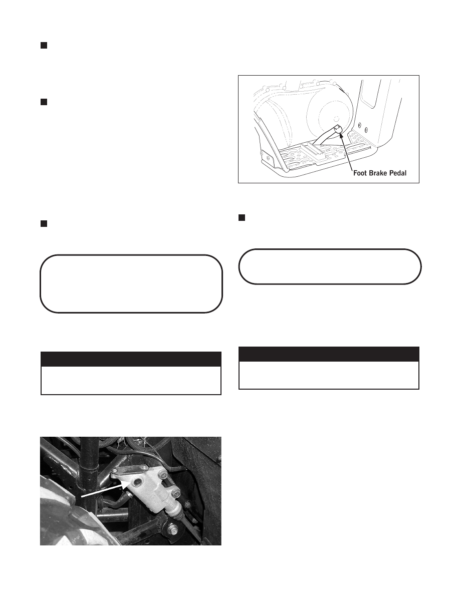
2. Press the foot brake pedal several times to check for

firmness.

Fig. 2-103

0735-507

3. If the pedal is not firm, the system must be held.

NOTE: To bleed the hydraulic foot brake system,

use the basic procedure in Hydraulic Hand Brake
System in this section.

Burnishing Brake Pads

Brake pads (both hydraulic and mechanical) must be
burnished to achieve full braking effectiveness. Braking
distance will be extended until brake pads are properly
burnished. To properly burnish the brake pads, use the
following procedure.

! WARNING

Failure to properly burnish the brake pads could
lead to premature brake pad wear or brake loss.
Brake loss can result in severe injury.

1. Choose an area large enough to safely accelerate the

ATV to 30 mph and to brake to a stop.

2. Using third gear, accelerate to 30 mph; then

compress brake lever or apply the mechanical foot
brake to decelerate to 0-5 mph.

3. Repeat procedure on each brake system 20 times

until brake pads are burnished.

4. Adjust the mechanical brake (if necessary).

5. Verify that the brakelight illuminates when the hand

lever is compressed or the brake pedal is depressed.

2-32

-------------------------------------------------------------------------------------------------------------------------------------------------------------

Coolant

(400/500 cc)

The cooling system capacity is approximately 2.9 L (3
U.S. qt). The cooling system should be inspected daily
for leakage and damage. Also, the coolant level should
be checked periodically.

When filling the cooling system, use premixed Arctic
Cat Antifreeze (p/n 0638-395). While the cooling
system is being filled, air pockets may develop;
therefore, run the engine for five minutes after the initial
fill, shut the engine off, and then fill the cooling system
to 1/2 in. above the radiator core.

Fig. 2-104

AN604D

After operating the ATV for the initial 5-10
minutes, stop the engine, allow the engine to
cool  down, and  check the coolant level. Add
coolant as necessary.

Checking/Replacing

V-Belt

(Automatic Transmission)

REMOVING

1. Remove the three cap screws and nuts securing the

footrest  to the frame; then remove the two cap
screws securing the rear fender to the footrest.

Fig. 2-105

CC790A

2. Swing the rear of the footrest away from the engine;

then remove the two cap screws securing the front
fender to the footrest. Remove the footrest.

Fig. 2-106

CC541

3. Loosen the clamp securing the cooling shroud to

the cooling duct.

! CAUTION

2

2-33

-------------------------------------------------------------------------------------------------------------------------------------------------------------

Fig. 2-107

CC745

4. Remove the cap screws securing the cooling shroud

to the V-belt cover; then remove the cooling shroud.

Fig. 2-108

CC540

NOTE: Note the location of the main engine

ground wire for installing purposes.

Fig. 2-109

CC542A

5. Remove the cotter pin securing the master cylinder

push rod to the brake pedal. Account for the washer.

Fig. 2-110

CC543

6. Remove the brake pedal return spring from the hole

in the frame.

Fig. 2-111

CC556

7. Remove the cap screws securing the V-belt cover

noting the location of the different-lengthed cap
screws for installing purposes; then using a rubber
mallet, gently tap on the cover tabs to loosen the
cover. Remove the cover.

Fig. 2-112

CC540

8. Remove the nut securing the movable drive face;

then remove the face. Account for the spacer.

2-34

-------------------------------------------------------------------------------------------------------------------------------------------------------------

Fig. 2-113

CC546

Fig. 2-114

CC547

9. Remove the V-belt.

Fig. 2-115

CC550

INSTALLING

1. Spread the faces of the driven clutch by pushing the

inner face toward the engine while turning it
counterclockwise; then when the faces are
separated, insert a wedge (approximately 3/8 in.
thick) between the faces. Release the inner face.

Fig. 2-116

CC549

2. Place the V-belt into position on the driven clutch

and over the front shaft.

Fig. 2-117

CC550

NOTE: The arrow on the V-belt should point

forward.

3. Pinch the V-belt together near its center and slide

the spacer and movable drive face onto the clutch
shaft. Secure the drive face with a nut (threads
coated with red Loctite #271). Tighten the nut to
10.4-11.8 kg-m (75-85 ft-lb).

Fig. 2-118

CC552

NOTE: At this point, the wedge can be removed

from between the driven clutch faces.

2

2-35

-------------------------------------------------------------------------------------------------------------------------------------------------------------

4. Rotate the V-belt and clutches until the V-belt is

flush with the top of the driven clutch.

NOTE: Before  proceeding, make  sure the foot

brake pedal return spring is properly positioned as
shown.

Fig. 2-119

CC555A

5. Place the V-belt cover gasket into position; then

install the cover and secure with the cap screws
making sure the different-lengthed cap screws are
in their proper location. Tighten the cap screws to
1.1 kg-m (8 ft-lb).

Fig. 2-120

CC736

NOTE: Make sure the main engine ground wire is

installed and secured in the proper location.

Fig. 2-121

CC542A

6. Place the brake pedal return spring in the hole in the

frame.

Fig. 2-122

CC556

7. Secure the master cylinder push rod to the brake

pedal with a washer and cotter pin.

Fig. 2-123

CC557

8. Place the cooling shroud into position on the V-belt

cover; then secure with cap screws. Tighten to 1.1
kg-m (8 ft-lb).

9. Tighten the clamp securing the cooling shroud to

the cooling duct.

Fig. 2-124

CC745

10. Secure the front fender to the footrest with the two

cap screws. Tighten securely.

2-36

-------------------------------------------------------------------------------------------------------------------------------------------------------------

Fig. 2-125

CC541

11. Slide the footrest into position on the frame; then

secure the rear fender to the footrest with two cap
screws. Tighten securely.

12. Secure the footrest to the frame with three cap

screws and nuts. Tighten cap screws and nuts to 2.8
kg-m (20 ft-lb).

2

2-37

+


Click Here to Continue

-------------------------------------------------------------------------------------------------------------------------------------------------------------

-------------------------------------------------------------------------------------------------------------------------------------------------------------

-------------------------------------------------------------------------------------------------------------------------------------------------------------

Engine/Transmission

This section has been organized into sub-sections which
show a progression for the complete servicing of the
A r c t i c C a t AT V 2 5 0 / 3 0 0 c c a nd 400 /5 00 c c
engine/transmission.

To s e r v i c e t h e c e n t e r c r a n k c a s e h a l ve s , t h e
engine/transmission must be removed from the frame.

To serv ice top-side, left-side, and right-side
components, the engine/transmission does not have to
be removed from the frame.

NOTE: Arctic Cat recommends the use of new

gaskets, lock nuts, and seals and lubricating all
i n t e r n a l c o m po n e n t s w h e n s e r v i c i n g t h e
engine/transmission.

NOTE: Some photographs and illustrations used

in this section are used for clarity purposes only
and are not designed to depict actual conditions.

Specifications*

(250/300 cc)

VALVES AND GUIDES

Valve Face Diameter

(intake)

(exhaust)

33 mm (1.3 in.)
28 mm (1.1 in.)

Valve/Tappet Clearance

(cold engine)

(intake)

(exhaust)
(exhaust)

0.03-0.08 mm (0.001-0.003 in.)
0.08-0.13 mm (0.003-0.005 in.)**
0.17-0.22 mm (0.007-0.009 in.)

Valve Guide/Stem

(intake)

Clearance

(exhaust)

0.010-0.037 mm (0.0004-0.0015 in.)
0.030-0.057 mm (0.0012-0.0024 in.)

Valve Guide/Valve

(max)

Stem Deflection

(wobble method)

0.35 mm (0.014 in.)

Valve Guide Inside Diameter

5.500-5.512 mm (0.2165-0.2170 in.)

Valve Stem Outside

(intake)

Diameter

(exhaust)

5.475-5.490 mm (0.2156-0.2161 in.)
5.455-5.470 mm (0.2148-0.2154 in.)

Valve Stem Runout

(max)

0.05 mm (0.002 in.)

Valve Head Thickness

(max)

0.5 mm (0.02 in.)

Valve Stem End Length

(max)

2.7 mm (0.11 in.)

Valve Face/Seat Width

0.9-1.1 mm (0.035-0.043 in.)

Valve Seat Angle

(intake)

(exhaust)

45°
45°

Valve Face Radial

(max)

Runout

0.03 mm (0.001 in.)

Valve Spring Free

(inner)

Length (max)

(outer)

35.1 mm (1.38 in.)
39.9 mm (1.57 in.)

Valve Spring Tension

(inner)

@ 32.5 mm (1.28 in.)

7.1-9.2 kg (15.7-20.3 lb)

Valve Spring Tension

(outer)

@ 36.0 mm (1.42 in.)

17.3-21.3 kg (38.1-47.0 lb)

CAMSHAFT AND CYLINDER HEAD

Cam Lobe Height (min)

(intake)

(exhaust)

33.820 mm (1.331 in.)
33.490 mm (1.318 in.)

Camshaft Journal Oil

(max)

Clearance

0.15 mm (0.0059 in.)

Camshaft Journal

Holder Inside Diameter

22.012-22.025 mm
(0.8666-0.8671 in.)

Camshaft Journal

Outside Diameter

21.959-21.980 mm
(0.8645-0.8654 in.)

Camshaft Runout

(max)

0.10 mm (0.004 in.)

Rocker Arm Inside Diameter

12.000-12.018 mm (0.472-0.473 in.)

Rocker Arm Shaft Outside

Diameter

11.977-11.995 mm (0.4715-0.4722 in.)

Cylinder Head Distortion (max)

0.05 mm (0.002 in.)

Cylinder Head Cover

(max)

Distortion

0.05 mm (0.002 in.)

CYLINDER, PISTON, AND RINGS

Piston Skirt/Cylinder Clearance (max)

0.12 mm (0.0047 in.)

Cylinder Bore

(max)

68.580 mm

66 mm**

(2.700 in.)

(2.598 in.)**

Piston Diameter

18 mm (0.71 in.)
from Skirt End

68.380 mm
(2.6921 in.)

Piston Ring

(1st Ring)

Free End Gap

(2nd Ring)

6.2-7.8 mm
(0.24-0.31 in.)
7.3-9.1 mm
(0.29-0.36 in.)

Bore x Stroke

68.5 x 76 mm

66 x 72 mm**

(2.69 x 2.99 in.)

(2.60 x 2.84 in.)**

Cylinder Trueness

(max)

0.05 mm (0.002 in.)

Ring End Gap

(1st Ring)

(2nd Ring)

0.70 mm (0.028 in.)
1.0 mm (0.039 in.)

Piston Ring to Groove

(1st)

Clearance (max)

(2nd)

0.180 mm
(0.0071 in.)
0.150 mm
(0.0059 in.)

Piston Ring Groove

(1st)

Width

(2nd)

(oil)

1.01-1.04 mm
(0.040-0.041 in.)
1.22-1.24 mm
(0.048-0.049 in.)
2.01-2.03 mm
(0.079-0.080 in.)

Piston Ring Thickness

(1st)

(2nd)

0.97-0.99 mm
(0.038-0.039 in.)
1.17-1.19 mm
(0.046-0.047 in.)

Piston Pin Bore

(max)

17.030 mm (0.6705 in.)

Piston Pin Outside

(min)

Diameter

16.980 mm (0.6685 in.)

CRANKSHAFT

Connecting Rod

(small end inside diameter)

(max)

17.040 mm (0.6709 in.)

Connecting Rod

(big end side-to-side)

0.1-1.0 mm (0.004-0.039 in.)

Connecting Rod (big end width)

17.95-18.00 mm
(0.707-0.709 in.)

Connecting Rod

Small End Deflection

(max)

3 mm (0.12 in.)

Crankshaft (web-to-web)

55 mm

+ 0.1 mm

(2.165 in.) (+ 0.004 in.)

Crankshaft Runout (max)

(left)

(right)

0.05 mm (0.002 in.)
0.08 mm (0.003 in.)

Oil Pump Reduction Ratio

1.566 (47/30)

Oil Pressure at 60°C

(above)

(140°F) @3000 RPM

(below)

10 psi
40 psi

CLUTCH

Clutch Release Screw

1/8 turn back

Drive Plate (fiber) Thickness

(min)

2.42 mm (0.094 in.)

Drive Plate (fiber) Tab

(min)

11 mm (0.43 in.)

Driven Plate (warpage)

(max)

0.1 mm (0.004 in.)

Clutch Spring Length

(min)

27.5 mm (1.08 in.)

Clutch Wheel

Inside Diameter

(max)

Scuffing of
contact surface

Starter Clutch Shoe

No groove at any part

3-2

-------------------------------------------------------------------------------------------------------------------------------------------------------------

CLUTCH (cont)

Clutch Engagement

RPM

1900 + 200

Clutch Lock-Up

RPM

3400 + 300

Primary Reduction Ratio

3.150 (63/20)

Secondary Reduction Ratio

1.125 (18/16)

Final Reduction Ratio

(front)

(rear)

3.090 (34/11)
3.647 (62/17)

Secondary-

(super low)

Transmission

(low)

Reduction Ratio

(high)

3.176 (17/18 x 25/11 x 37/25)
1.480 (37/25)
1.112 (11/25 x 18/17 x 43/18)

Gear Ratios

(1st)

(2nd)

(3rd)

(4th)
(5th)

(reverse)

3.083 (37/12)
1.933 (29/15)
1.388 (25/18)
1.095 (23/21)
0.913 (21/23)
2.833 (29/12 x 34/29)

Engine Fork To Groove

(side clearance)

0.10-0.50 mm
(0.004-0.020 in.)

Secondary Transmission Fork

to Groove (side clearance)

0.05-0.50 mm
(0.002-0.020 in.)

Reverse Fork to Groove

(side clearance)

0.10-0.50 mm
(0.004-0.020 in.)

Shift Fork Groove

(#1, #2, & #3)

Width

(secondary transmission-

#1 & #2)

(reverse)

4.5-4.6 mm
(0.177-0.181 in.)
5.45-5.55 mm
(0.215-0.219 in.)
4.0-4.1 mm
0.157-0.161 in.)

Shift Fork

(#1, #2, & #3)

Thickness

(secondary transmission-

#1 & #2)

(reverse)

4.3-4.4 mm
(0.169-0.173 in.)
5.3-5.4 mm
(0.209-0.213 in.)
3.8-3.9 mm
(0.150-0.154 in.)

Engine Oil

(off

Þ

on)

Thermo-Switch

(on

Þ

off)

Operating Temperature

160° C (320°F)

N/A**

140° C (284°F)

* Specifications subject to change without notice.
**250 cc

Specifications*

(400/500 cc)

NOTE: Specifications for the clutch components

apply to the manual transmission models only.

VALVES AND GUIDES

Valve Face Diameter

(intake)

(exhaust)

30.6 mm (1.20 in.)
27.0 mm (1.06 in.)

Valve/Tappet Clearance

(cold engine)

(intake)

(exhaust)

0.05-0.10 mm (0.002-0.004 in.)
0.17-0.22 mm (0.007-0.009 in.)

Valve Guide/Stem

(intake)

Clearance

(exhaust)

0.010-0.037 mm
(0.0004-0.0015 in.)
0.030-0.057 mm
(0.0012-0.0022 in.)

Valve Guide/Valve

(max)

Stem Deflection

(wobble method)

0.35 mm (0.014 in.)

Valve Guide Inside Diameter

5.000-5.012 mm (0.1969-0.1973 in.)

Valve Stem Outside

(intake)

Diameter

(exhaust)

4.975-4.990 mm
(0.1959-0.1965 in.)
4.955-4.970 mm
(0.1951-0.1957 in.)

Valve Stem Runout

(max)

0.05 mm (0.002 in.)

Valve Head Thickness

(max)

0.5 mm (0.02 in.)

Valve Stem End Length

(max)

1.8 mm (0.07 in.)

Valve Face/Seat Width

0.9-1.1 mm (0.035-0.043 in.)

VALVES AND GUIDES (cont)

Valve Seat Angle

(intake)

(exhaust)

45°
45°

Valve Face Radial

(max)

Runout

0.03 mm (0.001 in.)

Valve Spring Free

Length (max)

(inner)

(outer)

35.1 mm (1.38 in.)
37.8 mm (1.49 in.)

Valve Spring Tension

(inner)

@ 28 mm (1.10 in.)

5.3-6.5 kg (11.7-14.3 lb)

Valve Spring Tension

(outer)

@ 31.5 mm (1.24 in.)

13.1-15.1 kg (28.9-33.3 lb)

CAMSHAFT AND CYLINDER HEAD

Cam Lobe Height (min)

(intake)

(exhaust)

33.150 mm (1.305 in.)
33.220 mm (1.308 in.)

Camshaft Journal Oil

(max)

Clearance

0.15 mm (0.0059 in.)

Camshaft Journal

(right & center)

Holder Inside

Diameter

(left)

22.012-22.025 mm
(0.8666-0.8671 in.)
17.512-17.525 mm
(0.6894-0.6900 in.)

Camshaft Journal

(right & center)

Outside Diameter

(left)

21.959-21.980 mm
(0.8645-0.8654 in.)
17.465-17.484 mm
(0.6876-0.6883 in.)

Camshaft Runout

(max)

0.10 mm (0.004 in.)

Rocker Arm Inside Diameter

12.000-12.018 mm (0.472-0.473 in.)

Rocker Arm Shaft Outside

Diameter

11.973-11.984 mm (0.4714-0.4718 in.)

Cylinder Head Distortion (max)

0.05 mm (0.002 in.)

Cylinder Head Cover

(max)

Distortion

0.05 mm (0.002 in.)

CYLINDER, PISTON, AND RINGS

Piston Skirt/Cylinder Clearance

0.045-0.120 mm

0.038-0.076 mm**

(0.0018-0.0047 in.)

(0.0015-0.0030 in.)**

Cylinder Bore

84.000-84.085 mm

87.500-87.515 mm**

(3.3071-3.3104 in.)

(3.4448-3.4454 in.)**

Piston Diameter

15 mm (0.60 in.)

from Skirt End

83.880-83.965 mm

87.465-87.470 mm**

(3.3024-3.3057 in.)

(3.4435-3.4437 in.)**

Piston Ring

(1st Ring)

Free End Gap

(2nd Ring)

8.4-10.5 mm (approx)

11.3 mm (max)**

(0.33-0.41 in.) (approx)

(0.4448 in.)**

9.5-11.8 mm (approx)

9.7 mm (max)**

(0.37-0.46 in.) (approx)

(0.3818 in.)**

Bore x Stroke

84 x 67 mm

87.5 x 82 mm**

(3.30 x 2.64 in.)

(3.40 x 3.22 in.)**

Cylinder Trueness

(max)

0.05 mm (0.002 in.)

Ring End Gap

(max)

0.50 mm

0.70 mm**

(0.020 in.)

(0.028 in.)**

Piston Ring to Groove

(1st)

Clearance (max)

(2nd)

0.180 mm
(0.0071 in.)
0.150 mm
(0.0059 in.)

Piston Ring Groove

(1st)

Width

(2nd)

(oil)

1.21-1.23 mm

1.01-1.03 mm**

(0.0476-0.0484 in.)

(0.0397-0.0405 in.)**

1.21-1.23 mm
(0.0476-0.0484 in.)
2.51-2.53 mm
(0.0988-0.0996 in.)

Piston Ring Thickness

(1st)

(2nd)

1.17-1.19 mm

0.97-0.99 mm**

(0.046-0.047 in.)

(0.0382-0.0389 in.)**

1.17-1.19 mm
(0.046-0.047 in.)

Piston Pin Bore

(max)

21.03 mm

23.03 mm**

(0.828 in.)

(0.907 in.)**

Piston Pin Outside

(min)

Diameter

20.98 mm

22.98 mm**

(0.826 in.)

(0.905 in.)**

CRANKSHAFT

Connecting Rod

(small end inside diameter)

(max)

21.04 mm

23.04 mm**

(0.8283 in.)

(0.9070 in.)**

Connecting Rod

(big end side-to-side)

0.1-1.0 mm (0.004-0.039 in.)

Connecting Rod (big end width)

25.95-26.00 mm

24.95-25.00 mm**

(1.022-1.024 in.)

(0.9822-0.9842 in.)**

Connecting Rod

Small End Deflection

(max)

3 mm (0.12 in.)

3

3-3

-------------------------------------------------------------------------------------------------------------------------------------------------------------

CRANKSHAFT (cont)

Crankshaft (web-to-web)

70.9-71.1 mm
(2.796-2.804 in.)

Crankshaft Runout

(max)

0.05 mm

0.08 mm**

(0.002 in.)

(0.003 in.)**

Oil Pump Reduction Ratio

1.45 (29/20)

Oil Pressure at 60°C

(above)

(140°F) @3000 RPM

(below)

1.3 kg/cm² (18 psi)
1.7 kg/cm² (24 psi)

CLUTCH

Clutch Release Screw

1/8 turn back

1/4-1/2 turn back**

Drive Plate (fiber) Thickness

(min)

2.62 mm

2.92-3.08 mm**

(0.103 in.)

(0.1149-0.1212 in.)**

Drive Plate (fiber) Tab

(min)

13-14 mm

13.05 mm**

(0.50-0.55 in.)

(0.5137 in.)**

Driven Plate (warpage)

(max)

0.1 mm (0.004 in.)

Clutch Spring Length

(min)

33.7 mm (1.33 in.)

Clutch Wheel

Inside Diameter

139.8-140.2 mm

140.0-140.2 mm**

(5.504-5.520 in.)

(5.511-5.520 in.)**

Starter Clutch Shoe

No groove at any part

Clutch Engagement

RPM

1700 + 200

Clutch Lock-Up

RPM

3500 + 300

3600 ± 300**

Primary Reduction Ratio

2.392 (67/28)

Secondary Reduction Ratio

1.133 (17/15)

Final Reduction Ratio

(front)

(rear)

3.6 (36/10)
3.6 (36/10)

Secondary-Transmission

(low)

Reduction Ratio

(high)

2.363 (22/23 x 28/17 x 42/28)
1.5 (42/28)

Gear Ratios

(1st)

(2nd)

(3rd)

(4th)
(5th)

(reverse)

3.09 (34/11)
1.75 (28/16)
1.2 (24/20)
0.956 (22/23)
0.8 (20/25)
2.636 (24/11 x 29/24)

Engine Fork To Groove

(side clearance)

0.1-0.3 mm
(0.004-0.012 in.)

Secondary Transmission Fork

(max)

to Groove (side clearance)

0.2 mm
(0.008 in.)

Reverse Fork to Groove

(max)

(side clearance)

0.3 mm

0.2 mm**

(0.012 in.)

(0.008 in.)**

Shift Fork Groove

(#1and #2)

Width

(secondary transmission)

(reverse)

5.5-5.6 mm
(0.217-0.220 in.)
5.4-5.5 mm
(0.213-0.217 in.)
5.0-5.1 mm

4.9-5.0 mm**

0.197-0.201 in.)

(0.193-0.197 in.)**

Shift Fork

(#1 and #2)

Thickness

(secondary transmission)

(reverse)

5.3-5.4 mm
(0.209-0.213 in.)
5.3-5.4 mm
(0.209-0.213 in.)
4.8-4.9 mm
(0.189-0.193 in.)

Thermostat Valve Opening

Temperature

48.5-51.5°C

73.5-76.5°C**

(119.3-124.7°F)

(164-170°F)**

Thermostat Valve Lift

Over 3 mm (0.12 in.)
@ 65°C (149°F

Cooling Fan

(off

Þ

on)

Thermo-Switch

(on

Þ

off)

Operating Temperature

Constant

88-93°C** (190-200°F)**

Constant

81°C** (177°F)** (min)

Table of Contents

(250/300 cc)

Removing Engine/Transmission . . . . . . . .  3-4
Top-Side Components . . . . . . . . . . . . . 3-10
Removing Top-Side Components . . . . . . . 3-10
Left-Side Components . . . . . . . . . . . . . 3-14
Removing Left-Side Components . . . . . . . 3-15
Right-Side Components . . . . . . . . . . . . 3-20
Removing Right-Side Components . . . . . . . 3-21
Center Crankcase Components . . . . . . . . 3-24
Separating Crankcase Halves . . . . . . . . . 3-25
Disassembling Crankcase Half . . . . . . . . . 3-26
Assembling Crankcase Half . . . . . . . . . . 3-29
Joining Crankcase Halves . . . . . . . . . . . 3-33
Installing Right-Side Components . . . . . . . 3-34
Installing Left-Side Components . . . . . . . . 3-40
Installing Top-Side Components . . . . . . . . 3-44
Installing Engine/Transmission . . . . . . . . . 3-51

Removing Engine/

Transmission

Many service procedures can be performed without
removing the engine/transmission from the frame.
Closely observe the note introducing each sub-section
for this important information.

If the technician’s objective is to service/replace
left-side cover oil seals (3), front output joint oil
seal (1), rear output joint oil seal (1), and/or the
o i l s t r a i n e r ( f rom b e ne a t h t he e ng in e /
transmission), the engine/transmission does not
have to be removed from the frame.

1. Lift the seat lock lever and remove the seat.

2. Disconnect the battery by removing the negative

cable first and then the positive cable.

+

AT THIS POINT

* Specifications subject to change without notice.
** 500 cc

3-4

-------------------------------------------------------------------------------------------------------------------------------------------------------------

Fig. 3-1

AF878D

Fig. 3-2

AF880D

3. Remove the battery hold-down bracket; then

remove the battery.

Battery acid is harmful if it contacts eyes, skin,
or clothing. Care must be taken whenever
handling a battery.

4. Drain the oil from the engine/transmission.

NOTE: To drain the oil completely, both the engine

and transmission plugs must be removed.

Fig. 3-3

CC527D

5. Turn the gas tank valve to the OFF position.

6. Remove the springs securing the exhaust header

pipe to the engine.

Fig. 3-4

CH055D

7. Loosen the exhaust pipe from the muffler and the

frame; then remove the exhaust pipe. Account for
grafoil gaskets.

Fig. 3-5

CH056D

8. Mark the position of the hi/low range shifter arm;

then remove the hi/low range shifter arm.

Fig. 3-6

CH057D

! CAUTION

3

3-5

-------------------------------------------------------------------------------------------------------------------------------------------------------------

Fig. 3-7

CH058D

9. Mark the gear shifter arm; then remove the cap

screw securing the gear shifter arm.

Fig. 3-8

CH059D

Fig. 3-9

CH060

10. Mark the reverse gear shaft arm to the reverse shift

shaft to aid in installing; then remove the cap screw
securing the reverse gear shaft arm to the reverse
shift shaft.

Fig. 3-10

CH061D

11. Remove the cap screws securing the air-intake

snorkel to the frame; then loosen the hose clamp at
the air-cleaner assembly.

Fig. 3-11

CH040D

12. Loosen the clamps securing the carburetor boots to

the air intake and the engine.

Fig. 3-12

CH041D

13. Remove the cap screws securing the air-cleaner

assembly from the rear of the ATV.

3-6

-------------------------------------------------------------------------------------------------------------------------------------------------------------

Fig. 3-13

CH047D

14. Remove the cap screws securing the CDI unit.

Fig. 3-14

AF882D

15. Remove the remaining cap screw  securing  the

air-cleaner assembly to the frame; then remove the
crankcase breather hoses from the air-cleaner
assembly and remove the assembly.

Fig. 3-15

CH048D

16. Route the carburetor assembly up and away from

the engine.

NOTE: It will not be necessary to disconnect the

choke cable. Also, use cable ties or tape to secure
the carburetor assembly to keep it from interfering
with the removal procedure.

17. Remove the clips securing the shifter cables to the

bracket.

Fig. 3-16

CH062D

18. Disconnect the positive cable from the starter

motor.

Fig. 3-17

CH063D

19. Disconnect the battery  ground  (negative) cable

from the crankcase cover.

Fig. 3-18

CH064D

20. Disconnect the high tension lead from the spark

plug.

21. Disconnect the main wiring harness connectors.

3

3-7

-------------------------------------------------------------------------------------------------------------------------------------------------------------

Fig. 3-19

CH065D

22. Remove the right-hand side panel.

Fig. 3-20

CH066D

23. Disconnect the oil light switch.

Fig. 3-21

CH067D

24. Remove the rear hydraulic brake caliper.

Fig. 3-22

CH068D

25. Remove the mechanical foot brake.

Fig. 3-23

CH069D

26. Remove the torx-head screw securing the brake

hose to the upper suspension arm.

27. Remove the two oil cooler hoses from the engine.

Fig. 3-24

CH070D

28. Remove the skid plate from the rear end assembly.

29. Remove the two lower cap screws securing the

sub-frame/engine assembly to the frame.

3-8

-------------------------------------------------------------------------------------------------------------------------------------------------------------

Fig. 3-25

CH071D

30. Secure the upper rear of the ATV to the work stand

using tie-down straps to help prevent the ATV from
falling forward when the engine/sub-frame
assembly is removed.

! WARNING

Support the ATV so it doesn’t fall off the work
stand when the engine/sub-frame assembly is
removed from the frame or severe damage,
injury, or death may result.

31. Place a large floor/transmission  jack under the

engine assembly; then remove the upper four cap
screws securing the sub-frame to the frame. Place
the engine assembly on a suitable work stand and
remove the wheels.

Fig. 3-26

CH072D

Fig. 3-27

CH073D

32. Remove the cap screw securing the front engine

mount to the sub-frame. Account for spacers.

Fig. 3-28

CH074D

33. Remove the upper shock mount cap screw to allow

access for removal of the two rear engine mount cap
screws.

Fig. 3-29

CH076D

34. Remove the two rear cap screws securing the

engine to the sub-frame.

3

3-9

-------------------------------------------------------------------------------------------------------------------------------------------------------------


Content      ..     2      3      4      5     ..