ATV Arctic Cat 2002. Service Manual - part 23
8-14
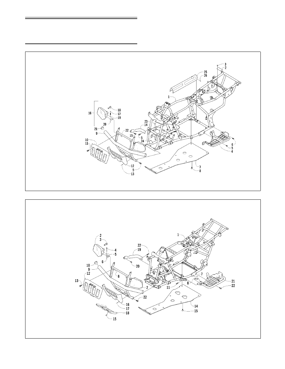
Frame/Exhaust
Assembly Schematics
0737-752
0737-594
KEY
1. Main Frame
2. Bracket
3. Machine Screw
4. Footrest
5. Cap Screw
6. Cap Screw
7. Belly Panel
8. Body Screw
9. Bumper
10. Grille
11. Machine Screw
12. Grille
13. Machine Screw
14. Bumper
15. Cap Screw
16. Headlight Assy
17. Cap Screw
18. Bulb
19. Bracket
20. Nut
21. Bumper Cap
(300 4x4)
22. Nut
23. Cap Screw*
24. Bracket*
25. Driveshaft
Cover*
26. Cap Screw*
250/300
KEY
1. Main Frame
2. Headlight Assy
3. Bulb
4. Cap Screw
5. Bracket
6. Nut
7. Nut
8. Nut
9. Bumper
10. Cap
11. Cap Screw
12. Grille
13. Machine Screw
14. Belly Panel
15. Body Screw
16. Grille
17. Machine Screw
18. Skid Plate
19. Mounting Channel
20. Cap Screw
21. Footrest
22. Cap Screw
400/500 ACT
!
NOTE: Some components may vary from model
to model. The technician should use discretion
and sound judgment.
* 4x4 Models