ATV Arctic Cat 2002. Service Manual - part 22
7-14
REMOVING
1. Secure the ATV on a support stand to elevate the
wheels.
2. Remove the wheels.
!
NOTE: Keep left-side and right-side wheels sepa-
rated for installing them on their proper sides.
AF611D
CLEANING AND INSPECTING
!
NOTE: Whenever a part is worn excessively,
cracked, or damaged in any way, replacement is
necessary.
1. Clean the wheels and hubs with parts-cleaning
solvent.
2. Clean the tires with soap and water.
3. Inspect each wheel for cracks, dents, or bends.
4. Inspect each tire for cuts, wear, missing lugs, and
leaks.
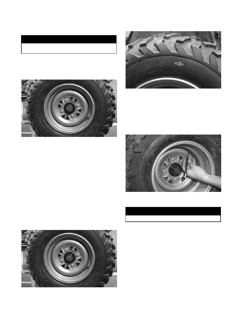
INSTALLING
1. Install each wheel on its hub.
AF611D
!
NOTE: Make sure each wheel is installed on its
proper hub as noted in removing (the “rotation
arrow” must indicate forward direction of rotation).
AF612D
2. Tighten to 5.5 kg-m (40 ft-lb).
CHECKING/INFLATING
1. Using an air pressure gauge, measure the air
pressure in each tire. Adjust the air pressure as
necessary to meet the recommended inflation
pressure.
AL628D
2. Inspect the tires for damage, wear, or punctures.
!
NOTE: If repair is needed, follow the instructions
found on the tire repair kit or remove the wheel
and have it repaired professionally.
!
NOTE: Be sure all tires are the specified size and
have identical tread pattern.
3. Check the front wheel toe-in and toe-out and
adjust as necessary (see Section 8).
4. Test drive the ATV on a dry, level surface and note
any pulling to the left or right during acceleration,
deceleration, and braking.
! WARNING
Make sure the ATV is solidly supported on the sup-
port stand to avoid injury.
! WARNING
Do not operate the ATV if tire damage exists.