ATV Arctic Cat 2002. Service Manual - part 21


  Index      Manuals     ATV Arctic Cat 2002. Service Manual


Search            copyright infringement  


Content      ..     19      20      21      22     ..


ATV Arctic Cat 2002. Service Manual - part 21


6-20

AF637D

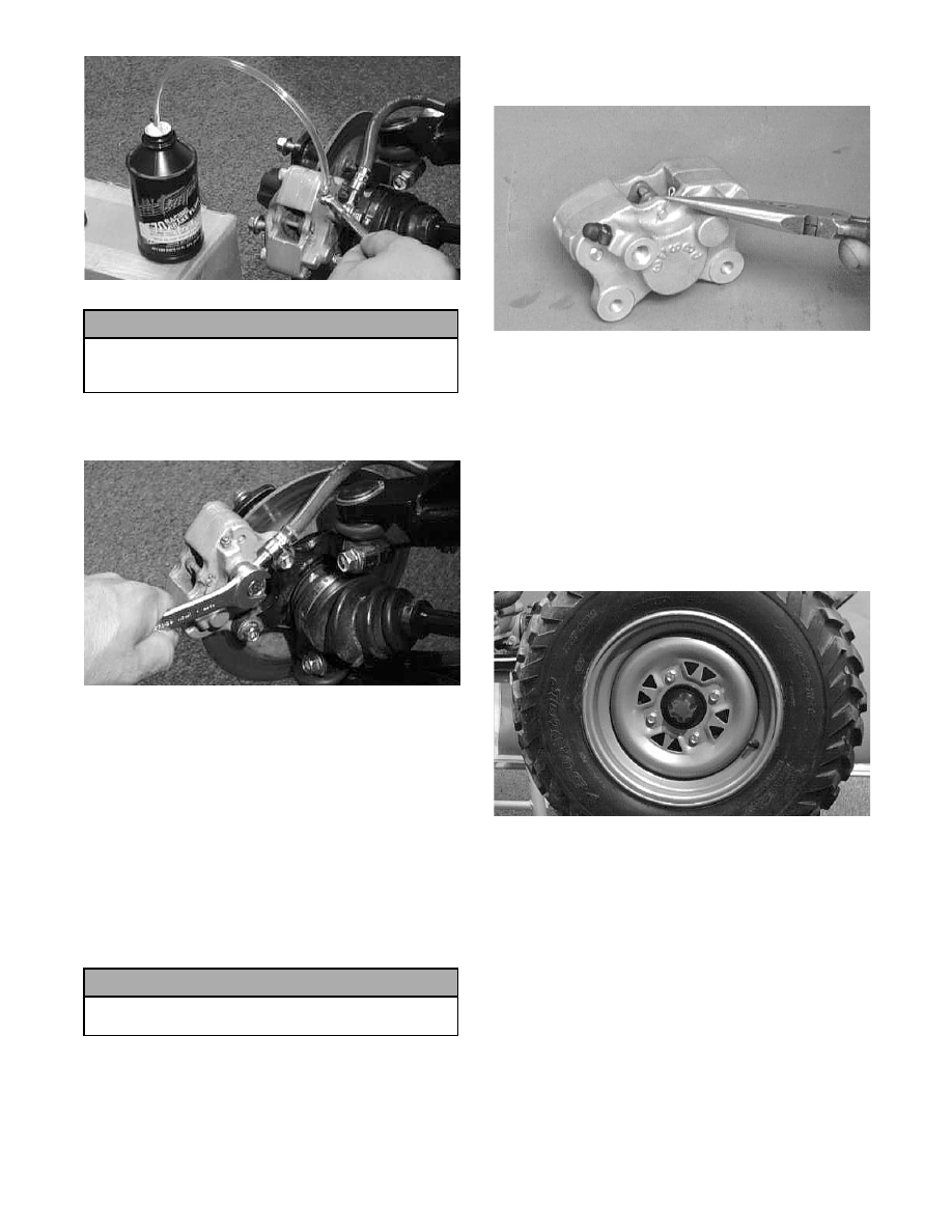
3. Remove the brake hose from the caliper; then

remove the caliper.

AF636D

CLEANING AND INSPECTING

1. Clean all caliper components (except the brake

pads) with parts-cleaning solvent.

2. Inspect the brake pads for damage and excessive

wear.

!

NOTE: For measuring brake pads, see Section 2.

ASSEMBLING/INSTALLING

1. Push the pistons into the caliper as far as they will

go to allow clearance for the brake pads.

2. Install the brake pads and secure with the pin and

cotter pin.

AF718D

3. Place the brake caliper assembly into position and

secure with the cap screws. Tighten the

mechanical caliper to 2.1 kg-m (15 ft-lb). Tighten

the hydraulic caliper to 2.8 kg-m (20 ft-lb).

4. Place a new flat washer on each side of the brake

hose fitting and install it on the caliper. Tighten to

4.2 kg-m (30 ft-lb).

5. Fill the master cylinder; then bleed the brake

system (see Section 2).

6. Install the wheel. Tighten to 5.5 kg-m (40 ft-lb).

AF611D

7. Remove the ATV from the support stand and

verify brake operation.

! CAUTION

Brake fluid is highly corrosive. Do not spill brake
fluid on any surface of the ATV and do not reuse
brake fluid.

! CAUTION

Care should be taken that the piston and cylinder
are not scratched.

RepairPro Service Manual

-------------------------------------------------------------------------------------------------------------------------------------------------------------

6-21

6

Hydraulic Brake 

Assembly Schematics

0735-441

0735-395

KEY

1. Tube - Front
2. Hose - Front
3. Mounting Block
4. Oil Bolt
5. Crush Washer
6. Caliper
7. Housing
8. O-Ring
9. Cotter Pin

10. Pin
11. Bleeder Valve Cap
12. Brake Pad
13. Bleeder Valve
14. O-Ring
15. Socket-Head Screw
16. Hose - Rear
17. Clip
18. Tube - Rear
19. Machine Screw
20. Cap Screw
21. Cap Screw
22. Pressure Switch (4x4)
23. Clamp
24. Machine Screw
25. Nut
26. Housing

250/300

KEY

1. Tube - Front
2. Hose - Front
3. Mounting Block
4. Oil Bolt
5. Crush Washer
6. Caliper
7. Housing
8. O-Ring
9. Cotter Pin

10. Pin
11. Bleeder Valve Cap
12. Brake Pad
13. Bleeder Valve
14. O-Ring
15. Cap Screw
16. Hose - Rear
17. Clip
18. Tube - Rear
19. Cap Screw
20. Cap Screw
21. Cap Screw
22. Pressure Switch
23. Housing

400/500 (Manual Transmission)

-------------------------------------------------------------------------------------------------------------------------------------------------------------

6-22

0735-672

KEY

1. Front Tube
2. Front Hose
3. Mounting Block
4. Oil Bolt
5. Crush Washer
6. Caliper Assy
7. Housing
8. O-Ring
9. Cotter Pin

10. Pin
11. Bleeder Valve Cap
12. Brake Pad
13. Bleeder Valve
14. O-Ring
15. Pressure Switch
16. Cap Screw
17. Rear Hose
18. Clip
19. Rear Tube
20. Cap Screw
21. Cap Screw

375/500 (Automatic Transmission)

RepairPro Service Manual

-------------------------------------------------------------------------------------------------------------------------------------------------------------

-------------------------------------------------------------------------------------------------------------------------------------------------------------

7-2

Front and Rear 

Suspension Assembly 

Schematics

0735-394

0735-825

KEY

1. Retainer
2. Shock Absorber
3. Bushing
4. Sleeve
5. Lock Nut
6. Cap Screw
7. Spring
8. Spring Collar
9. Spring Washer

10. A-Arm
11. Ball Joint
12. Ball Joint Clip
13. Knuckle Assy
14. Knuckle
15. Bearing
16. Bearing Clip
17. Seal
18. Seal
19. Cap Screw
20. Cap Screw
21. A-Arm
22. Drive Axle (4x4)
23. Outer Boot Repair Kit (4x4)
24. Inner Boot Repair Kit (4x4)
25. Retainer
26. Stub Axle (2x4)

250/300 - FRONT

KEY

1. Knuckle Assy
2. Knuckle
3. Collar
4. Bushing
5. Wheel Hub Bearing
6. Bearing Clip
7. Seal
8. Seal
9. Drive Axle

10. Rear Arm
11. A-Arm
12. Shock Absorber
13. Sleeve
14. Bushing
15. Spring Retainer
16. Spring Adjuster Washer
17. Collar
18. Retainer
19. Spring
20. Washer
21. Lock Nut
22. Cap Screw
23. Cap Screw
24. Cap Screw
25. Cap Screw
26. Inner Boot Repair Kit
27. Outer Boot Repair Kit

250/300 - REAR

RepairPro Service Manual

-------------------------------------------------------------------------------------------------------------------------------------------------------------

7-3

7

0735-910

0735-914

KEY

1. Retainer
2. Shock Absorber
3. Bushing
4. Sleeve
5. Lock Nut
6. Cap Screw
7. Spring
8. Spring Collar
9. Spring Washer

10. A-Arm
11. Ball Joint
12. Ball Joint Clip
13. Knuckle Assy
14. Knuckle
15. Wheel Hub Bearing
16. Bearing Clip

 17. Seal

18. Seal
19. Cap Screw
20. Cap Screw
21. A-Arm
22. Drive Axle
23. Outer Boot Repair Kit
24. Inner Boot Repair Kit
25. Retainer
26. Stub Axle (2x4)
27. Boot Guard
28. Body Screw

375/400/500 - FRONT

KEY

1. Cap Screw
2. Cap Screw
3. Swing Arm
4. Lock Nut
5. Spring Adjustment

Washer

6. Swing Arm
7. Retainer
8. Shock Absorber
9. Sleeve

10. Bushing
11. Retainer
12. Cap Screw
13. Spring
14. Collar

ACT - INDEPENDENT REAR SUSPENSION

-------------------------------------------------------------------------------------------------------------------------------------------------------------

7-4

0736-860

Shock Absorbers

REMOVING

1. Secure the ATV on a support stand to elevate the

wheels and to release load on the suspension.

2. Remove the two cap screws and nuts securing

each front shock absorber to the frame. Account

for bushings and sleeves from each.

AF605D

3. Remove the two cap screws and nut securing each

rear shock absorber to the frame and rear

suspension. Account for bushings and sleeves

from each.

AF626D

4. Compress the shock absorber spring, remove the

retainer, and remove the spring.

FULLY INDEPENDENT REAR SUSPENSION

! WARNING

Make sure the ATV is solidly supported on the sup-
port stand to avoid injury.

! CAUTION

On the ACT independent rear suspension,
additional support stands are necessary to
support the rear axle when the shock absorbers
are removed or damage may occur.

RepairPro Service Manual

-------------------------------------------------------------------------------------------------------------------------------------------------------------

7-5

7

AF730D

CLEANING AND INSPECTING

!

NOTE: Whenever a part is worn excessively,

cracked, or damaged in any way, replacement is
necessary.

1. Clean all shock absorber components in

parts-cleaning solvent.

2. Inspect each shock rod for nicks, pits, rust, bends,

and oily residue.

3. Inspect all springs, spring retainers, shock rods,

dampers, bushings, shock bodies, and eyelets for

cracks, leaks, and bends.

INSTALLING

1. Place the shock absorber spring over the shock

absorber, compress the spring, and install the

retainer.

2. Place bushings and sleeves (where appropriate)

into shock eyelet; then install shock with two cap

screws and nuts. Tighten all nuts to 4.8 kg-m (35

ft-lb).

!

NOTE: On the fully independent rear suspension

models, the rear shock absorber-to-lower A-arm
torque factor is 2.8 kg-m  (20 ft-lb).

3. Remove the ATV from the support stand.

Swing Arms 

(ACT - Independent 

Rear Suspension)

REMOVING

1. Remove the cap screws and lock nuts securing the

front of the swing arms to the frame brackets.

2. On the left side, remove the cap screws and lock

nuts securing the rear of the swing arms to the axle

housing; then remove the swing arms.

AF697D

3. On the right side, remove the cap screw and lock

nut securing the outer swing arm to the axle

housing; then remove the cap screw and lock nut

securing the inner swing arm to the axle housing.

Remove the hose grommets from the hose guides.

4. Remove the swing arms and note the location of

the hose guides on the inner swing arm (for

installing purposes).

CLEANING AND INSPECTING

!

NOTE: Whenever a part is worn excessively,

cracked, or damaged in any way, replacement is
necessary.

1. Clean all swing arm components in parts-cleaning

solvent.

2. Inspect all swing arm weldments for cracks or

unusual bends.

3. Inspect all tubing for cracks or unusual bends.

INSTALLING

1. On the right side, place the inner swing arm into

position and secure it to the axle housing with a

cap screw and lock nut. Do not tighten at this time.

2. On the right side, place the outer swing arm into

position and secure to the axle housing with a cap

screw and lock nut. Do not tighten at this time.

! CAUTION

Do not tighten the nuts beyond the 4.8 kg-m (35
ft-lb) specification or the shock eyelet or mount
WILL be damaged.

-------------------------------------------------------------------------------------------------------------------------------------------------------------

7-6

3. Secure the two right side swing arms to the frame

brackets with cap screws and hex nuts. Do not

tighten at this time.

4. On the left side, secure the swing arms to the axle

housing and frame brackets with cap screws and

hex nuts; then tighten all fasteners to 4.8 kg-m (35

ft-lb).

Swing Arms 

(TBX Model)

REMOVING

1. Secure the ATV on a support stand to elevate the

wheels and to release the load on the suspension.

2. Place a floor jack under the rear gear case to

support the gear case once the shock absorber has

been removed.

3. Remove the rear wheels.

4. Remove both brake calipers. Ensure that the

hydraulic brake hose is free from the swing arm.

CC783

!

NOTE: Note the routing of the brake hose for

installing purposes.

5. Remove the three cap screws securing the rear

gear case U-joint to the driveshaft.

6. Remove the cap screw and lock nut securing the

shock assembly to the swing arm. Discard the lock

nut.

!

NOTE: Never reuse a lock nut. Once a lock nut

has been removed, it must be replaced with a new
lock nut.

CC867A

7. Remove the two cap screws and lock nuts securing

the swing arm to the frame. Discard the lock nuts.

CC864

8. Lower the floor jack and remove the swing

arm/rear drive assembly.

9. Remove the four cap screws and lock nuts

securing the swing arm to the axle housing; then

remove the swing arm.

CLEANING AND INSPECTING

!

NOTE: Whenever a part is worn excessively,

cracked, or damaged in any way, replacement is
necessary.

1. Clean all swing arm components in parts-cleaning

solvent.

2. Inspect all swing arm weldments for cracks or

unusual bends.

3. Inspect all tubing for cracks or unusual bends.

INSTALLING

1. Place the swing arm into position on the axle

housing; then secure with cap screws and new lock

nuts. Tighten to 4.8 kg-m (35 ft-lb).   

! WARNING

Make sure the ATV is solidly supported on the sup-
port stand to avoid injury.

! CAUTION

Care should be taken not to damage or kink the
brake cable/hose.

RepairPro Service Manual

-------------------------------------------------------------------------------------------------------------------------------------------------------------

7-7

7

CC867A

2. Place the axle housing/swing arm assembly on a

floor jack and maneuver the assembly into

position in the frame.

3. Secure the swing arm to the frame with cap screws

and new lock nuts. Tighten to 5.5 kg-m (40 ft-lb).

CC864

4. Secure the shock absorber to the swing arm with a

cap screw and new lock nut. Tighten to 4.8 kg-m

(35 ft-lb).

CC868A

5. Secure the rear gear case U-joint to the driveshaft

with three cap screws coated with red Loctite

#271. Tighten to 5.5 kg-m (40 ft-lb).

6. Secure the brake calipers to the bearing housing

with existing hardware. Tighten the mechanical

caliper to 2.1 kg-m (15 ft-lb) and the hydraulic

caliper to 2.8 kg-m (20 ft-lb).

!

NOTE: Ensure that the brake hose is properly

routed and secured on the swing arm as noted
during removing.

CC783

7. Install the wheels and tighten to 5.5 kg-m (40

ft-lb).

8. Remove the ATV from the support stand.

Front A-Arms

REMOVING

1. Secure the ATV on a support stand to elevate the

wheel; then remove the wheel.

2. Remove the wheel cap from the hub; then remove

the cotter pin from the nut.

AF700D

3. Remove the nut securing the hub. Account for a

washer and a hub seal.

! WARNING

Make sure the ATV is solidly supported on the sup-
port stand to avoid injury.

-------------------------------------------------------------------------------------------------------------------------------------------------------------

7-8

AF701D

4. Remove the brake caliper.

AF615D

5. Remove the hub assembly.

6. Remove the cotter pin and slotted nut securing the

tie rod end to the knuckle; then remove the tie rod

end from the knuckle.

AF618D

7. Remove the cap screws securing the ball joints to

the knuckle.

AF628D

8. Tap the ball joints out of the knuckle; then remove

the knuckle.

9. Remove the lower shock absorber eyelet from the

upper A-arm.

AF626D

10. Remove the cap screws securing the A-arms to the

frame.

AF610D

11. Remove the circlip from the ball joint; then

remove the ball joint from the A-arm.

RepairPro Service Manual

-------------------------------------------------------------------------------------------------------------------------------------------------------------

7-9

7

AF616D

CLEANING AND INSPECTING

!

NOTE: Whenever a part is worn excessively,

cracked, or damaged in any way, replacement is
necessary.

1. Clean all A-arm components in parts-cleaning

solvent.

2. Clean the ball joint mounting hole of all residual

Loctite, grease, oil, or dirt for installing purposes.

3. Inspect the A-arm for bends, cracks, and worn

bushings.

4. Inspect the ball joint mounting holes for cracks or

damage.

5. Inspect the frame mounts for signs of damage,

wear, or weldment damage.

INSTALLING

1. Apply green Loctite #609 to the entire outside

diameter of the ball joint; then install the ball joint

into the A-arm and secure with the circlip.

AF616D

2. Install the A-arm assemblies into the frame

mounts and secure with the cap screws. Only

finger-tighten at this time.

AF610D

3. Route the brake hose through the upper A-arm

shock absorber mount.

AF627D

4. Secure the lower eyelet of the shock absorber to

the upper A-arm. Tighten nut to 4.8 kg-m (35

ft-lb).

5. Secure the A-arm assemblies to the frame mounts

(from step 2). Tighten the cap screws to 4.8 kg-m

(35 ft-lb).

6. Install the knuckle assembly onto the ball joints

and secure with cap screws. Tighten to 4.8 kg-m

(35 ft-lb).

AF628D

! CAUTION

Do not tighten the nut beyond the 4.8 kg-m (35
ft-lb) specification or the shock eyelet or mount
WILL be damaged.

-------------------------------------------------------------------------------------------------------------------------------------------------------------

7-10

7. Install the tie rod end and secure with the nut.

Tighten to 4.2 kg-m (30 ft-lb); then install a new

cotter pin and spread the pin to secure the nut.

!

NOTE: During assembly, new cotter pins should

be installed.

AF618D

8. Apply grease to hub sealing area and on the drive

axle splines; then install the hub assembly onto the

drive axle.

AF702D

9. Insert the hub seal onto the drive axle; then

position it into the hub.

AF701D

10. Place the washer onto the shaft; then secure the

hub assembly with the nut. Tighten only until

snug.

11. Secure the brake caliper to the knuckle with the

two cap screws. Tighten to 2.8 kg-m (20 ft-lb).

AF615D

12. Secure the hub nut (from step 10) to the shaft/axle.

Tighten to 10.4 kg-m (75 ft-lb).

13. Install a new cotter pin and spread the pin to

secure the nut.

AF700D

14. Install the wheel cap.

15. Install the wheel and tighten to 5.5 kg-m (40 ft-lb).

AF611D

16. Remove the ATV from the support stand.

RepairPro Service Manual

-------------------------------------------------------------------------------------------------------------------------------------------------------------

7-11

7

Rear A-Arms

(Fully Independent Rear 

Suspension)

REMOVING

1. Secure the ATV on a support stand to elevate the

wheels

.

2. Pump up the hand brake; then engage the brake

lever lock.

3. Remove the wheel and rubber wheel cap.

4. Remove the cotter pin securing the hex nut; then

remove the hex nut and washer. Release the brake

lever lock.

AF700D

5. Remove the two brake calipers (right side only).

!

NOTE: Do not allow the brake calipers to hang

from their cable/hose.

6. Remove the cap screws and lock nut securing the

shock absorber to the frame and lower A-arm; then

remove the shock absorber.

7. Remove the cap screws securing the boot guard to

the lower A-arm.

AF934

8. Slide the hub out of the knuckle and set aside.

9. Remove the cap screws and lock nuts securing the

knuckle to the A-arms. Discard the lock nuts.

AF936

!

NOTE: Never reuse a lock nut. Once a lock nut

has been removed, it must be replaced with a new
lock nut.

10. Remove the cap screws and lock nuts securing the

A-arms to the frame; then remove the A-arms.

!

NOTE: If removing the upper right A-arm, it will

be necessary to disconnect the brake hose and
brake cable from the A-arm.

CLEANING AND INSPECTING

!

NOTE: Whenever a part is worn excessively,

cracked, or damaged in any way, replacement is
necessary.

1. Clean all A-arm components in parts-cleaning

solvent.

2. Inspect the A-arm for bends, cracks, and worn

bushings.

3. Inspect the frame mounts for signs of damage,

wear, or weldment damage.

! WARNING

Make sure the ATV is solidly supported on the sup-
port stand to avoid injury.

-------------------------------------------------------------------------------------------------------------------------------------------------------------

7-12

INSTALLING

1. Install the A-arm assemblies into the frame

mounts and secure with the cap screws and new

lock nuts. Only finger-tighten at this time.

2. Slide the knuckle onto the drive axle and into

position on the A-arms; then secure the knuckle to

the A-arms with cap screws and new lock nuts.

Tighten to 4.8 kg-m (35 ft-lb).

3. Tighten the hardware securing the A-arms to the

frame mounts (from step 1) to 4.8 kg-m (35 ft-lb).

4. Apply grease to hub sealing area and on the drive

axle splines; then install the hub assembly onto the

drive axle.

AF702D

5. Insert the hub seal onto the shaft; then position it

into the hub.

AF701D

6. Place the washer onto the drive axle; then secure

the hub assembly with the nut. Tighten only until

snug.

7. Secure the brake caliper to the knuckle with the

two cap screws (right side only). Tighten the

mechanical caliper to 2.1 kg-m (15 ft-lb). Tighten

the hydraulic caliper to 2.8 kg-m (20 ft-lb).

!

NOTE: Ensure that the brake hose and brake

cable are properly routed and secured to the upper
A-arm.

AF615D

8. Secure the hub nut (from step 6) to the drive axle.

Tighten to 10.4  kg-m (75 ft-lb).

9. Install a new cotter pin and spread the pin to

secure the nut.

AF700D

10. Secure the shock absorber to the frame with a cap

screw and new lock nut. Tighten to 4.8  kg-m (35

ft-lb).

11. Secure the shock absorber to the lower A-arm with

a cap screw and new lock nut. Tighten to 2.8  kg-m

(20 ft-lb).

12. Secure the boot guard to the lower A-arm with the

two cap screws. Tighten securely.

13. Install the wheel cap.

14. Install the wheel and tighten to 5.5  kg-m (40

ft-lb).

15. Remove the ATV from the support stand.

RepairPro Service Manual

-------------------------------------------------------------------------------------------------------------------------------------------------------------

7-13

7

Wheels and Tires

0735-522

TIRE SIZE

The ATV is equipped with low-pressure tubeless tires

of the size and type listed below. Do not under any cir-

cumstances substitute tires of a different type or size.

TIRE INFLATION PRESSURE

On 250/300 models, front and rear tire inflation pres-

sure should be 0.35 kg/cm² (5.0 psi).

On 375/400/500 models, front tire pressure should be

0.32 kg-cm² (4.5 psi) and the rear tire pressure should

be 0.25 kg-cm² (3.5 psi).

KEY

1. Hex Nut
2. Valve Stem Cap
3. Valve Stem
4. Wheel - Front
5. Tire - Front
6. Cotter Pin
7. Washer
8. Hub Seal
9. Wheel Hub - Front

10. Brake Disc
11. Machine Screw
12. Wheel - Rear
13. Tire - Rear
14. Wheel Cap
15. Mounting Nut

! WARNING

Use only Arctic Cat approved tires when replacing
tires. Failure to do so could result in unstable ATV
operation.

250

Front

Rear

Size

AT23 x 8-12

AT24 x 9-12

300

Front

Rear

Size (4x4)

AT24 x 9-12

AT25 x 10-12

Size (2x4)

AT23 x 8-12

AT25 x 10-12

375/400/500

Front

Rear

Size

AT25 x 8-12

AT25 x 10-12

! WARNING

Do not mix tire tread patterns. Use the same pattern
type on front and rear. Failure to heed warning
could cause poor handling qualities of the ATV and
could cause excessive drive train damage not cov-
ered by warranty.

! WARNING

Always maintain proper tire inflation pressure.

-------------------------------------------------------------------------------------------------------------------------------------------------------------


Content      ..     19      20      21      22     ..