ATV Honda TRX350 TM/TE, TRX350 FM/FE. Service Manual - part 67
INSPECTION
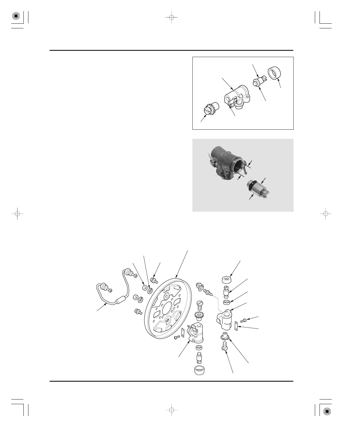
ASSEMBLY
BRAKE SYSTEM
14-12
SERVICE LIMIT:
SERVICE LIMIT:
Measure the piston O.D.
Clean all parts with brake fluid excluding the boots.
Blow out passages with compressed air.
17.515 mm (0.6896 in)
17.405 mm (0.6852 in)
Check the piston cup and boot for wear,
deterioration or damage.
Check the cylinder bore and piston for scoring,
scratches of damage.
Check the adjuster for wear or damage.
Check the lock spring for fatigue or damage.
Measure the wheel cylinder I.D.
OIL PIPE
BOLT
BRAKE PANEL
BOOT
PISTON
CUP
SCREW
LOCK SPRING
CYLINDER B
ADJUSTER SCREW
ADJUSTER NUT
PISTON
CYLINDER
BOOT
CUP
LOCK SPRING
ADJUSTER
WASHER
NUT
CYLINDER A
03/01/08 12:42:20 61HN400H_023