ATV Honda TRX350 TM/TE, TRX350 FM/FE. Service Manual - part 65


  Index      Manuals     ATV Honda TRX350 TM/TE, TRX350 FM/FE. Service Manual


Search            copyright infringement  


Content      ..     63      64      65      66     ..


ATV Honda TRX350 TM/TE, TRX350 FM/FE. Service Manual - part 65


REMOVAL

INSPECTION

FRONT WHEEL/SUSPENSION/STEERING

12-16

TORQUE:

SUSPENSION ARM

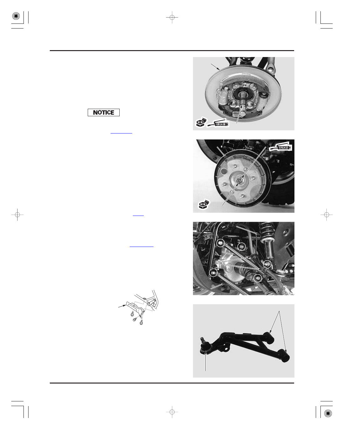
Install the brake panel onto the knuckle and tighten
the four bolts.

Coat a new O-ring with grease and install it into the
axle groove.

Install a new cotter pin.

Install the wheel (page 12-8).

Apply molybdenum disulfide grease to the drive
shaft spline.

Apply grease to the hub nut threads and seating
surface.
Install the brake drum/hub with the hub nut.
Tighten the nut to the specified torque and further
tighten until its grooves align with the cotter pin
hole.

78 N·m (8.0 kgf·m , 58 lbf·ft)

Remove the knuckle (page 12-11).

Remove the following:

Make sure that the waterproof seal on the brake
drum is packed with the multi-purpose grease
(NLGI

3) (page 14-9).

lower arm guard if necessary (FM/FE models)
pivot nuts, bolts and lower arm
two clamp bolts from upper arm
shock absorber lower mounting nut and bolt
pivot nuts, bolts (remove front side first) and
upper arm

Check the pivot bushings for wear or damage.
Inspect the ball joint boot for tears or other damage
by moving the ball joint studs.
It should move freely and smoothly.

B

B

R

R

A

A

K

K

E

E

P

P

A

A

N

N

E

E

L

L

J

J

O

O

I

I

N

N

T

T

B

B

O

O

O

O

T

T

L

L

O

O

W

W

E

E

R

R

A

A

R

R

M

M

C

C

L

L

A

A

M

M

P

P

S

S

S

S

H

H

O

O

C

C

K

K

A

A

B

B

S

S

O

O

R

R

B

B

E

E

R

R

B

B

R

R

A

A

K

K

E

E

D

D

R

R

U

U

M

M

/

/

H

H

U

U

B

B

N

N

U

U

T

T

O

O

-

-

R

R

I

I

N

N

G

G

C

C

O

O

T

T

T

T

E

E

R

R

P

P

I

I

N

N

U

U

P

P

P

P

E

E

R

R

A

A

R

R

M

M

B

B

U

U

S

S

H

H

I

I

N

N

G

G

S

S

LOWER ARM
GUARD

T M/ T E model

only:

F M/ F E model

only:

Do not get grease

onto the brake

drum and shoes.

03/01/08 10:27:14 61HN400G_017

-------------------------------------------------------------------------------------------------------------------------------------------------------------

×

BALL JOINT REPLACEMENT

FRONT WHEEL/SUSPENSION/STEERING

UPPER ARM

KNUCKLE

TOOLS:
Ball joint remover/installer
Attachment, 28

30 mm

TOOLS:
Ball joint remover/installer
Attachment, 20 mm I.D.

12-17

Remove the snap ring from the ball joint.

Set the upper arm and special tools with ‘‘A’’ mark
side of the remover/installer facing to the ball joint
as shown.
Press the ball joint out of the upper arm.

07WMF-HN00100
07946-1870100

Set the upper arm and special tools with ‘‘B’’ mark
side of the remover/installer facing to the ball joint
as shown.
Press the ball joint into the upper arm until it is fully
seated.

If you feel strong resistance when lowering the
press, stop. Reset the attachment of the tool so that
the ball joint head can go into the hollow of the
attachment and try again.

Install the snap ring with the chamfered edge
facing in.

Remove the snap ring and the inner dust seal (FM/
FE model only).

07WMF-HN00100
07746-0020400

S

S

N

N

A

A

P

P

R

R

I

I

N

N

G

G

A

A

B

B

R

R

E

E

M

M

O

O

V

V

E

E

R

R

/

/

I

I

N

N

S

S

T

T

A

A

L

L

L

L

E

E

R

R

A

A

T

T

T

T

A

A

C

C

H

H

M

M

E

E

N

N

T

T

A

A

T

T

T

T

A

A

C

C

H

H

M

M

E

E

N

N

T

T

R

R

E

E

M

M

O

O

V

V

E

E

R

R

/

/

I

I

N

N

S

S

T

T

A

A

L

L

L

L

E

E

R

R

I

I

N

N

N

N

E

E

R

R

D

D

U

U

S

S

T

T

S

S

E

E

A

A

L

L

S

S

N

N

A

A

P

P

R

R

I

I

N

N

G

G

03/01/08 10:27:30 61HN400G_018

-------------------------------------------------------------------------------------------------------------------------------------------------------------


×

INSTALLATION

FRONT WHEEL/SUSPENSION/STEERING

TOOLS:
Ball joint remover/installer
Attachment, 28

30 mm

TOOLS:
Ball joint remover/installer
Attachment, 15 mm I.D.

TORQUE:

Upper/Lower arm:
Shock absorber:

12-18

Set the knuckle and special tools with ‘‘A’’ mark
side of the remover/installer facing to the ball joint,
in a vise as shown.
Press the ball joint out of the knuckle.

07JMF-HC50110
07946-1870100

Install the following:

upper arm onto frame and shock absorber with
pivot bolts (from front side)
new pivot nuts

lower arm with pivot bolts (from front side)
new pivot nuts

Install the brake hose and breather tube onto the
upper arm and tighten the two clamp bolts.

Install the knuckle (page 12-15).

44 N·m (4.5 kgf·m , 33 lbf·ft)

30 N·m (3.1 kgf·m , 22 lbf·ft)

Set the knuckle and special tools with ‘‘B’’ mark
side of the remover/installer facing to the ball joint
in a vise as shown.
Press the ball joint into the knuckle until it is fully
seated.

07JMF-HC50110
07746-0020200

If you feel strong resistance when lowering the
press, stop. Reset the attachment of the tool so that
the ball joint head can go into the hollow of the
attachment and try again.

Install the snap ring with the chamfered edge
facing in.
Install the dust seal (page 12-15).

R

R

E

E

M

M

O

O

V

V

E

E

R

R

/

/

I

I

N

N

S

S

T

T

A

A

L

L

L

L

E

E

R

R

R

R

E

E

M

M

O

O

V

V

E

E

R

R

/

/

I

I

N

N

S

S

T

T

A

A

L

L

L

L

E

E

R

R

A

A

B

B

O

O

L

L

T

T

S

S

A

A

N

N

D

D

N

N

U

U

T

T

S

S

U

U

P

P

P

P

E

E

R

R

A

A

R

R

M

M

B

B

A

A

T

T

T

T

A

A

C

C

H

H

M

M

E

E

N

N

T

T

A

A

T

T

T

T

A

A

C

C

H

H

M

M

E

E

N

N

T

T

B

B

O

O

L

L

T

T

S

S

A

A

N

N

D

D

N

N

U

U

T

T

S

S

C

C

L

L

A

A

M

M

P

P

S

S

H

H

O

O

S

S

E

E

A

A

N

N

D

D

T

T

U

U

B

B

E

E

L

L

O

O

W

W

E

E

R

R

A

A

R

R

M

M

03/01/08 10:27:45 61HN400G_019

-------------------------------------------------------------------------------------------------------------------------------------------------------------


REMOVAL

FRONT WHEEL/SUSPENSION/STEERING

12-19

STEERING SHAFT AND TIE-ROD

Remove the following:

Remove the following:

front fender (page 2-7)
inner fenders (page 2-9)
handlebar cover (U.S.A. TM/FM models)/meter
cover and combination meter (Except U.S.A. TM/
FM) (page 12-3)

wire harness from harness clip (by releasing clip)
cables from guide
brake hose from clamps

lower holder nuts and washers
handlebar assembly from steering shaft

holder bolts
steering shaft holders

cotter pins (from knuckle and steering shaft ball
joint studs)
joint nuts (by holding joint stud flat surfaces)
tie-rods (from steering shaft and knuckles)

N

N

U

U

T

T

S

S

C

C

L

L

I

I

P

P

C

C

L

L

A

A

M

M

P

P

S

S

G

G

U

U

I

I

D

D

E

E

H

H

A

A

N

N

D

D

L

L

E

E

B

B

A

A

R

R

N

N

U

U

T

T

S

S

A

A

N

N

D

D

W

W

A

A

S

S

H

H

E

E

R

R

S

S

H

H

O

O

L

L

D

D

E

E

R

R

S

S

C

C

O

O

T

T

T

T

E

E

R

R

P

P

I

I

N

N

S

S

T

T

I

I

E

E

-

-

R

R

O

O

D

D

B

B

O

O

L

L

T

T

S

S

W hen removing

the tie-rod only, it

can be removed

without removing

the f ront f ender.

Do not twist or

bend the brake

hose and pipe.

03/01/08 10:27:57 61HN400G_020

-------------------------------------------------------------------------------------------------------------------------------------------------------------


INSPECTION

FRONT WHEEL/SUSPENSION/STEERING

12-20

cotter pin (from steering shaft end)
shaft end nut and washer
shaft arm
steering shaft

Inspect the tie-rod for distortion or damage.
Inspect the ball joint boots for tears or other
damage by moving the ball joint studs.
They should move freely and smoothly.

Check the steering shaft bushing for wear or
damage.

Check the steering shaft for distortion or damage.

S

S

T

T

E

E

E

E

R

R

I

I

N

N

G

G

S

S

H

H

A

A

F

F

T

T

C

C

O

O

T

T

T

T

E

E

R

R

P

P

I

I

N

N

N

N

U

U

T

T

A

A

N

N

D

D

W

W

A

A

S

S

H

H

E

E

R

R

A

A

R

R

M

M

03/01/08 10:28:06 61HN400G_021

-------------------------------------------------------------------------------------------------------------------------------------------------------------

×

×

BEARING REPLACEMENT

TIE-ROD ASSEMBLY

FRONT WHEEL/SUSPENSION/STEERING

TOOLS:
Driver
Attachment, 32

35 mm

TOOLS:
Driver
Attachment, 42

47 mm

Pilot, 20 mm

12-21

Turn the inner race of the bearing with your finger.
The bearing should turn smoothly and quietly. Also
check that the bearing outer race fits tightly in the
frame.

Remove the upper and lower dust seals.
Remove the snap ring.

Drive the steering shaft bearing out of the frame
from below.

07749-0010000
07746-0010100

Drive in a new bearing squarely with the marked
side facing up until it is fully seated.

07949-3710001
07746-0010300
07746-0040500

Install the snap ring into the groove properly with
the chamfered edge facing up.

Coat new dust seals with grease and install them
(the upper seal is flush with the frame edge and the
lower seal is fully seated onto the bearing).

When the tie-rod ball joints will be replaced, install
the ball joints and lock nuts as shown.

Adjust the tie-rod length so that the distance
between each lock nut and thread end is 4.5 mm
(TM/TE models)/8.75 mm (FM/FE models). (A
difference between both ends distances is 3 mm
max.)

Temporarily tighten the lock nuts while the ball
joint positions are 180° from each other.

S

S

N

N

A

A

P

P

R

R

I

I

N

N

G

G

D

D

U

U

S

S

T

T

S

S

E

E

A

A

L

L

S

S

B

B

E

E

A

A

R

R

I

I

N

N

G

G

G

G

o

o

l

l

d

d

S

S

i

i

l

l

v

v

e

e

r

r

(

(

l

l

e

e

f

f

t

t

h

h

a

a

n

n

d

d

t

t

h

h

r

r

e

e

a

a

d

d

s

s

)

)

F

F

L

L

A

A

T

T

(

(

w

w

r

r

e

e

n

n

c

c

h

h

h

h

o

o

l

l

d

d

i

i

n

n

g

g

p

p

o

o

s

s

i

i

t

t

i

i

o

o

n

n

)

)

T

T

M

M

/

/

T

T

E

E

:

:

4

4

.

.

5

5

m

m

m

m

(

(

0

0

.

.

2

2

i

i

n

n

)

)

F

F

M

M

/

/

F

F

E

E

:

:

8

8

.

.

7

7

5

5

m

m

m

m

(

(

0

0

.

.

3

3

i

i

n

n

)

)

4

4

.

.

5

5

m

m

m

m

(

(

0

0

.

.

2

2

i

i

n

n

)

)

8

8

.

.

7

7

5

5

m

m

m

m

(

(

0

0

.

.

3

3

i

i

n

n

)

)

T ighten these nuts

af ter installing the

tie-rod into the

knuckle and

steering shaf t.

03/01/08 10:28:20 61HN400G_022

-------------------------------------------------------------------------------------------------------------------------------------------------------------

INSTALLATION

FRONT WHEEL/SUSPENSION/STEERING

12-22

TORQUE:

TORQUE:

TORQUE:

32 N·m (3.3 kgf·m , 24 lbf·ft)

54 N·m (5.5 kgf·m , 40 lbf·ft)

Install the bushing ring onto the shaft bushing.
Apply grease to the shaft bushing inner surface.

Install the shaft bushing onto the steering shaft
with the ‘‘UP’’ mark facing up.
Install the steering shaft into the shaft bearing.

Install the shaft holders and bolts with the hose
clamp on the front holder facing the right side.
Tighten the holder bolts.

Apply grease to the end nut threads and seating
surface.
Apply molybdenum disulfide grease to the steering
shaft spline.

Install the shaft arm over the steering shaft by
aligning the wide tooth with the wide groove.
Install the washer and end nut, and tighten the nut
to the specified torque.

108 N·m (11.0 kgf·m , 80 lbf·ft)

Install a new cotter pin.

Install the tie-rod into the steering shaft and knuckle
with the flat area (wrench holding point) toward the
knuckle.
Install new joint nuts and tighten them by holding
the joint stud flat surfaces.

J

J

O

O

I

I

N

N

T

T

N

N

U

U

T

T

S

S

U

U

P

P

M

M

A

A

R

R

K

K

B

B

U

U

S

S

H

H

I

I

N

N

G

G

C

C

L

L

A

A

M

M

P

P

H

H

O

O

L

L

D

D

E

E

R

R

S

S

B

B

O

O

L

L

T

T

S

S

W

W

A

A

S

S

H

H

E

E

R

R

A

A

N

N

D

D

N

N

U

U

T

T

A

A

R

R

M

M

A

A

l

l

i

i

g

g

n

n

C

C

O

O

T

T

T

T

E

E

R

R

P

P

I

I

N

N

F

F

L

L

A

A

T

T

T

T

I

I

E

E

-

-

R

R

O

O

D

D

J

J

O

O

I

I

N

N

T

T

N

N

U

U

T

T

R

R

I

I

N

N

G

G

S

S

T

T

E

E

E

E

R

R

I

I

N

N

G

G

S

S

H

H

A

A

F

F

T

T

03/01/08 10:28:35 61HN400G_023

-------------------------------------------------------------------------------------------------------------------------------------------------------------


REMOVAL

FRONT WHEEL/SUSPENSION/STEERING

12-23

FRONT SHOCK ABSORBER

TORQUE:

TORQUE:

Install new cotter pins into the ball joint studs.

Install the handlebar assembly onto the steering
shaft with new lower holder nuts and washers.
Tighten the nuts.

Support the vehicle with a support block to raise
the front wheels off the ground.

Support the suspension arm or front wheel, and
remove the mounting nuts, bolts and shock
absorber.

39 N·m (4.0 kgf·m , 29 lbf·ft)

54 N·m (5.5 kgf·m , 40 lbf·ft)

If the tie-rod ball joints were replaced, tighten the
lock nuts as follows:
Rotate both ball joints with the tie-rod axis until
they stop against the ball joint studs. Hold them in
that position and tighten the ball joint lock nuts.

Install the brake hose into the clamps to secure it.
Install the cables into the cable guide.
Secure the wires with the clip.

Adjust the toe (page 3-19).

Install the following:

inner fenders (page 2-9)
front fender (page 2-7)
handlebar cover (U.S.A. TM/FM models)/meter
cover and combination meter (Except U.S.A. TM/
FM) (page 12-3)

C

C

L

L

A

A

M

M

P

P

S

S

C

C

O

O

T

T

T

T

E

E

R

R

P

P

I

I

N

N

C

C

O

O

T

T

T

T

E

E

R

R

P

P

I

I

N

N

S

S

G

G

U

U

I

I

D

D

E

E

C

C

L

L

I

I

P

P

W

W

A

A

S

S

H

H

E

E

R

R

S

S

A

A

N

N

D

D

N

N

U

U

T

T

S

S

S

S

H

H

O

O

C

C

K

K

A

A

B

B

S

S

O

O

R

R

B

B

E

E

R

R

L

L

O

O

C

C

K

K

N

N

U

U

T

T

S

S

H

H

A

A

N

N

D

D

L

L

E

E

B

B

A

A

R

R

Do not twist or

bend the brake

hose and pipe.

Route the wire and

cable properly

( page 1-22).

03/01/08 10:28:47 61HN400G_024

-------------------------------------------------------------------------------------------------------------------------------------------------------------

INSPECTION

INSTALLATION

FRONT WHEEL/SUSPENSION/STEERING

12-24

TORQUE: Upper/Lower:

Apply molybdenum disulfide paste to the lower
bushing of the shock absorber.
Coat new dust seal lips with molybdenum disulfide
paste and install them into the lower pivot until
they are fully seated.
Install the lower pivot collar.

Install the shock absorber with the mounting bolts
from front side.
Install new mounting nuts and tighten them.

30 N·m (3.1 kgf·m , 22 lbf·ft)

Remove the lower pivot collar and dust seals.
Check the pivot collar for wear or damage.

Check the bushings for wear or damage.
Check the damper unit for leakage or other damage.
Replace the shock absorber assembly if necessary.

S

S

H

H

O

O

C

C

K

K

A

A

B

B

S

S

O

O

R

R

B

B

E

E

R

R

C

C

O

O

L

L

L

L

A

A

R

R

D

D

U

U

S

S

T

T

S

S

E

E

A

A

L

L

B

B

O

O

L

L

T

T

S

S

A

A

N

N

D

D

N

N

U

U

T

T

S

S

03/01/08 10:28:55 61HN400G_025

-------------------------------------------------------------------------------------------------------------------------------------------------------------

MEMO

03/01/08 10:28:57 61HN400G_026

-------------------------------------------------------------------------------------------------------------------------------------------------------------

REAR WHEEL/SUSPENSION

13-0

44 N·m (4.5 kgf·m , 33 lbf·ft)

118 N·m (12.0 kgf·m , 87 lbf·ft)

44 N·m (4.5 kgf·m , 33 lbf·ft)

44 N·m (4.5 kgf·m , 33 lbf·ft)

118 N·m (12.0 kgf·m , 87 lbf·ft)

4 N·m (0.4 kgf·m , 2.9 lbf·ft)

03/01/08 12:37:55 61HN400H_001

-------------------------------------------------------------------------------------------------------------------------------------------------------------

SERVICE INFORMATION

13-1

TROUBLESHOOTING

13-2

REAR WHEEL

13-3

REAR SHOCK ABSORBER

13-3

SWINGARM

13-4

SERVICE INFORMATION

13

GENERAL

SPECIFICATIONS

TORQUE VALUES

TM/TE model

FM/FE model

STANDARD

SERVICE LIMIT

ITEM

ITEM

STANDARD

SERVICE LIMIT

13. REAR WHEEL/SUSPENSION

13-1

This section covers service of the rear wheel, rear shock absorber and swingarm.
For tire information, refer to section 12.
For brake system service, refer to section 14.
For rear driving mechanism service, refer to section 16.
A jack or other support is required to support the vehicle.
Use genuine Honda replacement bolts and nuts for all suspension pivots and mounting points.
When using the lock nut wrench, use a deflecting beam type torque wrench 20 inches long. The lock nut wrench
increases the torque wrench’s leverage, so the torque wrench reading will be less than the torque actually applied to the
lock nut. The specification given is the actual torque applied to the lock nut, not the reading on the torque wrench. Do not
overtighten the lock nut. The specification later in the text gives both actual and indicated.

Minimum tire tread depth
Cold tire pressure

Standard
Minimum
Maximum
With cargo

Minimum tire tread depth
Cold tire pressure

Standard
Minimum
Maximum
With cargo

4.0 mm (0.16 in)

4.0 mm (0.16 in)

20 kPa (0.20 kgf/cm , 2.9 psi)
17 kPa (0.17 kgf/cm , 2.5 psi)
23 kPa (0.23 kgf/cm , 3.3 psi)
20 kPa (0.20 kgf/cm , 2.9 psi)

25 kPa (0.25 kgf/cm , 3.6 psi)
22 kPa (0.22 kgf/cm , 3.2 psi)
28 kPa (0.28 kgf/cm , 4.0 psi)
25 kPa (0.25 kgf/cm , 3.6 psi)

Rear wheel nut
Shock absorber mounting nut (upper)

bolt (lower)

Swingarm pivot bolt (left)

(right)

Swingarm right pivot lock nut
Trailer hitch nut

Lock nut

Lock nut

64 N·m (6.5 kgf·m , 47 lbf·ft)
44 N·m (4.5 kgf·m , 33 lbf·ft)
118 N·m (12.0 kgf·m , 87 lbf·ft)
4 N·m (0.4 kgf·m , 2.9 lbf·ft)
118 N·m (12.0 kgf·m , 87 lbf·ft)
44 N·m (4.5 kgf·m , 33 lbf·ft)

03/01/08 12:38:12 61HN400H_002

-------------------------------------------------------------------------------------------------------------------------------------------------------------

×
×
×

″×

TOOLS

REAR WHEEL/SUSPENSION

TROUBLESHOOTING

Rear wheel wobbling

Rear wheel turns hard

Soft suspension

Hard suspension

Rear suspension noise

13-2

Bent rim
Worn or damaged rear axle bearings
Faulty rear tire
Axle fastener not tightened properly
Faulty swingarm pivot bearings

Faulty rear axle bearings
Bent rear axle
Rear brake drag

Weak shock absorber spring
Oil leakage from damper unit

Damaged rear suspension pivot bearing or bushing
Damaged swingarm pivot bearing
Improperly tightened swingarm pivot

Faulty rear shock absorber
Loose rear suspension fasteners
Worn rear suspension pivot bearing or bushing

Bearing remover, 17 mm
Remover handle
Remover weight
Driver
Attachment, 22

24 mm

Attachment, 28

30 mm

Attachment, 37

40 mm

Pilot, 17 mm
Pilot, 20 mm
Lock nut wrench
Adjustable bearing puller, 24

40 mm

07936-3710300
07936-3710100
07936-371020A or 07936-3710200
07949-3710001
07746-0010800
07946-1870100
07746-0010200
07746-0040400
07746-0040500
07908-4690003
07736-A01000B or 07736-A01000A (U.S.A. only)
use with commercially available 3/8

16 slide hammer

03/01/08 12:38:23 61HN400H_003

-------------------------------------------------------------------------------------------------------------------------------------------------------------

REMOVAL

INSTALLATION

REMOVAL

INSPECTION

REAR WHEEL/SUSPENSION

13-3

REAR WHEEL

REAR SHOCK ABSORBER

TORQUE:

Loosen the wheel nuts.

Support the vehicle with a support block to raise
the rear wheels off the ground.
Remove the nuts and wheel.

For tire removal/installation and repair, refer to
section 12.

Install the wheel with the arrow mark facing in the
normal rotating direction.

Do not interchange the left and right tires.

Install the wheel nuts with the tapered side facing
inward and tighten them.

64 N·m (6.5 kgf·m , 47 lbf·ft)

Support the vehicle with a support block to raise
the rear wheels off the ground.

Support the swingarm and remove mounting nut,
bolts and the shock absorber.

Remove the lower pivot collar and check the needle
bearing, pivot collar, dust seals and upper pivot
bushing for wear or damage.
Check the damper unit for leakage or other damage.
Replace the shock absorber assembly if necessary.

N

N

U

U

T

T

S

S

FRONT

Tapered side

B

B

O

O

L

L

T

T

N

N

U

U

T

T

A

A

N

N

D

D

B

B

O

O

L

L

T

T

S

S

H

H

O

O

C

C

K

K

A

A

B

B

S

S

O

O

R

R

B

B

E

E

R

R

Be caref ul not to

lose the needle

rollers of the

bearing.

03/01/08 12:38:37 61HN400H_004

-------------------------------------------------------------------------------------------------------------------------------------------------------------


REMOVAL

INSTALLATION

REAR WHEEL/SUSPENSION

13-4

SWINGARM

TORQUE: Upper/Lower:

Remove the final gear case (section 16).

Support the swingarm and remove the following:

breather tubes from the clamps
shock absorber lower mounting bolt

Set the shock absorber into the frame and swing-
arm, then install the upper bolts from the left side
and the lower bolt from the right side.
Install a new upper mounting nuts and tighten the
nut and bolt.

44 N·m (4.5 kgf·m , 33 lbf·ft)

B

B

O

O

L

L

T

T

T

T

U

U

B

B

E

E

S

S

B

B

O

O

L

L

T

T

B

B

O

O

L

L

T

T

A

A

N

N

D

D

N

N

U

U

T

T

03/01/08 12:38:46 61HN400H_005

-------------------------------------------------------------------------------------------------------------------------------------------------------------

TOOL:
Lock nut wrench

REAR WHEEL/SUSPENSION

13-5

Remove left and right pivot caps.

Loosen the joint boot band screw.

Loosen the right pivot lock nut and remove it.

07908-4690003

Remove the right and left pivot bolts and release
the joint boot off the swingarm, then remove the
swingarm.

Remove the universal joint.

Check the joint boots for tears or other damage.

B

B

A

A

N

N

D

D

S

S

C

C

R

R

E

E

W

W

P

P

I

I

V

V

O

O

T

T

C

C

A

A

P

P

S

S

R

R

I

I

G

G

H

H

T

T

P

P

I

I

V

V

O

O

T

T

B

B

O

O

L

L

T

T

J

J

O

O

I

I

N

N

T

T

B

B

O

O

O

O

T

T

U

U

N

N

I

I

V

V

E

E

R

R

S

S

A

A

L

L

J

J

O

O

I

I

N

N

T

T

L

L

O

O

C

C

K

K

N

N

U

U

T

T

W

W

R

R

E

E

N

N

C

C

H

H

L

L

O

O

C

C

K

K

N

N

U

U

T

T

L

L

E

E

F

F

T

T

P

P

I

I

V

V

O

O

T

T

B

B

O

O

L

L

T

T

S

S

W

W

I

I

N

N

G

G

A

A

R

R

M

M

03/01/08 12:38:56 61HN400H_006

-------------------------------------------------------------------------------------------------------------------------------------------------------------


Content      ..     63      64      65      66     ..