ATV Honda TRX350 TM/TE, TRX350 FM/FE. Service Manual - part 64
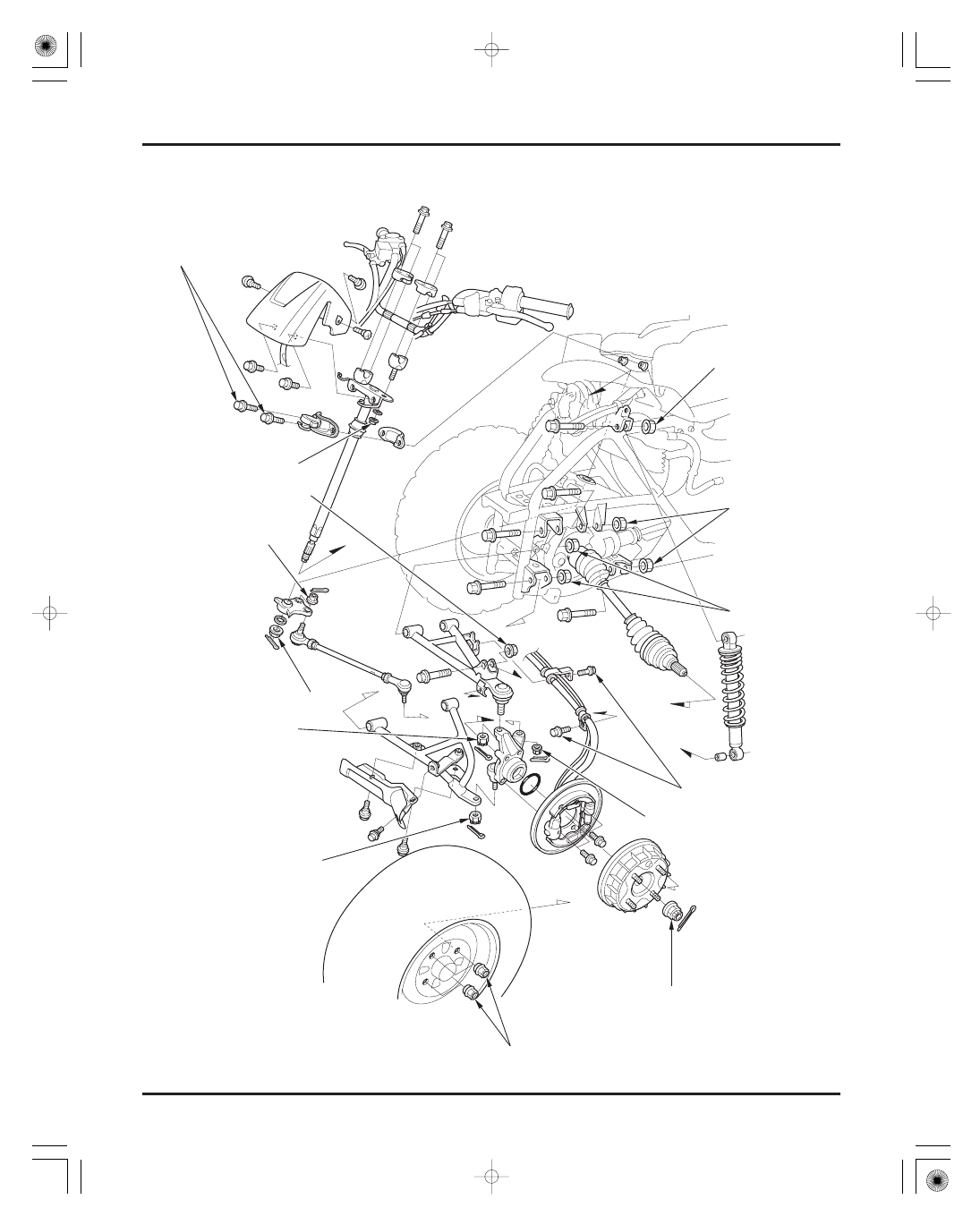
FRONT WHEEL/SUSPENSION/STEERING
12-0
29 N·m (3.0 kgf·m , 22 lbf·ft)
30 N·m (3.1 kgf·m , 22 lbf·ft)
44 N·m (4.5 kgf·m ,
33 lbf·ft)
108 N·m (11.0 kgf·m , 80 lbf·ft)
32 N·m (3.3 kgf·m , 24 lbf·ft)
39 N·m (4.0 kgf·m , 29 lbf·ft)
30 N·m (3.1 kgf·m , 22 lbf·ft)
54 N·m (5.5 kgf·m , 40 lbf·ft)
29 N·m (3.0 kgf·m , 22 lbf·ft)
64 N·m (6.5 kgf·m , 47 lbf·ft)
78 N·m (8.0 kgf·m , 58 lbf·ft)
54 N·m (5.5 kgf·m , 40 lbf·ft)
12 N·m (1.2 kgf·m , 9 lbf·ft)
44 N·m (4.5 kgf·m ,
33 lbf·ft)
FE model shown:
03/01/08 10:24:07 61HN400G_001