ATV Honda TRX350 TM/TE, TRX350 FM/FE. Service Manual - part 62


  Index      Manuals     ATV Honda TRX350 TM/TE, TRX350 FM/FE. Service Manual


Search            copyright infringement  


Content      ..     60      61      62      63     ..


ATV Honda TRX350 TM/TE, TRX350 FM/FE. Service Manual - part 62


CLUTCH/GEARSHIFT LINKAGE

9-20

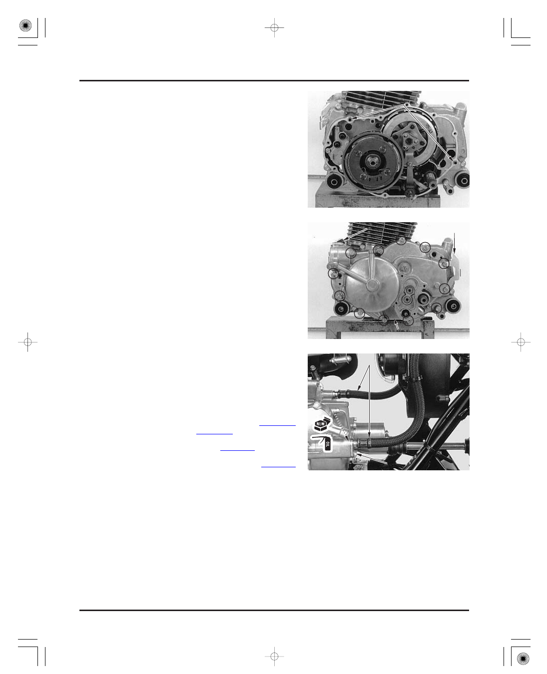
Install the two dowel pins and the front crankcase
cover, being careful not to damage the oil seal lips.

Install the twelve bolts with the engine side cover
stay and tighten them in a crisscross pattern in
several steps.

Install the oil level dipstick.

Coat new O-rings with engine oil and install them
onto the oil cooler hose joints.
Connect the oil cooler hoses into the crankcase
cover and tighten the joint bolts.

Install the left engine side cover with four screws.

Install the following:

Adjust the clutch system (page 3-17).

Fill the oil tank with recommended oil (page 3-11).

shift control motor reduction gears (page 21-23)
propeller shaft (page 15-23)

D

D

O

O

W

W

E

E

L

L

P

P

I

I

N

N

S

S

D

D

I

I

P

P

S

S

T

T

I

I

C

C

K

K

H

H

O

O

S

S

E

E

S

S

O

O

-

-

R

R

I

I

N

N

G

G

C

C

R

R

A

A

N

N

K

K

C

C

A

A

S

S

E

E

C

C

O

O

V

V

E

E

R

R

S

S

T

T

A

A

Y

Y

B

B

O

O

L

L

T

T

F M/ F E model

only:

03/01/08 10:04:33 61HN400E_029

-------------------------------------------------------------------------------------------------------------------------------------------------------------

MEMO

03/01/08 10:04:35 61HN400E_030

-------------------------------------------------------------------------------------------------------------------------------------------------------------

10-0

ALTERNATOR/STARTER CLUTCH

108 N·m (11.0 kgf·m , 80 lbf·ft)

03/01/08 10:06:02 61HN400F_001

-------------------------------------------------------------------------------------------------------------------------------------------------------------

SERVICE INFORMATION

10-1

TROUBLESHOOTING

10-1

RECOIL STARTER

10-2

ALTERNATOR STATOR

10-5

FLYWHEEL/STARTER CLUTCH

10-7

SERVICE INFORMATION

TROUBLESHOOTING

10

GENERAL

SPECIFICATION

TOOLS

TORQUE VALUES

Starter motor turns, but engine does not turn

STANDARD

ITEM

SERVICE LIMIT

10. ALTERNATOR/STARTER CLUTCH

10-1

The recoil starter can be removed with the engine installed in the frame. To service the alternator stator, flywheel and
starter clutch, the engine must be removed from the frame (these items can be serviced by removing the swingarm if no
additional engine work is needed).
Transmission lubricating oil is fed through the oil passages in the rear crankcase cover. Clean the oil passages before
installing the crankcase cover.
Refer to section 17 for alternator stator inspection.
Refer to section 19 for starter motor servicing.

Starter driven gear boss O.D.

45.660

45.673 (1.7976

1.7981)

Faulty starter clutch
Damaged starter reduction gear

Flywheel holder
Rotor puller

07725-0040000 or equivalent commercially available in U.S.A.
07YMC-HN40100

Starter clutch bolt
Recoil starter driven pulley bolt
Alternator stator bolt
Ignition pulse generator bolt

6 N·m (0.6 kgf·m , 4.3 lbf·ft)

10 N·m (1.0 kgf·m , 7 lbf·ft)

108 N·m (11.0 kgf·m , 80 lbf·ft)

23 N·m (2.3 kgf·m , 17 lbf·ft)

Apply locking agent to the threads
Apply oil to the threads and seating surface

Apply locking agent to the threads

45.65 (1.797)

Unit: mm (in)

03/01/08 10:06:17 61HN400F_002

-------------------------------------------------------------------------------------------------------------------------------------------------------------


REMOVAL

DISASSEMBLY

ALTERNATOR/STARTER CLUTCH

10-2

RECOIL STARTER

Remove the air cleaner housing (page 5-3).

Remove the wire clip from the recoil starter
housing.
Remove the three mounting bolts and the recoil
starter assembly.

Remove the following:

bolt
ratchet cover

ratchet guide and spring seat
spring
ratchet and pin

Check each part for wear or damage.

Separate the stopper from the starter grip and untie
the starter rope, then remove the stopper and grip
while holding the drive pulley.
Release the starter rope slowly.

Carefully remove the drive pulley from the starter
spring and pulley shaft of the housing.

R

R

A

A

T

T

C

C

H

H

E

E

T

T

G

G

U

U

I

I

D

D

E

E

A

A

N

N

D

D

S

S

P

P

R

R

I

I

N

N

G

G

S

S

E

E

A

A

T

T

C

C

L

L

I

I

P

P

B

B

O

O

L

L

T

T

A

A

N

N

D

D

C

C

O

O

V

V

E

E

R

R

R

R

A

A

T

T

C

C

H

H

E

E

T

T

S

S

T

T

O

O

P

P

P

P

E

E

R

R

R

R

O

O

P

P

E

E

D

D

R

R

I

I

V

V

E

E

P

P

U

U

L

L

L

L

E

E

Y

Y

R

R

E

E

C

C

O

O

I

I

L

L

S

S

T

T

A

A

R

R

T

T

E

E

R

R

A

A

S

S

S

S

E

E

M

M

B

B

L

L

Y

Y

P

P

I

I

N

N

S

S

P

P

R

R

I

I

N

N

G

G

G

G

R

R

I

I

P

P

03/01/08 10:06:27 61HN400F_003

-------------------------------------------------------------------------------------------------------------------------------------------------------------

ASSEMBLY

ALTERNATOR/STARTER CLUTCH

10-3

Remove the starter rope from the drive pulley.

Check the starter rope for wear or damage.

Check the starter spring for damage or break.

Remove the spring and replace it if it is broken.

Install the starter rope and tie a square knot as
shown.
Wrap the rope around the drive pulley in a counter-
clockwise direction as viewed from the ratchet side
as shown.

Install the starter spring by hooking the spring end
on the housing hook.

Apply grease to the pulley shaft groove.
Set the starter rope into the pulley cutout and
install the pulley by hooking the spring end on the
pulley hook.

Preload the starter spring by turning the pulley 4
turns counterclockwise and hold it.

R

R

O

O

P

P

E

E

H

H

o

o

o

o

k

k

S

S

P

P

R

R

I

I

N

N

G

G

C

C

U

U

T

T

O

O

U

U

T

T

P

P

U

U

L

L

L

L

E

E

Y

Y

H

H

o

o

o

o

k

k

W ear eye

protection and use

care when

removing. T he

spring may pop out

of the housing if

care is not used.

Ensure that the
spring does not

pop-out of the

housing during

installation.

03/01/08 10:06:35 61HN400F_004

-------------------------------------------------------------------------------------------------------------------------------------------------------------


INSTALLATION

ALTERNATOR/STARTER CLUTCH

10-4

Check that the recoil starter for smooth operation
by pulling the grip.

Install the recoil starter assembly and tighten the
three mounting bolts.
Install the wire clip into the starter housing.

Install the air cleaner housing (page 5-3).

Route the rope end through the housing hole while
the pulley remains held in place.
Route the rope end through the starter grip and
stopper, then tie it in a square knot.

Press the knot in the stopper and install the stopper
into the starter grip securely.

Apply grease to the ratchet and pivot pin sliding
surfaces.
Install the following:

pin
ratchet
spring
spring seat
ratchet guide

ratchet cover
bolt (apply engine oil to threads)

R

R

O

O

P

P

E

E

R

R

E

E

C

C

O

O

I

I

L

L

S

S

T

T

A

A

R

R

T

T

E

E

R

R

A

A

S

S

S

S

E

E

M

M

B

B

L

L

Y

Y

R

R

A

A

T

T

C

C

H

H

E

E

T

T

G

G

U

U

I

I

D

D

E

E

S

S

T

T

O

O

P

P

P

P

E

E

R

R

G

G

R

R

I

I

P

P

H

H

O

O

L

L

E

E

P

P

I

I

N

N

R

R

A

A

T

T

C

C

H

H

E

E

T

T

B

B

O

O

L

L

T

T

C

C

L

L

I

I

P

P

S

S

P

P

R

R

I

I

N

N

G

G

S

S

E

E

A

A

T

T

S

S

P

P

R

R

I

I

N

N

G

G

C

C

O

O

V

V

E

E

R

R

03/01/08 10:06:44 61HN400F_005

-------------------------------------------------------------------------------------------------------------------------------------------------------------


ALTERNATOR COVER REMOVAL

STATOR REMOVAL/INSTALLATION

ALTERNATOR/STARTER CLUTCH

10-5

ALTERNATOR STATOR

TORQUE:

TORQUE:

Remove the following:

two ignition pulse generator bolts and clamp
three stator bolts
grommet
stator/ignition pulse generator assembly

Apply locking agent to the ignition pulse generator
bolt threads.
Install the bolts with the clamp and tighten them.

Secure the ignition pulse generator with the clamp.

10 N·m (1.0 kgf·m , 7 lbf·ft)

6 N·m (0.6 kgf·m , 4.3 lbf·ft)

Set the assembly onto the alternator cover.
Apply sealant to the wire grommet grooves and
install the grommet into the cover groove securely.

Install the stator bolts and tighten them.

Remove the engine from the frame (section 6).
Remove the recoil starter (page 10-3).

Hold the recoil starter driven pulley using a screw-
driver and loosen the bolt.

Remove the bolt, O-ring and the driven pulley.

Remove the seven bolts, clamp and the alternator
cover.

Remove the dowel pins and gasket.

Remove the oil seal, being careful not to damage
the stator and ignition pulse generator.

G

G

R

R

O

O

M

M

M

M

E

E

T

T

S

S

T

T

A

A

T

T

O

O

R

R

G

G

A

A

S

S

K

K

E

E

T

T

D

D

O

O

W

W

E

E

L

L

P

P

I

I

N

N

S

S

A

A

L

L

T

T

E

E

R

R

N

N

A

A

T

T

O

O

R

R

C

C

O

O

V

V

E

E

R

R

B

B

O

O

L

L

T

T

A

A

N

N

D

D

O

O

-

-

R

R

I

I

N

N

G

G

C

C

L

L

A

A

M

M

P

P

I

I

G

G

N

N

I

I

T

T

I

I

O

O

N

N

P

P

U

U

L

L

S

S

E

E

G

G

E

E

N

N

E

E

R

R

A

A

T

T

O

O

R

R

C

C

L

L

A

A

M

M

P

P

D

D

R

R

I

I

V

V

E

E

N

N

P

P

U

U

L

L

L

L

E

E

Y

Y

T he cover ( stator)

is magnetically

attached to the

f lywheel, be

caref ul during

removal.

03/01/08 10:06:59 61HN400F_006

-------------------------------------------------------------------------------------------------------------------------------------------------------------

ALTERNATOR COVER INSTALLATION

ALTERNATOR/STARTER CLUTCH

10-6

TORQUE:

Install the recoil starter (page 10-5).
Install the engine (section 6).

108 N·m (11.0 kgf·m , 80 lbf·ft)

Install the dowel pins and a new gasket.

Install the alternator cover.
Install the seven bolts with the clamp and tighten
them.
Secure the alternator wire with the clamp.

Apply engine oil to a new oil seal and install it into
the alternator cover.

Install the recoil starter driven pulley into the
flywheel by aligning the wide tooth with the key
way.

Coat a new O-ring with engine oil and install it onto
the driven pulley bolt.
Apply engine oil to the pulley bolt threads and
seating surface and install it.

Tighten the pulley bolt by holding the driven pulley
using a screwdriver.

A

A

L

L

T

T

E

E

R

R

N

N

A

A

T

T

O

O

R

R

C

C

O

O

V

V

E

E

R

R

G

G

A

A

S

S

K

K

E

E

T

T

D

D

O

O

W

W

E

E

L

L

P

P

I

I

N

N

S

S

C

C

L

L

A

A

M

M

P

P

A

A

l

l

i

i

g

g

n

n

D

D

R

R

I

I

V

V

E

E

N

N

P

P

U

U

L

L

L

L

E

E

Y

Y

B

B

O

O

L

L

T

T

O

O

I

I

L

L

S

S

E

E

A

A

L

L

O

O

-

-

R

R

I

I

N

N

G

G

T he cover ( stator)

is magnetically

attached to the

f lywheel, be

caref ul not to get

anything caught

between these

parts when

installing.

03/01/08 10:07:10 61HN400F_007

-------------------------------------------------------------------------------------------------------------------------------------------------------------


FLYWHEEL REMOVAL

REAR CRANKCASE COVER REMOVAL

ALTERNATOR/STARTER CLUTCH

TOOL:
Rotor puller

10-7

FLYWHEEL/STARTER CLUTCH

Remove the following:

Remove the rear crankcase cover.

Remove the following:

alternator cover (page 10-5)
starter motor (page 19-4)
speed sensor bolts
speed sensor, sensor base and O-rings
nut, washer and reverse selector arm
twelve cover bolts, wire guide and side cover
stay
thermosensor connector

Remove the flywheel using the special tool.

07YMC-HN40100

Remove the following:

starter drive gear
woodruff key
needle bearing
washer

For gear position switch removal/installation, see
section 20.

thrust washer
two dowel pins
reduction gear and shaft

G

G

U

U

I

I

D

D

E

E

B

B

E

E

A

A

R

R

I

I

N

N

G

G

W

W

A

A

S

S

H

H

E

E

R

R

D

D

O

O

W

W

E

E

L

L

P

P

I

I

N

N

S

S

C

C

O

O

N

N

N

N

E

E

C

C

T

T

O

O

R

R

A

A

R

R

M

M

R

R

E

E

D

D

U

U

C

C

T

T

I

I

O

O

N

N

G

G

E

E

A

A

R

R

A

A

N

N

D

D

S

S

H

H

A

A

F

F

T

T

F

F

L

L

Y

Y

W

W

H

H

E

E

E

E

L

L

P

P

U

U

L

L

L

L

E

E

R

R

S

S

T

T

A

A

Y

Y

S

S

P

P

E

E

E

E

D

D

S

S

E

E

N

N

S

S

O

O

R

R

R

R

E

E

A

A

R

R

C

C

R

R

A

A

N

N

K

K

C

C

A

A

S

S

E

E

C

C

O

O

V

V

E

E

R

R

D

D

R

R

I

I

V

V

E

E

G

G

E

E

A

A

R

R

K

K

E

E

Y

Y

WASHER

03/01/08 10:07:25 61HN400F_008

-------------------------------------------------------------------------------------------------------------------------------------------------------------

TOOL:
Flywheel holder

STARTER CLUTCH REMOVAL/
INSPECTION

ALTERNATOR/STARTER CLUTCH

10-8

07725-0040000 or
equivalent commercially
available in U.S.A.

Remove the starter clutch assembly from the
flywheel.

Remove the sprag clutch from the starter clutch
outer.

Check the starter reduction gear and shaft for wear
or damage.

Check the starter clutch outer and sprag clutch for
abnormal wear or damage.

Make sure that the starter driven gear turns clock-
wise smoothly and does not turn counterclockwise.

Remove the driven gear while turning it clockwise.

Hold the flywheel with the special tool and remove
the starter clutch bolts.

D

D

R

R

I

I

V

V

E

E

N

N

G

G

E

E

A

A

R

R

C

C

L

L

U

U

T

T

C

C

H

H

O

O

U

U

T

T

E

E

R

R

F

F

L

L

Y

Y

W

W

H

H

E

E

E

E

L

L

H

H

O

O

L

L

D

D

E

E

R

R

S

S

P

P

R

R

A

A

G

G

C

C

L

L

U

U

T

T

C

C

H

H

B

B

O

O

L

L

T

T

S

S

03/01/08 10:07:36 61HN400F_009

-------------------------------------------------------------------------------------------------------------------------------------------------------------

STARTER CLUTCH INSTALLATION

FLYWHEEL INSTALLATION

ALTERNATOR/STARTER CLUTCH

TOOL:
Flywheel holder

TORQUE:

SERVICE LIMIT:

10-9

Check the starter driven gear teeth and needle
bearing for wear or damage.

Measure the starter driven gear boss O.D.

Lubricate the sprag clutch with engine oil and
install it into the starter clutch outer with the flange
side facing the flywheel side.

Apply locking agent to the starter clutch bolt
threads.
Install the starter clutch assembly onto the flywheel
and install the bolts.
Hold the flywheel with the special tool and tighten
the bolts.

07725-0040000 or
equivalent commercially
available in U.S.A.

Install the starter driven gear while turning it
clockwise.

23 N·m (2.3 kgf·m , 17 lbf·ft)

45.65 mm (1.797 in)

S

S

P

P

R

R

A

A

G

G

C

C

L

L

U

U

T

T

C

C

H

H

C

C

L

L

U

U

T

T

C

C

H

H

O

O

U

U

T

T

E

E

R

R

D

D

R

R

I

I

V

V

E

E

N

N

G

G

E

E

A

A

R

R

B

B

O

O

L

L

T

T

S

S

F

F

L

L

Y

Y

W

W

H

H

E

E

E

E

L

L

H

H

O

O

L

L

D

D

E

E

R

R

03/01/08 10:07:48 61HN400F_010

-------------------------------------------------------------------------------------------------------------------------------------------------------------

REAR CRANKCASE COVER
INSTALLATION

ALTERNATOR/STARTER CLUTCH

10-10

Lubricate the needle bearing with molybdenum oil
solution.
Install the washer and needle bearing onto the
crankshaft.

Clean any oil from the tapered portions of the
crankshaft and flywheel.

Install the woodruff key into the crankshaft key
groove.

Install the flywheel on the crankshaft, aligning the
key way with the woodruff key.

Temporarily install the recoil starter driven pulley
and bolt and tighten it to seat the flywheel (page
10-7).
Remove the driven pulley.

Apply molybdenum oil solution to the reduction
gear teeth and shaft.
Install the gear shaft with the reduction gear.

Apply engine oil to new reverse stopper shaft oil
seal and output shaft oil seal lips and install them
with the flat side facing out.

Clean the mating surfaces of the crankcase and
cover.
Blow through the oil passages in the rear crankcase
cover with compressed air.

Apply liquid sealant to the mating surface
(shadowed area) of the rear crankcase cover as
shown.

A

A

l

l

i

i

g

g

n

n

B

B

E

E

A

A

R

R

I

I

N

N

G

G

O

O

I

I

L

L

S

S

E

E

A

A

L

L

S

S

K

K

E

E

Y

Y

W

W

A

A

S

S

H

H

E

E

R

R

C

C

l

l

e

e

a

a

n

n

F

F

L

L

Y

Y

W

W

H

H

E

E

E

E

L

L

/

/

D

D

R

R

I

I

V

V

E

E

N

N

G

G

E

E

A

A

R

R

R

R

E

E

D

D

U

U

C

C

T

T

I

I

O

O

N

N

G

G

E

E

A

A

R

R

A

A

N

N

D

D

S

S

H

H

A

A

F

F

T

T

03/01/08 10:07:57 61HN400F_011

-------------------------------------------------------------------------------------------------------------------------------------------------------------


ALTERNATOR/STARTER CLUTCH

10-11

speed sensor (page 20-11)
starter motor (page 19-4)
alternator cover (page 10-5)

Install the two dowel pins and thrust washer.
Shift the transmission into neutral to align the
groove in the shift drum with the lug on the
crankcase.

Align the long end of the gear position switch pin
with the ‘‘N’’ mark on the switch plate.
Install the crankcase cover while aligning the
switch pin with the shift drum groove properly.

If the cover doesn’t install easily, remove it and
check the alignment of the switch pin and the shift
drum or the switch for damage.

Connect the thermosensor connector.
Install the twelve bolts with the wire guide and side
cover stay and tighten them in a crisscross pattern
in several steps.

Install the reverse selector arm with the slit facing
out by aligning the flat surfaces.
Install the arm nut with the washer and tighten it.

Install the following:

D

D

O

O

W

W

E

E

L

L

P

P

I

I

N

N

S

S

C

C

R

R

A

A

N

N

K

K

C

C

A

A

S

S

E

E

C

C

O

O

V

V

E

E

R

R

A

A

l

l

i

i

g

g

n

n

L

L

O

O

N

N

G

G

E

E

N

N

D

D

A

A

R

R

M

M

,

,

W

W

A

A

S

S

H

H

E

E

R

R

A

A

N

N

D

D

N

N

U

U

T

T

C

C

O

O

N

N

N

N

E

E

C

C

T

T

O

O

R

R

S

S

T

T

A

A

Y

Y

G

G

U

U

I

I

D

D

E

E

S

S

H

H

I

I

F

F

T

T

D

D

R

R

U

U

M

M

A

A

l

l

i

i

g

g

n

n

WASHER

Be caref ul not to

damage the switch

pin and the oil seal

lips.

Route the

thermosensor wire

through the wire

guide properly.

03/01/08 10:08:05 61HN400F_012

-------------------------------------------------------------------------------------------------------------------------------------------------------------

11-0

CRANKCASE/TRANSMISSION/CRANKSHAFT

03/01/08 10:08:09 61HN400F_013

-------------------------------------------------------------------------------------------------------------------------------------------------------------

SERVICE INFORMATION

11-1

TROUBLESHOOTING

11-2

CRANKCASE SEPARATION

11-3

TRANSMISSION

11-4

CRANKSHAFT/BALANCER

11-10

CRANKCASE BEARING
REPLACEMENT

11-12

CRANKCASE ASSEMBLY

11-16

SERVICE INFORMATION

11

GENERAL

SPECIFICATIONS

STANDARD

SERVICE LIMIT

ITEM

11-1

11. CRANKCASE/TRANSMISSION/CRANKSHAFT

The crankcase halves must be separated to service the transmission and crankshaft. To service these parts, the engine
must be removed from the frame (section 6).
Be careful not to damage the crankcase mating surfaces when servicing.
Transmission lubricating oil is fed through the oil passages in the crankcase. Clean the oil passages before assembling
the crankcase halves.

Reverse idle gear-to-shaft clearance
Runout
Big end side clearance
Big end radial clearance

Shift fork

Transmission

Crankshaft

Bushing-to-shaft
clearance

Reverse idle shaft O.D.

Gear I.D.

Gear bushing O.D.

Gear-to-bushing
clearance
Gear bushing I.D.

Mainshaft O.D.

Countershaft O.D.

I.D.
Claw thickness
Shaft O.D.

M4
M5
C1, C2, C3, CR
Reverse idle
M4
M5
C1, C2, C3, CR
M4

M4
M5
C3
at M4
at M5
at C3

M4, C3
M5

0.006

0.018 (0.0002

0.0007)

0.05

0.65 (0.002

0.026)

0.016

0.052 (0.0006

0.0020)

0.016

0.052 (0.0006

0.0020)

0.020

0.062 (0.0008

0.0024)

12.966

12.984 (0.5105

0.5112)

21.959

21.980 (0.8645

0.8654)

14.966

14.984 (0.5892

0.5899)

19.959

19.980 (0.7858

0.7866)

22.000

22.021 (0.8661

0.8670)

15.000

15.018 (0.5906

0.5913)

20.000

20.021 (0.7874

0.7882)

0.020

0.062 (0.0008

0.0024)

0.021

0.062 (0.0008

0.0024)

24.959

24.980 (0.9826

0.9835)

17.959

17.980 (0.7070

0.7079)

22.959

22.979 (0.9039

0.9047)

13.000

13.018 (0.5118

0.5125)

25.000

25.021 (0.9843

0.9851)

18.000

18.021 (0.7087

0.7095)

23.000

23.021 (0.9055

0.9063)

12.966

12.984 (0.5105

0.5112)

4.93

5.00 (0.194

0.197)

13.000

13.018 (0.5118

0.5125)

0.05 (0.002)

0.8 (0.03)

0.05 (0.002)

0.10 (0.004)

0.10 (0.004)

0.10 (0.004)

12.94 (0.509)

21.93 (0.863)

14.94 (0.588)

19.93 (0.785)

22.04 (0.868)

15.04 (0.592)

20.04 (0.789)

0.10 (0.004)

0.10 (0.004)

24.93 (0.981)

17.94 (0.706)

22.94 (0.903)

13.04 (0.513)

25.05 (0.986)

18.05 (0.711)

23.04 (0.907)

12.96 (0.510)

4.5 (0.18)

13.04 (0.513)

Unit: mm (in)

M5, C1, C2, C3, CR

03/01/08 10:08:37 61HN400F_014

-------------------------------------------------------------------------------------------------------------------------------------------------------------


Content      ..     60      61      62      63     ..