ATV Honda TRX350 TM/TE, TRX350 FM/FE. Service Manual - part 16


  Index      Manuals     ATV Honda TRX350 TM/TE, TRX350 FM/FE. Service Manual


Search            copyright infringement  


Content      ..     14      15      16      17     ..


ATV Honda TRX350 TM/TE, TRX350 FM/FE. Service Manual - part 16


15-0

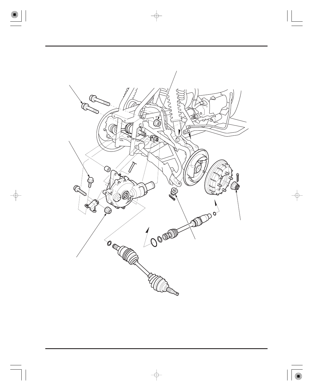
FRONT DRIVING MECHANISM (FM/FE model)

44 N·m (4.5 kgf·m , 33 lbf·ft)

44 N·m (4.5 kgf·m , 33 lbf·ft)

22 N·m (2.2 kgf·m , 16 lbf·ft)

22 N·m (2.2 kgf·m , 16 lbf·ft)

29 N·m (3.0 kgf·m , 22 lbf·ft)

78 N·m (8.0 kgf·m , 58 lbf·ft)

03/01/08 13:19:26 61HN400I_001

-------------------------------------------------------------------------------------------------------------------------------------------------------------

SERVICE INFORMATION

15-1

TROUBLESHOOTING 15-2

FRONT DRIVE SHAFT

15-3

DIFFERENTIAL REMOVAL

15-8

DIFFERENTIAL DISASSEMBLY/
INSPECTION

15-9

CASE BEARING REPLACEMENT

15-17

DIFFERENTIAL ASSEMBLY

15-19

DIFFERENTIAL INSTALLATION

15-23

SERVICE INFORMATION

15

GENERAL

SPECIFICATIONS

TORQUE VALUES

ITEM

STANDARD

SERVICE LIMIT

15-1

15. FRONT DRIVING MECHANISM (FM/FE models)

Front differential

Oil capacity

After draining

Upper and lower arm ball joint nut
Front wheel hub nut

Differential ring gear bolt
Differential pinion bearing lock nut
Differential case cover bolt

Differential mounting bolt (10 mm)

nut (10 mm)
bolt and nut (8 mm)

Apply grease to the threads and seating surface/Castle nut

22 N·m (2.2 kgf·m , 16 lbf·ft)

44 N·m (4.5 kgf·m , 33 lbf·ft)

44 N·m (4.5 kgf·m , 33 lbf·ft)

25 N·m (2.6 kgf·m , 19 lbf·ft)

49 N·m (5.0 kgf·m , 36 lbf·ft)

98 N·m (10.0 kgf·m , 72 lbf·ft)

49 N·m (5.0 kgf·m , 36 lbf·ft)

78 N·m (8.0 kgf·m , 58 lbf·ft)

29 N·m (3.0 kgf·m , 22 lbf·ft)

14

17 N·m (1.45

1.75 kgf·m ,

10

13 lbf·ft)

The differential assembly and propeller shaft must be removed together.
Perform the gear contact pattern and backlash inspection whenever you replace the bearings, gears or gear case. The
extension lines from the gear engagement surfaces should intersect at one point.
Protect the gear case with a shop towel or soft jaws while holding it in vise. Do not clamp it too tight as it could damage
the gear case.
When using the lock nut wrench, use a deflecting beam type torque wrench 20 inches long. The lock nut wrench
increases the torque wrench’s leverage, so the torque wrench reading will be less than the torque actually applied to the
lock nut. The specification given is the actual torque applied to the lock nut, not the reading on the torque wrench. Do not
overtighten the lock nut. The specification later in the text gives both actual and indicated.
Replace the ring and pinion gears as a set.
Replace the cam followers (12 pieces) as a set, and the cam followers, face cams and differential housing halves as an
assembly if the face cam, differential housing or cap is faulty.

Recommended oil
Gear backlash
Backlash difference
Slip torque

Face cam-to-housing distance
Differential housing cap depth
Cone spring free height

Castle nut

Special bolt
Stake/Lock nut
Apply locking agent to the threads

Lock nut

12 N·m (1.2 kgf·m ,

9 lbf·ft)

0.05

0.25 (0.002

0.010)

Hypoid gear oil SAE

80

241 cm (8.2 US oz , 8.5 Imp oz)
275 cm (9.3 US oz , 9.7 Imp oz)

6.3

6.7 (0.25

0.26)

9.55

9.65 (0.376

0.380)

2.8 (0.11)

0.4 (0.02)
0.2 (0.01)

6.3 (0.25)
9.55 (0.376)
2.6 (0.10)

Unit: mm (in)

After disassembly

03/01/08 13:19:45 61HN400I_002

-------------------------------------------------------------------------------------------------------------------------------------------------------------

×
×

×

×

×

TOOLS

FRONT DRIVING MECHANISM (FM/FE models)

Abnormal noises when turning

Gear noises while coasting

Gear noises while running

Consistent noise during cruising

Over heating

Oil leak

Abnormal noises at start or during acceleration

TROUBLESHOOTING

15-2

Worn or damaged ring gear bearing
Worn or damaged face cam and cam follower
Worn or damaged differential housing groove
Worn cone spring or shim

Damage or chipped gears

Oil level too low
Foreign matter contaminating gear oil
Chipped or damaged gears
Improper tooth contact between ring gear and pinion gear

Oil level too low
Foreign matter contaminating gear oil
Worn or damaged bearing
Worn or damaged ring gear and pinion gear
Deformed ring gear or differential case
Improper tooth contact between ring gear and pinion gear

Oil level too low
Insufficient backlash between ring gear and pinion gear

Oil level too high
Clogged breather
Damaged seals
Loose case cover bolt

Excessive backlash between ring gear and pinion gear
Worn differential splines
Loose fasteners
Worn cone spring or shim

07749-0010000
07746-0010800
07746-0010400
07746-0041200
07746-0041100
07746-0020100
07746-0030100
07746-0020200
07746-0020400
07MAC-SL00200
07KMK-HC50101 or 07KMK-HC5010A (U.S.A. only)
07916-ME50001
07HMC-MM80110 or 07HMC-MM8011A (U.S.A. only)
07965-VM00200 not available in U.S.A. or 07931-ME4010B and 07931-HB3020A

(U.S.A. only) and 07YMF-HN4010A (U.S.A. only)

07YMC-001010A (U.S.A. only)
can use collet of 07936-KC10500
07936-KC10100
07WMC-KFG0100
07936-KC10200
07741-0010201
07936-3710200 or 07936-371020A (U.S.A. only)
07936-3710100
07YME-HN4010A (U.S.A. only)
07YMF-HN4010A (U.S.A. only)

Driver
Attachment, 22

24 mm

Attachment, 52

55 mm

Pilot, 14 mm
Pilot, 28 mm
Driver, 22 mm I.D.
Driver, 40 mm I.D.
Attachment, 15 mm I.D.
Attachment, 20 mm I.D.
Ball joint remover, 28 mm
Differential inspection tool
Lock nut wrench, 34

44 mm

Pinion puller base
Assembly shaft

Remover shaft, 14 mm

Remover shaft, 15 mm
Bearing remover, 14 mm
Bearing remover, 15 mm
Remover weight
Remover weight
Remover handle
Differential bearing ring compressor
Threaded adapter, 16 1.5 12 1.25 mm

03/01/08 13:19:59 61HN400I_003

-------------------------------------------------------------------------------------------------------------------------------------------------------------

REMOVAL

FRONT DRIVING MECHANISM (FM/FE models)

TOOL:
Ball joint remover, 28 mm

15-3

FRONT DRIVE SHAFT

Remove the front wheel (page 12-7).

Remove the cotter pin and loosen the hub nut.

Remove the cotter pins and loosen the ball joint
nuts.
Release the ball joints, using the special tool
according to the instructions on page 12-12.

07MAC-SL00200

Remove the hub nut and joint nuts and separate the
brake panel assembly from the drive shaft.
Support the brake panel assembly so that it does
not hang from the brake hose.

Hold the inboard joint of the drive shaft and tug
firmly to force the stopper ring at the drive shaft
end past the groove while prying with a
screwdriver.

N

N

U

U

T

T

C

C

O

O

T

T

T

T

E

E

R

R

P

P

I

I

N

N

N

N

U

U

T

T

C

C

O

O

T

T

T

T

E

E

R

R

P

P

I

I

N

N

D

D

R

R

I

I

V

V

E

E

S

S

H

H

A

A

F

F

T

T

I

I

N

N

B

B

O

O

A

A

R

R

D

D

J

J

O

O

I

I

N

N

T

T

B

B

R

R

A

A

K

K

E

E

P

P

A

A

N

N

E

E

L

L

A

A

S

S

S

S

E

E

M

M

B

B

L

L

Y

Y

B

B

A

A

L

L

L

L

J

J

O

O

I

I

N

N

T

T

R

R

E

E

M

M

O

O

V

V

E

E

R

R

Do not twist the

brake hose.

T o prevent

damage to the

dif f erential oil

seal, hold the

inboard joint

horizontal until the

drive shaf t is clear

of the dif f erential.

03/01/08 13:20:10 61HN400I_004

-------------------------------------------------------------------------------------------------------------------------------------------------------------


DISASSEMBLY/INSPECTION

FRONT DRIVING MECHANISM (FM/FE models)

15-4

Check the boots for cuts or other damage.
Check the drive shaft joints for excessive play or
noise by moving the joints in a circular direction.
If the outboard joint seems to be worn or damaged,
the drive shaft must be replaced.

Bend up the lock tabs and raise the band end to
loosen the boot bands on the inboard side.
Remove the boot band B.

Release the boot off the inboard joint.

Remove the following:

stopper ring
inboard joint

snap ring
bearing
inboard boots
boot band C

To replace the outboard boot, first remove the
inboard boots as described in following steps.
Then remove bands and the outboard boot off
the inboard end of the shaft.
The outboard joint can not be disassembled.

O

O

U

U

T

T

B

B

O

O

A

A

R

R

D

D

J

J

O

O

I

I

N

N

T

T

B

B

O

O

O

O

T

T

S

S

I

I

N

N

B

B

O

O

A

A

R

R

D

D

J

J

O

O

I

I

N

N

T

T

T

T

A

A

B

B

S

S

B

B

A

A

N

N

D

D

C

C

S

S

T

T

O

O

P

P

P

P

E

E

R

R

R

R

I

I

N

N

G

G

B

B

E

E

A

A

R

R

I

I

N

N

G

G

S

S

N

N

A

A

P

P

R

R

I

I

N

N

G

G

B

B

O

O

O

O

T

T

B

B

A

A

N

N

D

D

E

E

N

N

D

D

B

B

A

A

N

N

D

D

B

B

I

I

N

N

B

B

O

O

A

A

R

R

D

D

J

J

O

O

I

I

N

N

T

T

Replace the bands

with new ones

whenever

removing them.

03/01/08 13:20:21 61HN400I_005

-------------------------------------------------------------------------------------------------------------------------------------------------------------


ASSEMBLY

FRONT DRIVING MECHANISM (FM/FE models)

15-5

Check the following for wear or damage.

bearing cage
race
steel balls
inboard joint

Remove the following:

boot band C and A
outboard boot

B

B

A

A

N

N

D

D

C

C

O

O

U

U

T

T

B

B

O

O

A

A

R

R

D

D

B

B

O

O

O

O

T

T

O

O

U

U

T

T

B

B

O

O

A

A

R

R

D

D

J

J

O

O

I

I

N

N

T

T

B

B

A

A

N

N

D

D

A

A

B

B

A

A

N

N

D

D

C

C

I

I

N

N

B

B

O

O

A

A

R

R

D

D

B

B

O

O

O

O

T

T

S

S

T

T

O

O

P

P

P

P

E

E

R

R

R

R

I

I

N

N

G

G

B

B

E

E

A

A

R

R

I

I

N

N

G

G

S

S

N

N

A

A

P

P

R

R

I

I

N

N

G

G

I

I

N

N

B

B

O

O

A

A

R

R

D

D

J

J

O

O

I

I

N

N

T

T

B

B

A

A

N

N

D

D

B

B

I

I

N

N

B

B

O

O

A

A

R

R

D

D

J

J

O

O

I

I

N

N

T

T

B

B

E

E

A

A

R

R

I

I

N

N

G

G

B

B

A

A

N

N

D

D

A

A

B

B

O

O

O

O

T

T

B

B

A

A

N

N

D

D

C

C

D

D

R

R

I

I

V

V

E

E

S

S

H

H

A

A

F

F

T

T

Replace their

components as an

assembly.

03/01/08 13:20:31 61HN400I_006

-------------------------------------------------------------------------------------------------------------------------------------------------------------


15-6

FRONT DRIVING MECHANISM (FM/FE models)

outboard boot
new boot bands C
inboard boot

Pack the outboard joint with 30

50 g of molybde-

num disulfide grease.

Install the following:

Do not tighten the bands at this time.

Install the bearing with the small O.D. facing to the
drive shaft.
Install the snap ring with the chamfered side facing
to the bearing.

Pack the inboard joint with 40

60 g of molybde-

num disulfide grease.

Install the inboard joint over the bearing.
Install the stopper ring into the groove the in the
inboard joint properly.

Each boot has an identification mark; ‘‘BJ68L’’ for
the outboard and ‘‘BJ68’’ for the inboard.

Note the installation direction of the boot bands.

O

O

U

U

T

T

B

B

O

O

A

A

R

R

D

D

B

B

O

O

O

O

T

T

I

I

N

N

B

B

O

O

A

A

R

R

D

D

B

B

O

O

O

O

T

T

O

O

U

U

T

T

B

B

O

O

A

A

R

R

D

D

B

B

O

O

O

O

T

T

B

B

J

J

6

6

8

8

L

L

B

B

J

J

6

6

8

8

S

S

N

N

A

A

P

P

R

R

I

I

N

N

G

G

(

(

4

4

0

0

6

6

0

0

g

g

)

)

S

S

T

T

O

O

P

P

P

P

E

E

R

R

R

R

I

I

N

N

G

G

I

I

N

N

B

B

O

O

A

A

R

R

D

D

B

B

O

O

O

O

T

T

B

B

E

E

A

A

R

R

I

I

N

N

G

G

Forward direction

B

B

A

A

N

N

D

D

B

B

A

A

N

N

D

D

S

S

C

C

(

(

3

3

0

0

5

5

0

0

g

g

)

)

03/01/08 13:20:42 61HN400I_007

-------------------------------------------------------------------------------------------------------------------------------------------------------------

INSTALLATION

FRONT DRIVING MECHANISM (FM/FE models)

15-7

DRIVE SHAFT LENGTH: Left/Right:

Install a new stopper ring into the groove in the
inboard joint spline.

Install the drive shaft by holding the inboard joint
until the stopper ring seats in the groove of the
differential.

Make sure that the stopper ring is seated properly
by pulling on the inboard joint lightly.

344.8

354.8 mm (13.57

13.97 in)

Adjust the length of the drive shaft to the figure
given below.

Install the boot bands C onto the boots.
Install new boot band A onto the outboard boot and
the band B onto the inboard boot.

Bend down the band end and secure it with the lock
tabs. Tap the lock tabs with a plastic hammer.

B

B

A

A

N

N

D

D

A

A

B

B

A

A

N

N

D

D

C

C

T

T

A

A

B

B

S

S

B

B

A

A

N

N

D

D

C

C

B

B

A

A

N

N

D

D

B

B

S

S

T

T

O

O

P

P

P

P

E

E

R

R

R

R

I

I

N

N

G

G

I

I

N

N

B

B

O

O

A

A

R

R

D

D

J

J

O

O

I

I

N

N

T

T

O

O

U

U

T

T

B

B

O

O

A

A

R

R

D

D

J

J

O

O

I

I

N

N

T

T

I

I

N

N

B

B

O

O

A

A

R

R

D

D

J

J

O

O

I

I

N

N

T

T

B

B

A

A

N

N

D

D

E

E

N

N

D

D

See page 15-6 f or

band installation

direction.

Be caref ul not to

damage the oil

seal in the

dif f erential gear

case.

03/01/08 13:20:53 61HN400I_008

-------------------------------------------------------------------------------------------------------------------------------------------------------------


15-8

TORQUE:

TORQUE:

DIFFERENTIAL REMOVAL

FRONT DRIVING MECHANISM (FM/FE models)

Install the brake panel assembly over the drive
shaft and onto the suspension arms.

Install and tighten each joint nut to the specified
torque and further tighten until its grooves align
with the cotter pin hole.

Install new cotter pins.

Install the hub nut and tighten it to the specified
torque and further tighten until its grooves align
with the cotter pin hole.

Install a new cotter pin.

Install the front wheel (page 12-8).

Drain the differential oil (page 3-13).

Remove the following:

Disconnect the breather tube.

Remove the following mounting fasteners:

29 N·m (3.0 kgf·m , 22 lbf·ft)

78 N·m (8.0 kgf·m , 58 lbf·ft)

left front mud guard (page 2-6)
one drive shaft (page 15-3)

8 mm nut and bolt
10 mm nut, spacer, and two bolts

B

B

R

R

A

A

K

K

E

E

P

P

A

A

N

N

E

E

L

L

A

A

S

S

S

S

E

E

M

M

B

B

L

L

Y

Y

N

N

U

U

T

T

C

C

O

O

T

T

T

T

E

E

R

R

P

P

I

I

N

N

N

N

U

U

T

T

C

C

O

O

T

T

T

T

E

E

R

R

P

P

I

I

N

N

B

B

R

R

E

E

A

A

T

T

H

H

E

E

R

R

T

T

U

U

B

B

E

E

B

B

O

O

L

L

T

T

N

N

U

U

T

T

A

A

N

N

D

D

B

B

O

O

L

L

T

T

N

N

U

U

T

T

,

,

B

B

O

O

L

L

T

T

A

A

N

N

D

D

S

S

P

P

A

A

C

C

E

E

R

R

03/01/08 13:21:05 61HN400I_009

-------------------------------------------------------------------------------------------------------------------------------------------------------------

PROPELLER SHAFT REMOVAL

ASSEMBLY INSPECTION

FRONT DRIVING MECHANISM (FM/FE models)

PROPELLER SHAFT

15-9

DIFFERENTIAL DISASSEMBLY/

INSPECTION

two 8 mm bolts
mounting bracket

Check the splines of the propeller shaft for wear or
damage.
If damaged, check the pinion joint and drive shaft
joint also.
Check the dust seals for fatigue or damage.
Check the boots for cuts or damage.

Remove the boot band from the dust boot of the
differential side and release the dust boot off the
pinion joint.
Separate the propeller shaft from the differential by
pulling it to force the stopper ring at the propeller
shaft end past the groove in the pinion joint.

Remove the boot band from the dust boot of the
propeller shaft joint side and release the dust boot
off the joint to remove the propeller shaft joint and
spring.

Move the differential forward for maximum clear-
ance between the propeller shaft joint and engine.

Pull the propeller shaft joint forward, then separate
it from the engine (output shaft joint).

Separate the other drive shaft from the differential
as you remove it.
Remove the differential assembly out of the frame.

B

B

O

O

L

L

T

T

S

S

B

B

R

R

A

A

C

C

K

K

E

E

T

T

P

P

R

R

O

O

P

P

E

E

L

L

L

L

E

E

R

R

S

S

H

H

A

A

F

F

T

T

J

J

O

O

I

I

N

N

T

T

O

O

U

U

T

T

P

P

U

U

T

T

J

J

O

O

I

I

N

N

T

T

S

S

H

H

A

A

F

F

T

T

B

B

A

A

N

N

D

D

B

B

O

O

O

O

T

T

P

P

R

R

O

O

P

P

E

E

L

L

L

L

E

E

R

R

S

S

H

H

A

A

F

F

T

T

B

B

A

A

N

N

D

D

B

B

O

O

O

O

T

T

P

P

R

R

O

O

P

P

E

E

L

L

L

L

E

E

R

R

S

S

H

H

A

A

F

F

T

T

J

J

O

O

I

I

N

N

T

T

S

S

P

P

R

R

I

I

N

N

G

G

P

P

I

I

N

N

I

I

O

O

N

N

J

J

O

O

I

I

N

N

T

T

03/01/08 13:21:18 61HN400I_010

-------------------------------------------------------------------------------------------------------------------------------------------------------------

×

×

DIFFERENTIAL

TOOL:
Differential inspection tool

TOOLS:
Pinion puller base

Assembly shaft

Puller shaft
Threaded adapter,

Special nut

SERVICE LIMIT:

SERVICE LIMIT:

STANDARD:

BACKLASH INSPECTION

FRONT DRIVING MECHANISM (FM/FE models)

16

1.5

12

1.25 mm

15-10

Turn the pinion joint and check that the gear turns
smoothly and quietly without binding.

If the gears do not turn smoothly or quietly, the
gears and/or bearing may be damaged or faulty.
They must be checked after disassembly; replace
them if necessary.

If the difference in measurements exceeds the
service limit, it indicates that the bearing is not
installed squarely, or the case is deformed.
Inspect the bearings and case.

If the backlash is excessive, replace the ring gear
left side shim with a thinner one.
If the backlash is too small, replace the ring gear
left side shim with a thicker one.
Backlash changed by about 0.06 mm (0.002 in)
when thickness of the shim is changed by 0.10 mm
(0.004 in).

0.2 mm (0.01 in)

Remove the dial indicator. Turn the ring gear 120°
and measure backlash. Repeat this procedure once
more.
Compare the difference of the three measurements.

0.4 mm (0.02 in)

0.05

0.25 mm (0.002

0.010 in)

Remove the oil filler cap and set a horizontal type
dial indicator on the ring gear through the filler
hole.
Turn the ring gear back and forth to read backlash.

07KMK-HC50101 or
07KMK-HC5010A
(U.S.A. only)

Set the differential case into a jig or vise with soft
jaws.
Install the differential inspection tool into the right
side of the differential.

07HMC-MM80110 or
07HMC-MM8011A
(U.S.A. only)
07965-VM00200

07931-ME4010B and
07YMF-HN4010A
(U.S.A. only) and
07931-HB3020A
(U.S.A. only)

P

P

U

U

L

L

L

L

E

E

R

R

B

B

A

A

S

S

E

E

R

R

I

I

G

G

H

H

T

T

S

S

H

H

I

I

M

M

L

L

E

E

F

F

T

T

S

S

H

H

I

I

M

M

I

I

N

N

S

S

P

P

E

E

C

C

T

T

I

I

O

O

N

N

T

T

O

O

O

O

L

L

A

A

S

S

S

S

E

E

M

M

B

B

L

L

Y

Y

S

S

H

H

A

A

F

F

T

T

Hold the pinion gear with the special tools.

not available in U.S.A. or

03/01/08 13:21:32 61HN400I_011

-------------------------------------------------------------------------------------------------------------------------------------------------------------


DIFFERENTIAL CASE DISASSEMBLY

BEARING INSPECTION

FRONT DRIVING MECHANISM (FM/FE models)

15-11

Ring gear shims:
A: (thinnest):
K: (standard):
W: (thickest):

Turn the inner race of each bearing in the gear case
and case cover with your finger. The bearings
should turn smoothly and quietly. Also check that
the bearing outer race fits tightly in the case or
cover.

For ring gear bearing replacement, see page 15-17.
For pinion gear removal and bearing replacement,
see page 15-16 an15-18.

Twenty-three different thickness shims are
available from the thinnest (0.50 mm thickness:
A) shim to the thickest (1.60 mm thickness: W) in
intervals of 0.05 mm.

Change the right side shim and equal thickness and
opposite amount of what the left side shim was
changed; if the left shim was replaced with a 0.10
mm (0.004 in) thicker shim, replace the right shim
with one that is 0.10 mm (0.004 in) thinner.

Remove the cover bolts in a crisscross pattern in
several steps.

Pry the cover at the prying points using a screw-
driver and remove the case cover.

Remove the differential assembly and shims.

B

B

O

O

L

L

T

T

S

S

C

C

A

A

S

S

E

E

C

C

O

O

V

V

E

E

R

R

D

D

I

I

F

F

F

F

E

E

R

R

E

E

N

N

T

T

I

I

A

A

L

L

A

A

S

S

S

S

E

E

M

M

B

B

L

L

Y

Y

S

S

H

H

I

I

M

M

S

S

0.50 mm (0.020 in)
1.00 mm (0.039 in)
1.60 mm (0.063 in)

P

P

R

R

Y

Y

I

I

N

N

G

G

P

P

O

O

I

I

N

N

T

T

S

S

03/01/08 13:21:42 61HN400I_012

-------------------------------------------------------------------------------------------------------------------------------------------------------------

GEAR TOOTH CONTACT PATTERN
CHECK

FRONT DRIVING MECHANISM (FM/FE models)

15-12

TORQUE: 10 mm bolt:

8 mm bolt:

Remove the oil filler cap.

Rotate the ring gear several times in both
directions of rotation.

Check the gear tooth contact pattern through the oil
filler hole.
The pattern is indicated by the Prussian Blue
applied to the pinion.
Contact is normal if the Prussian Blue is transferred
to the approximate center of each tooth, but
slightly to the heel side and to the flank side.

If the patterns are not correct, remove and change
the pinion shim with one of an alternate thickness.

Clean sealing material off the mating surfaces of
the differential case and cover, being careful not to
damage them.

Apply thin coat of Prussian Blue to the pinion gear
teeth for a tooth contact pattern check.

Install the ring gear shims onto the differential
assembly.

Install the differential assembly into the gear case.

Install the case cover and tighten the bolts in
several steps until the cover evenly touches the
gear case. Then, while rotating the pinion gear,
tighten the bolts to the specified torque in a
crisscross pattern in several steps.

49 N·m (5.0 kgf·m , 36 lbf·ft)
25 N·m (2.6 kgf·m , 19 lbf·ft)

A

A

p

p

p

p

l

l

y

y

P

P

r

r

u

u

s

s

s

s

i

i

a

a

n

n

B

B

l

l

u

u

e

e

L

L

E

E

F

F

T

T

S

S

H

H

I

I

M

M

R

R

I

I

G

G

H

H

T

T

S

S

H

H

I

I

M

M

D

D

I

I

F

F

F

F

E

E

R

R

E

E

N

N

T

T

I

I

A

A

L

L

A

A

S

S

S

S

E

E

M

M

B

B

L

L

Y

Y

1

1

0

0

m

m

m

m

B

B

O

O

L

L

T

T

S

S

C

C

A

A

S

S

E

E

C

C

O

O

V

V

E

E

R

R

8

8

m

m

m

m

B

B

O

O

L

L

T

T

S

S

N

N

O

O

R

R

M

M

A

A

L

L

:

:

H

H

E

E

E

E

L

L

T

T

O

O

E

E

F

F

A

A

C

C

E

E

F

F

L

L

A

A

N

N

K

K

F

F

L

L

A

A

N

N

K

K

D

D

R

R

I

I

V

V

E

E

S

S

I

I

D

D

E

E

C

C

O

O

A

A

S

S

T

T

S

S

I

I

D

D

E

E

F

F

A

A

C

C

E

E

K eep dust and dirt

out of the case and

cover.

It is important to

turn the pinion

while tightening

the bolts. If the

ring gear shim is

too thick, the

gears will lock

af ter only light

tightening.

03/01/08 13:21:54 61HN400I_013

-------------------------------------------------------------------------------------------------------------------------------------------------------------

DIFFERENTIAL INSPECTION

FRONT DRIVING MECHANISM (FM/FE models)

TOOL:
Differential inspection tool

Pinion shims:
L:
M:
N:
A:
B:

C:
D:
E:
F:
G:

STANDARD:

SERVICE LIMIT:

15-13

Replace the pinion shim with a thicker one if the
contact pattern is too high, toward the face.

Replace the pinion shim with a thinner one if the
contact pattern is too low, toward the flank.

The pattern will shift about 0.5

1.0 mm (0.02

0.04 in) when the thickness of the shim is changed
by 0.12 mm (0.005 in).

For pinion shim replacement, see page 15-16.

Install the inspection tools into both sides of the
differential.

Hold the flat surface of the tool with a bench vise.
Attach a torque wrench to the other tool and
measure the limited slip torque.

14

17 N·m (1.45

1.75 kgf·m ,

10

13 lbf·ft)

07KMK-HC50101 or
07KMK-HC5010A
(U.S.A. only)

12 N·m (1.2 kgf·m , 9 lbf·ft)

If the slip torque is out of specification,
disassemble the differential and perform the
components inspection (page 15-14) since the
differential may be faulty.

T

T

O

O

O

O

H

H

I

I

G

G

H

H

:

:

P

P

I

I

N

N

I

I

O

O

N

N

S

S

H

H

I

I

M

M

T

T

O

O

O

O

L

L

O

O

W

W

:

:

F

F

L

L

A

A

N

N

K

K

F

F

L

L

A

A

N

N

K

K

P

P

I

I

N

N

I

I

O

O

N

N

S

S

H

H

I

I

M

M

1.64 mm (0.064 in)
1.70 mm (0.067 in)
1.76 mm (0.069 in)
1.82 mm (0.072 in)
1.88 mm (0.074 in)

1.94 mm (0.076 in)
2.00 mm (0.079 in)
2.06 mm (0.081 in)
2.12 mm (0.083 in)
2.18 mm (0.086 in)

I

I

N

N

S

S

P

P

E

E

C

C

T

T

I

I

O

O

N

N

T

T

O

O

O

O

L

L

S

S

D

D

R

R

I

I

V

V

E

E

S

S

I

I

D

D

E

E

C

C

O

O

A

A

S

S

T

T

S

S

I

I

D

D

E

E

D

D

R

R

I

I

V

V

E

E

S

S

I

I

D

D

E

E

C

C

O

O

A

A

S

S

T

T

S

S

I

I

D

D

E

E

F

F

A

A

C

C

E

E

F

F

A

A

C

C

E

E

03/01/08 13:22:05 61HN400I_014

-------------------------------------------------------------------------------------------------------------------------------------------------------------


DIFFERENTIAL DISASSEMBLY

DIFFERENTIAL COMPONENTS
INSPECTION

FRONT DRIVING MECHANISM (FM/FE models)

DIFFERENTIAL CAP

SERVICE LIMIT:

15-14

Check the sliding surface of the cap for damage or
discoloration.
Measure the depth of the cap from the mating
surface as shown.

differential cap
cone spring
shim

left face cam
six cam followers A and six cam followers B
right face cam

9.55 mm (0.376 in)

Remove the six bolts, then place the differential
assembly with the housing side down, and remove
the ring gear.

Remove the following:

8

8

m

m

m

m

B

B

O

O

L

L

T

T

S

S

R

R

I

I

N

N

G

G

G

G

E

E

A

A

R

R

F

F

A

A

C

C

E

E

C

C

A

A

M

M

S

S

P

P

R

R

I

I

N

N

G

G

S

S

H

H

I

I

M

M

C

C

A

A

P

P

C

C

A

A

M

M

F

F

O

O

L

L

L

L

O

O

W

W

E

E

R

R

S

S

A

A

A

A

N

N

D

D

B

B

F

F

A

A

C

C

E

E

C

C

A

A

M

M

D

D

I

I

F

F

F

F

E

E

R

R

E

E

N

N

T

T

I

I

A

A

L

L

H

H

O

O

U

U

S

S

I

I

N

N

G

G

If the dif f erential

housing, cap and

f ace cam are

f aulty, replace the

dif f erential as an

assembly.

03/01/08 13:22:16 61HN400I_015

-------------------------------------------------------------------------------------------------------------------------------------------------------------

DIFFERENTIAL HOUSING/FACE CAM/
CAM FOLLOWER

SIDE CONE SPRING

SERVICE LIMIT:

SERVICE LIMIT:

15-15

FRONT DRIVING MECHANISM (FM/FE models)

Check the spring for damage.
Measure the height of the cone spring.

Check the sliding surface and grooves of the
housing for damage or discoloration.

Check the shim, face cams and followers for
damage.

Temporarily assemble the differential housing, face
cams and cam followers (page 15-21).
Measure the height of the face cam from the
housing mating surface as shown while applying a
load of 1.47 kN (150 kgf) to the face cam boss using
a hydraulic press.

If the height exceeds the limit, replace the
differential as an assembly.

6.3 mm (0.25 in)

2.6 mm (0.10 in)

F

F

A

A

C

C

E

E

C

C

A

A

M

M

C

C

A

A

M

M

F

F

O

O

L

L

L

L

O

O

W

W

E

E

R

R

S

S

P

P

R

R

I

I

N

N

G

G

H

H

O

O

U

U

S

S

I

I

N

N

G

G

1.47 kN (150 kgf)

Replace the cam

f ollowers as a set

( 12 pieces).

03/01/08 13:22:26 61HN400I_016

-------------------------------------------------------------------------------------------------------------------------------------------------------------


Content      ..     14      15      16      17     ..