ATV Honda TRX350 TM/TE, TRX350 FM/FE. Service Manual - part 14
INSPECTION
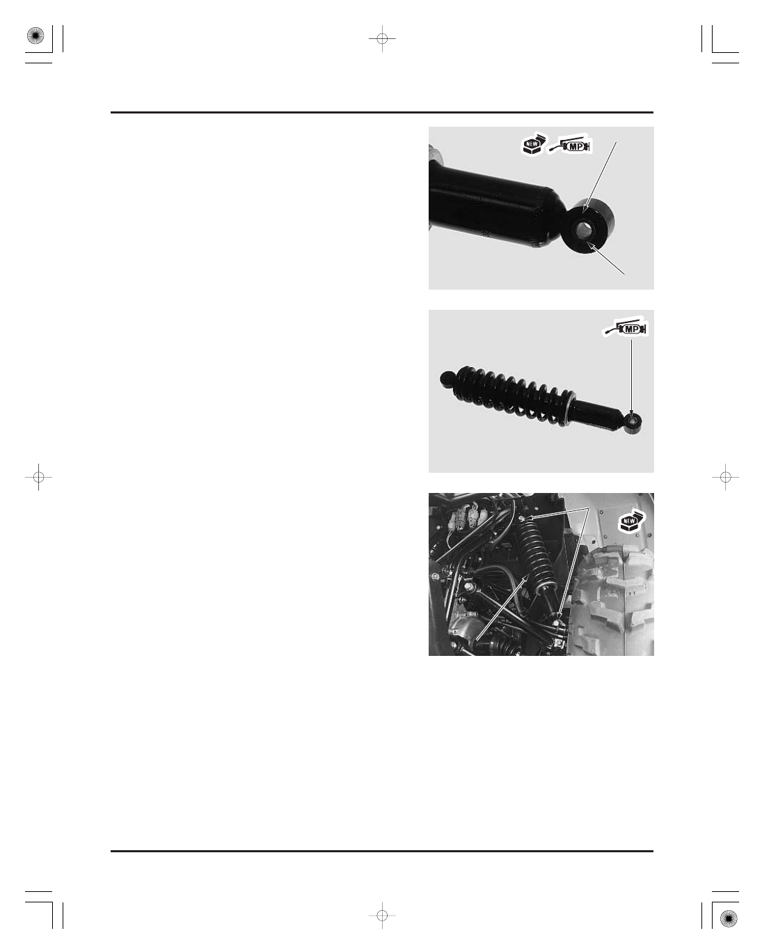
INSTALLATION
FRONT WHEEL/SUSPENSION/STEERING
12-24
TORQUE: Upper/Lower:
Apply molybdenum disulfide paste to the lower
bushing of the shock absorber.
Coat new dust seal lips with molybdenum disulfide
paste and install them into the lower pivot until
they are fully seated.
Install the lower pivot collar.
Install the shock absorber with the mounting bolts
from front side.
Install new mounting nuts and tighten them.
30 N·m (3.1 kgf·m , 22 lbf·ft)
Remove the lower pivot collar and dust seals.
Check the pivot collar for wear or damage.
Check the bushings for wear or damage.
Check the damper unit for leakage or other damage.
Replace the shock absorber assembly if necessary.
S
S
H
H
O
O
C
C
K
K
A
A
B
B
S
S
O
O
R
R
B
B
E
E
R
R
C
C
O
O
L
L
L
L
A
A
R
R
D
D
U
U
S
S
T
T
S
S
E
E
A
A
L
L
B
B
O
O
L
L
T
T
S
S
A
A
N
N
D
D
N
N
U
U
T
T
S
S
03/01/08 10:28:55 61HN400G_025