ATV Honda TRX350 TM/TE, TRX350 FM/FE. Service Manual - part 12
REMOVAL
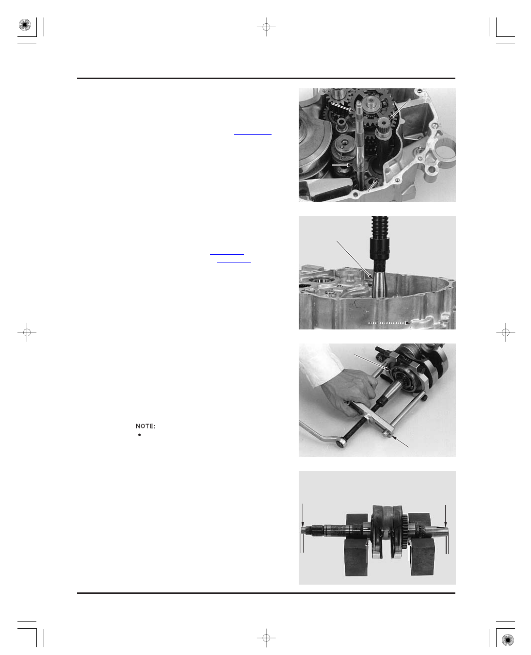
INSPECTION
CRANKCASE/TRANSMISSION/CRANKSHAFT
CRANKSHAFT
TOOL:
Universal bearing puller
SERVICE LIMIT:
11-10
CRANKSHAFT/BALANCER
Install the output shaft into the crankcase with the
washer.
Install the sub-gearshift spindle and the washer.
Assemble the crankcase halves (page 11-16).
Set the crankshaft as shown and measure the
runout using a dial indicator.
0.05 mm (0.002 in)
07631-0010000 or
equivalent
commercially
available in U.S.A.
Always replace the rear crankshaft bearing with a
new one when the crankshaft is removed.
Separate the crankcase (page 11-3).
Remove the transmission (page 11-4).
Remove the crankshaft and balancer from the rear
crankcase using a hydraulic press.
Be sure to hold the crankshaft and balancer while
pressing them out of the crankcase.
If the rear crankshaft bearing is left on the
crankshaft, remove it using the bearing puller with
a suitable protector.
H
H
o
o
l
l
d
d
B
B
E
E
A
A
R
R
I
I
N
N
G
G
P
P
U
U
L
L
L
L
E
E
R
R
B
B
A
A
L
L
A
A
N
N
C
C
E
E
R
R
C
C
R
R
A
A
N
N
K
K
S
S
H
H
A
A
F
F
T
T
W
W
A
A
S
S
H
H
E
E
R
R
O
O
U
U
T
T
P
P
U
U
T
T
S
S
H
H
A
A
F
F
T
T
W
W
A
A
S
S
H
H
E
E
R
R
H
H
o
o
l
l
d
d
G
G
E
E
A
A
R
R
S
S
H
H
I
I
F
F
T
T
S
S
P
P
I
I
N
N
D
D
L
L
E
E
B
B
E
E
A
A
R
R
I
I
N
N
G
G
6
6
m
m
m
m
6
6
m
m
m
m
Be caref ul not to
damage the
crankcase mating
surf ace and
crankshaf t
assembly.
03/01/08 10:10:20 61HN400F_023