ATV Honda TRX350 TM/TE, TRX350 FM/FE. Service Manual - part 13


  Index      Manuals     ATV Honda TRX350 TM/TE, TRX350 FM/FE. Service Manual


Search            copyright infringement  


Content      ..     11      12      13      14     ..


ATV Honda TRX350 TM/TE, TRX350 FM/FE. Service Manual - part 13


INSTALLATION

REMOVAL

FRONT WHEEL/SUSPENSION/STEERING

12-8

TORQUE:

TIRES

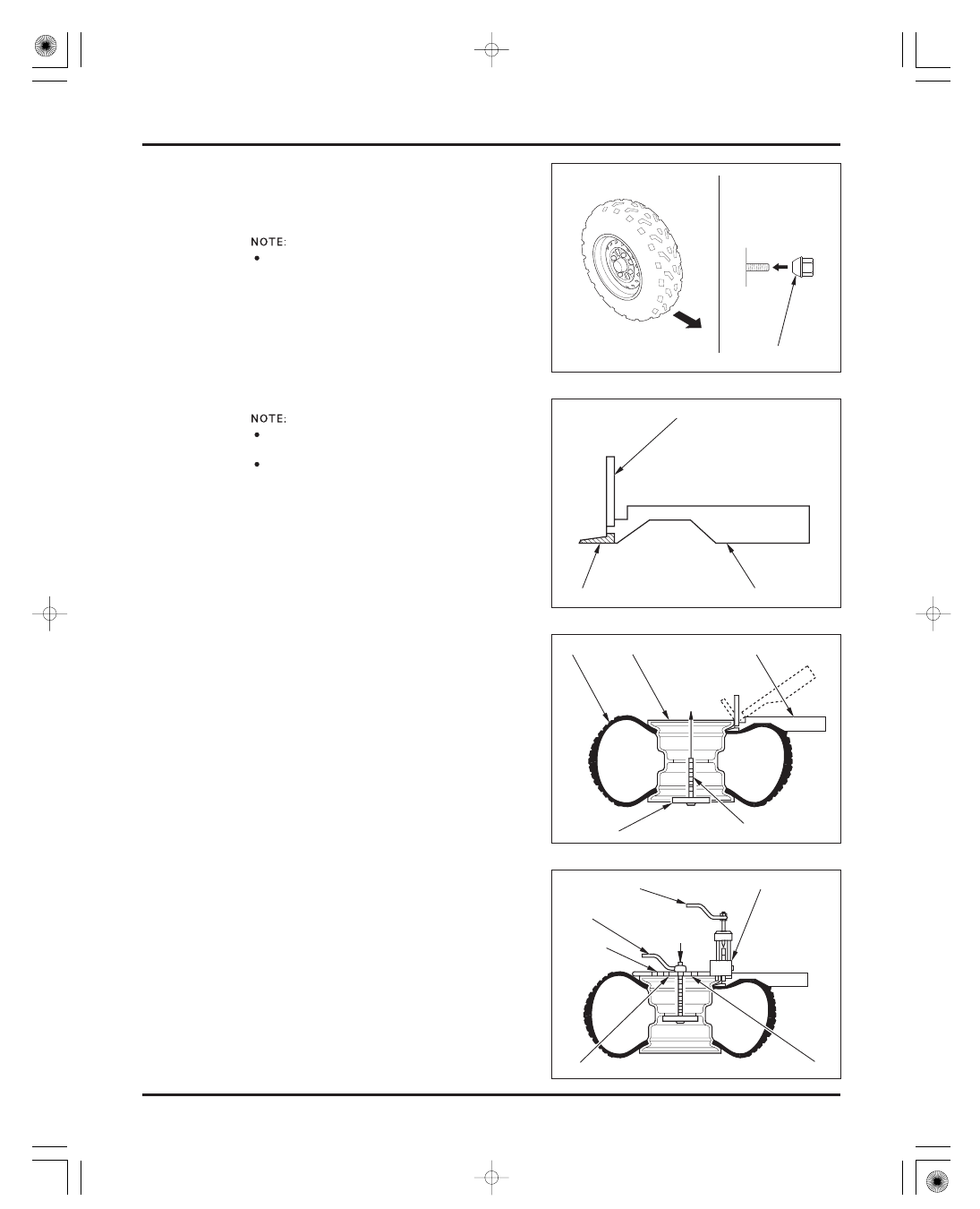
Install the wheel with the arrow mark facing in the
normal rotating direction.

Do not interchange the left and right tires.

Install the wheel nuts with the tapered side facing
inward and tighten them.

64 N·m (6.5 kgf·m , 47 lbf·ft)

Remove the core from the valve stem.

Use a pneumatic tire changer or equivalent to
remove the tire from the rim. If a tire changer is not
available, rim protectors and tire irons may be used.

Install the blade for 9/11’’ (rear) rims onto the
breaker arm assembly. Use only one of the two
white buttons.

Place the proper size adaptor onto the threaded
shaft and then put the wheel over the threaded
shaft and adaptor.

Lube the bead area with water, pressing down on
the tire sidewall/bead area in several places to
allow the water to run into and around the bead.
Also lube the area where the breaker arm will
contact the sidewall of the tire.

While holding the breaker arm assembly at an
approximate 45° position, insert the blade of the
breaker arm between the tire and rim. Push the
breaker arm inward and downward until it is in the
horizontal position with its press block in contact
with the rim.

With the breaker arm in the horizontal position,
place the breaker press head assembly over the
breaker arm press block. Make sure the press head
bolt is backed out all the way and then position the
nylon button on the press head against the inside
edge of the rim.

Insert the threaded shaft through the appropriate
hole in the breaker press head assembly and then
tighten the lever nut until both ends of the breaker
press head assembly are in firm contact with the
rim.

This service requires the Universal Bead Breaker
(GN-AH-958-BB1).
Remove and install the tire from the rim side
opposite the valve stem.

FRONT

TAPERED SIDE

PRESS BLOCK

ADAPTOR

BREAKER ARM ASSEMBLY

RIM

TIRE

PRESS HEAD BOLT

LEVER NUT

11’’ RIM

8’’ RIM

9’’ RIM

7’’ RIM

BREAKER ARM ASSEMBLY

BLADE

THREADED SHAFT

PRESS HEAD ASSEMBLY

Do not damage the

bead seating area

of the rim.

Use of an

improper size

blade may result

in damage to the

rim, tire or blade.

Use only water as

a lubricant when

removing or

mounting tires.

Soap or some

mounting

lubricants may

leave a slippery

residue which can

cause the tire to

shif t on the rim

and lose air

pressure during

riding.

03/01/08 10:25:48 61HN400G_009

-------------------------------------------------------------------------------------------------------------------------------------------------------------

TIRE REPAIR

FRONT WHEEL/SUSPENSION/STEERING

12-9

Check the tire for puncturing objects.
Chalk mark the punctured area and remove the
puncturing object.
Inspect and measure the injury.
Tire repairs for injuries lager than 15 mm (5/8 in)
should be a section repair.
Section repairs should be done by a professional
tire repair shop.
If the injury is smaller than 15 mm (5/8 in), proceed
with the repair as described here.

Install a rubber plug into the injury as follows:
Apply a cement to a plug inserting needle and work
the needle into the injury to clean and lubricate it.
Do this three times.
Do not let the cement dry.

Use the manufacturer’s instructions for the tire
repair kit you are using. If your kit does not have
instructions, use the procedures provided here.

Tighten the press head bolt until the reference
mark on the press block is aligned with the top
edge of the press head.

If the rest of the bead cannot be pushed down into
the center of the rim by hand, loosen the press
head bolt and the lever nut.
Rotate the breaker arm assembly and breaker press
head assembly 1/8 to 1/4 the circumference of the
rim.
Tighten the lever nut and then tighten the press
head bolt as described.

Repeat this procedure as necessary until the
remainder of the bead can be pushed down into the
center of the rim.

Assemble the Universal Bead Breaker on the other
side of the wheel and break the bead following the
same procedures.

Remove the tire from the rim using a tire changer
machine or tire irons and rim protectors.

Remove the tire from the side of the rim that has
the smallest shoulder area to simplify removal.

REFERENCE MARK

RIM BEAD BLOCKS

TOP EDGE OF
PRESS HEAD

03/01/08 10:25:56 61HN400G_010

-------------------------------------------------------------------------------------------------------------------------------------------------------------

ASSEMBLY

FRONT WHEEL/SUSPENSION/STEERING

12-10

Insert and center a rubber plug through the eye of
the inserting needle.

Apply cement to the rubber plug.
Push the inserting needle with plug into the injury
until the plug is slightly above the tire.
Twist the needle and remove it from the tire; the
plug will stay in the tire.

Trim the plug 6 mm (1/4 in) above the tire surface.
Repeat the above procedure if the puncture is large.
Do not use more than two plugs per injury.

Allow the repair to dry. Drying time will vary with
air temperature. Refer to the tire repair kit
manufacturer’s recommendations.

Inflate the tire and test the seal by dabbing a small
amount of cement around the plug. Escaping air
will cause a bubble in the cement. If there is
leakage, remove the tire (page 12-7) and apply a
cold patch to the inside of the tire as described.
If a plug has been inserted, trim it even with the
inner tire surface.

Temporarily place a rubber patch that is at least
twice the size of the puncture over the injury. Make
a mark around the patch, slightly larger than the
patch itself.
Rough the area marked inside the tire with a tire
buffer or a wire brush. Clean the rubber dust from
the buffed area.

Apply cement over the area marked and allow it to
dry until tacky.
Do not touch the cement with dirty or greasy hands.
Remove the lining from the patch and center it over
the injury.
Press the patch against the injury using a special
roller.

Install the tire onto the rim, where the rim shoulder
width is the narrowest, to simplify installation.

Clean the rim bead seat and flanges.
Apply clean water to the rim flanges, bead seat and
base.

Install the valve core in the valve stem.
Install the tire with the arrow mark facing in the
normal rotating direction.
Inflate the tire to seat the tire bead.

Deflate the tire. Wait 1 hour and inflate the tire to
the specified pressure (page 3-18).

Check for air leaks and install the valve cap.

Be caref ul not to

push the plug all

the way into the

tire to prevent it

f rom f alling inside.

Soap or some

mounting

lubricants may

leave a slippery

residue which can

cause the tire to

shif t on the rim

and lose air

pressure during

riding.

Use only water as

a lubricant

removing or

mounting tires.

03/01/08 10:26:03 61HN400G_011

-------------------------------------------------------------------------------------------------------------------------------------------------------------


REMOVAL

FRONT WHEEL/SUSPENSION/STEERING

12-11

WHEEL HUB AND KNUCKLE

Remove the wheel (page 12-7).

Remove the following:

cotter pin
hub nut
brake drum/hub

For waterproof seal inspection, see section 14.

Support the brake panel so that it does not hang
from the brake hose.

Remove the cotter pin from the tie-rod ball joint
stud.
Remove the joint nut by holding the joint stud flat
surfaces.

For tie-rod service, see page 12-19.

Remove the cotter pins from the ball joint studs.
Loosen the joint nuts, but do not remove them yet.

O-ring (TM/TE model only)
brake panel bolts

C

C

O

O

T

T

T

T

E

E

R

R

P

P

I

I

N

N

A

A

N

N

D

D

N

N

U

U

T

T

B

B

R

R

A

A

K

K

E

E

D

D

R

R

U

U

M

M

/

/

H

H

U

U

B

B

B

B

R

R

A

A

K

K

E

E

P

P

A

A

N

N

E

E

L

L

O

O

-

-

R

R

I

I

N

N

G

G

C

C

O

O

T

T

T

T

E

E

R

R

P

P

I

I

N

N

N

N

U

U

T

T

T

T

I

I

E

E

-

-

R

R

O

O

D

D

C

C

O

O

T

T

T

T

E

E

R

R

P

P

I

I

N

N

S

S

A

A

N

N

D

D

N

N

U

U

T

T

S

S

Do not get grease

on the brake shoes

or stopping power

will be reduced.

Do not twist the

brake hose.

03/01/08 10:26:14 61HN400G_012

-------------------------------------------------------------------------------------------------------------------------------------------------------------

TOOL:
Ball joint remover, 28 mm

FRONT WHEEL/SUSPENSION/STEERING

12-12

Release the ball joints, using the special tool
according to the following instructions.

Apply grease to the ball joint remover at the point
shown.
This will ease installation of the tool and prevent
damage to the pressure bolt threads.

Insert the jaws carefully, making sure that you do
not damage the ball joint boot.
Adjust the jaw spacing by turning the pressure bolt.

Once the tool is in place, turn the adjusting bolt as
necessary to make the jaws parallel.
Then hand-tighten the pressure bolt and recheck
the jaws to make sure they are still parallel.

Tighten the pressure bolt with a wrench until the
ball joint stud pops loose.

Remove the knuckle from the upper and lower
arms by loosening the joint nuts.

Remove the O-ring from the knuckle.

For suspension arm service, see page 12-16.

07MAC-SL00200

Apply grease here

PRESSURE BOLT

ADJUSTING BOLT

O

O

-

-

R

R

I

I

N

N

G

G

PRESSURE BOLT

R

R

E

E

M

M

O

O

V

V

E

E

R

R

If necessary, apply

penetrating type

lubricant to loosen

the ball joint.

03/01/08 10:26:22 61HN400G_013

-------------------------------------------------------------------------------------------------------------------------------------------------------------


INSPECTION

BEARING REPLACEMENT

FRONT WHEEL/SUSPENSION/STEERING

HUB

TOOLS:
Bearing remover set, 20 mm

Bearing remover, 20 mm
Remover handle
Sliding weight

12-13

Remove the side collar and dust seal.

Remove the hub bearing with the special tools.
Remove the distance collar and drive out the other
bearing.

07936-3710001
not available in
U.S.A.
07936-3710600
07936-3710100
07741-0010201 or
07936-371020A or
07936-3710200

Turn the inner race of each bearing in the brake
drum/hub (TM/TE models) and knuckle (FM/FE
models) with your finger. The bearings should turn
smoothly and quietly. Also check that the bearing
outer race fits tightly in the hub or knuckle.

Inspect the knuckle for damage or cracks.

Inspect the ball joint boot for tears or other damage
by moving the ball joint stud.
It should move freely and smoothly.

For ball joint replacement, see page 12-17.

B

B

E

E

A

A

R

R

I

I

N

N

G

G

B

B

E

E

A

A

R

R

I

I

N

N

G

G

D

D

U

U

S

S

T

T

S

S

E

E

A

A

L

L

B

B

O

O

O

O

T

T

C

C

O

O

L

L

L

L

A

A

R

R

B

B

E

E

A

A

R

R

I

I

N

N

G

G

R

R

E

E

M

M

O

O

V

V

E

E

R

R

Replace the

bearings in pairs.

T M/ T E model

only:

03/01/08 10:26:33 61HN400G_014

-------------------------------------------------------------------------------------------------------------------------------------------------------------

×

KNUCKLE

TOOLS:
Driver
Attachment
Pilot, 30 mm

TOOLS:
Driver
Attachment, 42

47 mm

Pilot, 20 mm

FRONT WHEEL/SUSPENSION/STEERING

12-14

Drive in a new inner bearing (brake drum side)
squarely with the marking side facing up until it is
fully seated.
Install the distance collar.
Drive in a new outer bearing squarely with the
marking side facing up until it is fully seated.

07749-0010000
07746-0010300
07746-0040500

Apply grease to a new dust seal lips.
Install the dust seal until they are flush with the hub
surface.

Install the side collar.

Remove the dust seals and the snap ring.
Drive the bearing out of the knuckle.

Pack the cavities of a new bearing with grease.
Drive in the bearing squarely with the marking side
facing up until it is fully seated.

07749-0010000
07945-3330300
07746-0040700

Install the snap ring into the knuckle groove with
the chamfered edge facing in.

P

P

I

I

L

L

O

O

T

T

A

A

T

T

T

T

A

A

C

C

H

H

M

M

E

E

N

N

T

T

D

D

R

R

I

I

V

V

E

E

R

R

P

P

I

I

L

L

O

O

T

T

C

C

O

O

L

L

L

L

A

A

R

R

D

D

U

U

S

S

T

T

S

S

E

E

A

A

L

L

B

B

E

E

A

A

R

R

I

I

N

N

G

G

D

D

R

R

I

I

V

V

E

E

R

R

A

A

T

T

T

T

A

A

C

C

H

H

M

M

E

E

N

N

T

T

D

D

U

U

S

S

T

T

S

S

E

E

A

A

L

L

S

S

S

S

N

N

A

A

P

P

R

R

I

I

N

N

G

G

Support the center

boss of the hub to

avoid damaging

the waterproof

seal.

F M/ F E model

only:

03/01/08 10:26:46 61HN400G_015

-------------------------------------------------------------------------------------------------------------------------------------------------------------

INSTALLATION

FRONT WHEEL/SUSPENSION/STEERING

TOOLS:
Driver
Oil seal driver

TORQUE:

TORQUE:

12-15

Apply grease to a new outer dust seal lips and
install it using the same tools until it is flush with
the knuckle end.

Apply grease to a new inner dust seal lips and
install it until it is fully seated being careful not to
damage the lips.

07749-0010000
07JAD-PH80101

Tighten the tie-rod joint nut.

Install new cotter pins.

Coat a new O-ring with grease and install it onto
the knuckle.

29 N·m (3.0 kgf·m , 22 lbf·ft)

54 N·m (5.5 kgf·m , 40 lbf·ft)

Install the knuckle onto the drive shaft (FM/FE only)
and the lower and upper arms with the joint nuts.
Connect the tie-rod into the knuckle with a new
joint nut.

Tighten each arm joint nut to the specified torque
and further tighten until their grooves align with
the cotter pin hole.

N

N

U

U

T

T

O

O

-

-

R

R

I

I

N

N

G

G

O

O

I

I

L

L

S

S

E

E

A

A

L

L

D

D

R

R

I

I

V

V

E

E

R

R

I

I

N

N

N

N

E

E

R

R

D

D

U

U

S

S

T

T

S

S

E

E

A

A

L

L

O

O

U

U

T

T

E

E

R

R

D

D

U

U

S

S

T

T

S

S

E

E

A

A

L

L

D

D

R

R

I

I

V

V

E

E

R

R

K

K

N

N

U

U

C

C

K

K

L

L

E

E

T

T

I

I

E

E

-

-

R

R

O

O

D

D

N

N

U

U

T

T

C

C

O

O

T

T

T

T

E

E

R

R

P

P

I

I

N

N

C

C

O

O

T

T

T

T

E

E

R

R

P

P

I

I

N

N

03/01/08 10:26:59 61HN400G_016

-------------------------------------------------------------------------------------------------------------------------------------------------------------


REMOVAL

INSPECTION

FRONT WHEEL/SUSPENSION/STEERING

12-16

TORQUE:

SUSPENSION ARM

Install the brake panel onto the knuckle and tighten
the four bolts.

Coat a new O-ring with grease and install it into the
axle groove.

Install a new cotter pin.

Install the wheel (page 12-8).

Apply molybdenum disulfide grease to the drive
shaft spline.

Apply grease to the hub nut threads and seating
surface.
Install the brake drum/hub with the hub nut.
Tighten the nut to the specified torque and further
tighten until its grooves align with the cotter pin
hole.

78 N·m (8.0 kgf·m , 58 lbf·ft)

Remove the knuckle (page 12-11).

Remove the following:

Make sure that the waterproof seal on the brake
drum is packed with the multi-purpose grease
(NLGI

3) (page 14-9).

lower arm guard if necessary (FM/FE models)
pivot nuts, bolts and lower arm
two clamp bolts from upper arm
shock absorber lower mounting nut and bolt
pivot nuts, bolts (remove front side first) and
upper arm

Check the pivot bushings for wear or damage.
Inspect the ball joint boot for tears or other damage
by moving the ball joint studs.
It should move freely and smoothly.

B

B

R

R

A

A

K

K

E

E

P

P

A

A

N

N

E

E

L

L

J

J

O

O

I

I

N

N

T

T

B

B

O

O

O

O

T

T

L

L

O

O

W

W

E

E

R

R

A

A

R

R

M

M

C

C

L

L

A

A

M

M

P

P

S

S

S

S

H

H

O

O

C

C

K

K

A

A

B

B

S

S

O

O

R

R

B

B

E

E

R

R

B

B

R

R

A

A

K

K

E

E

D

D

R

R

U

U

M

M

/

/

H

H

U

U

B

B

N

N

U

U

T

T

O

O

-

-

R

R

I

I

N

N

G

G

C

C

O

O

T

T

T

T

E

E

R

R

P

P

I

I

N

N

U

U

P

P

P

P

E

E

R

R

A

A

R

R

M

M

B

B

U

U

S

S

H

H

I

I

N

N

G

G

S

S

LOWER ARM
GUARD

T M/ T E model

only:

F M/ F E model

only:

Do not get grease

onto the brake

drum and shoes.

03/01/08 10:27:14 61HN400G_017

-------------------------------------------------------------------------------------------------------------------------------------------------------------

×

BALL JOINT REPLACEMENT

FRONT WHEEL/SUSPENSION/STEERING

UPPER ARM

KNUCKLE

TOOLS:
Ball joint remover/installer
Attachment, 28

30 mm

TOOLS:
Ball joint remover/installer
Attachment, 20 mm I.D.

12-17

Remove the snap ring from the ball joint.

Set the upper arm and special tools with ‘‘A’’ mark
side of the remover/installer facing to the ball joint
as shown.
Press the ball joint out of the upper arm.

07WMF-HN00100
07946-1870100

Set the upper arm and special tools with ‘‘B’’ mark
side of the remover/installer facing to the ball joint
as shown.
Press the ball joint into the upper arm until it is fully
seated.

If you feel strong resistance when lowering the
press, stop. Reset the attachment of the tool so that
the ball joint head can go into the hollow of the
attachment and try again.

Install the snap ring with the chamfered edge
facing in.

Remove the snap ring and the inner dust seal (FM/
FE model only).

07WMF-HN00100
07746-0020400

S

S

N

N

A

A

P

P

R

R

I

I

N

N

G

G

A

A

B

B

R

R

E

E

M

M

O

O

V

V

E

E

R

R

/

/

I

I

N

N

S

S

T

T

A

A

L

L

L

L

E

E

R

R

A

A

T

T

T

T

A

A

C

C

H

H

M

M

E

E

N

N

T

T

A

A

T

T

T

T

A

A

C

C

H

H

M

M

E

E

N

N

T

T

R

R

E

E

M

M

O

O

V

V

E

E

R

R

/

/

I

I

N

N

S

S

T

T

A

A

L

L

L

L

E

E

R

R

I

I

N

N

N

N

E

E

R

R

D

D

U

U

S

S

T

T

S

S

E

E

A

A

L

L

S

S

N

N

A

A

P

P

R

R

I

I

N

N

G

G

03/01/08 10:27:30 61HN400G_018

-------------------------------------------------------------------------------------------------------------------------------------------------------------


×

INSTALLATION

FRONT WHEEL/SUSPENSION/STEERING

TOOLS:
Ball joint remover/installer
Attachment, 28

30 mm

TOOLS:
Ball joint remover/installer
Attachment, 15 mm I.D.

TORQUE:

Upper/Lower arm:
Shock absorber:

12-18

Set the knuckle and special tools with ‘‘A’’ mark
side of the remover/installer facing to the ball joint,
in a vise as shown.
Press the ball joint out of the knuckle.

07JMF-HC50110
07946-1870100

Install the following:

upper arm onto frame and shock absorber with
pivot bolts (from front side)
new pivot nuts

lower arm with pivot bolts (from front side)
new pivot nuts

Install the brake hose and breather tube onto the
upper arm and tighten the two clamp bolts.

Install the knuckle (page 12-15).

44 N·m (4.5 kgf·m , 33 lbf·ft)

30 N·m (3.1 kgf·m , 22 lbf·ft)

Set the knuckle and special tools with ‘‘B’’ mark
side of the remover/installer facing to the ball joint
in a vise as shown.
Press the ball joint into the knuckle until it is fully
seated.

07JMF-HC50110
07746-0020200

If you feel strong resistance when lowering the
press, stop. Reset the attachment of the tool so that
the ball joint head can go into the hollow of the
attachment and try again.

Install the snap ring with the chamfered edge
facing in.
Install the dust seal (page 12-15).

R

R

E

E

M

M

O

O

V

V

E

E

R

R

/

/

I

I

N

N

S

S

T

T

A

A

L

L

L

L

E

E

R

R

R

R

E

E

M

M

O

O

V

V

E

E

R

R

/

/

I

I

N

N

S

S

T

T

A

A

L

L

L

L

E

E

R

R

A

A

B

B

O

O

L

L

T

T

S

S

A

A

N

N

D

D

N

N

U

U

T

T

S

S

U

U

P

P

P

P

E

E

R

R

A

A

R

R

M

M

B

B

A

A

T

T

T

T

A

A

C

C

H

H

M

M

E

E

N

N

T

T

A

A

T

T

T

T

A

A

C

C

H

H

M

M

E

E

N

N

T

T

B

B

O

O

L

L

T

T

S

S

A

A

N

N

D

D

N

N

U

U

T

T

S

S

C

C

L

L

A

A

M

M

P

P

S

S

H

H

O

O

S

S

E

E

A

A

N

N

D

D

T

T

U

U

B

B

E

E

L

L

O

O

W

W

E

E

R

R

A

A

R

R

M

M

03/01/08 10:27:45 61HN400G_019

-------------------------------------------------------------------------------------------------------------------------------------------------------------


REMOVAL

FRONT WHEEL/SUSPENSION/STEERING

12-19

STEERING SHAFT AND TIE-ROD

Remove the following:

Remove the following:

front fender (page 2-7)
inner fenders (page 2-9)
handlebar cover (U.S.A. TM/FM models)/meter
cover and combination meter (Except U.S.A. TM/
FM) (page 12-3)

wire harness from harness clip (by releasing clip)
cables from guide
brake hose from clamps

lower holder nuts and washers
handlebar assembly from steering shaft

holder bolts
steering shaft holders

cotter pins (from knuckle and steering shaft ball
joint studs)
joint nuts (by holding joint stud flat surfaces)
tie-rods (from steering shaft and knuckles)

N

N

U

U

T

T

S

S

C

C

L

L

I

I

P

P

C

C

L

L

A

A

M

M

P

P

S

S

G

G

U

U

I

I

D

D

E

E

H

H

A

A

N

N

D

D

L

L

E

E

B

B

A

A

R

R

N

N

U

U

T

T

S

S

A

A

N

N

D

D

W

W

A

A

S

S

H

H

E

E

R

R

S

S

H

H

O

O

L

L

D

D

E

E

R

R

S

S

C

C

O

O

T

T

T

T

E

E

R

R

P

P

I

I

N

N

S

S

T

T

I

I

E

E

-

-

R

R

O

O

D

D

B

B

O

O

L

L

T

T

S

S

W hen removing

the tie-rod only, it

can be removed

without removing

the f ront f ender.

Do not twist or

bend the brake

hose and pipe.

03/01/08 10:27:57 61HN400G_020

-------------------------------------------------------------------------------------------------------------------------------------------------------------


INSPECTION

FRONT WHEEL/SUSPENSION/STEERING

12-20

cotter pin (from steering shaft end)
shaft end nut and washer
shaft arm
steering shaft

Inspect the tie-rod for distortion or damage.
Inspect the ball joint boots for tears or other
damage by moving the ball joint studs.
They should move freely and smoothly.

Check the steering shaft bushing for wear or
damage.

Check the steering shaft for distortion or damage.

S

S

T

T

E

E

E

E

R

R

I

I

N

N

G

G

S

S

H

H

A

A

F

F

T

T

C

C

O

O

T

T

T

T

E

E

R

R

P

P

I

I

N

N

N

N

U

U

T

T

A

A

N

N

D

D

W

W

A

A

S

S

H

H

E

E

R

R

A

A

R

R

M

M

03/01/08 10:28:06 61HN400G_021

-------------------------------------------------------------------------------------------------------------------------------------------------------------

×

×

BEARING REPLACEMENT

TIE-ROD ASSEMBLY

FRONT WHEEL/SUSPENSION/STEERING

TOOLS:
Driver
Attachment, 32

35 mm

TOOLS:
Driver
Attachment, 42

47 mm

Pilot, 20 mm

12-21

Turn the inner race of the bearing with your finger.
The bearing should turn smoothly and quietly. Also
check that the bearing outer race fits tightly in the
frame.

Remove the upper and lower dust seals.
Remove the snap ring.

Drive the steering shaft bearing out of the frame
from below.

07749-0010000
07746-0010100

Drive in a new bearing squarely with the marked
side facing up until it is fully seated.

07949-3710001
07746-0010300
07746-0040500

Install the snap ring into the groove properly with
the chamfered edge facing up.

Coat new dust seals with grease and install them
(the upper seal is flush with the frame edge and the
lower seal is fully seated onto the bearing).

When the tie-rod ball joints will be replaced, install
the ball joints and lock nuts as shown.

Adjust the tie-rod length so that the distance
between each lock nut and thread end is 4.5 mm
(TM/TE models)/8.75 mm (FM/FE models). (A
difference between both ends distances is 3 mm
max.)

Temporarily tighten the lock nuts while the ball
joint positions are 180° from each other.

S

S

N

N

A

A

P

P

R

R

I

I

N

N

G

G

D

D

U

U

S

S

T

T

S

S

E

E

A

A

L

L

S

S

B

B

E

E

A

A

R

R

I

I

N

N

G

G

G

G

o

o

l

l

d

d

S

S

i

i

l

l

v

v

e

e

r

r

(

(

l

l

e

e

f

f

t

t

h

h

a

a

n

n

d

d

t

t

h

h

r

r

e

e

a

a

d

d

s

s

)

)

F

F

L

L

A

A

T

T

(

(

w

w

r

r

e

e

n

n

c

c

h

h

h

h

o

o

l

l

d

d

i

i

n

n

g

g

p

p

o

o

s

s

i

i

t

t

i

i

o

o

n

n

)

)

T

T

M

M

/

/

T

T

E

E

:

:

4

4

.

.

5

5

m

m

m

m

(

(

0

0

.

.

2

2

i

i

n

n

)

)

F

F

M

M

/

/

F

F

E

E

:

:

8

8

.

.

7

7

5

5

m

m

m

m

(

(

0

0

.

.

3

3

i

i

n

n

)

)

4

4

.

.

5

5

m

m

m

m

(

(

0

0

.

.

2

2

i

i

n

n

)

)

8

8

.

.

7

7

5

5

m

m

m

m

(

(

0

0

.

.

3

3

i

i

n

n

)

)

T ighten these nuts

af ter installing the

tie-rod into the

knuckle and

steering shaf t.

03/01/08 10:28:20 61HN400G_022

-------------------------------------------------------------------------------------------------------------------------------------------------------------

INSTALLATION

FRONT WHEEL/SUSPENSION/STEERING

12-22

TORQUE:

TORQUE:

TORQUE:

32 N·m (3.3 kgf·m , 24 lbf·ft)

54 N·m (5.5 kgf·m , 40 lbf·ft)

Install the bushing ring onto the shaft bushing.
Apply grease to the shaft bushing inner surface.

Install the shaft bushing onto the steering shaft
with the ‘‘UP’’ mark facing up.
Install the steering shaft into the shaft bearing.

Install the shaft holders and bolts with the hose
clamp on the front holder facing the right side.
Tighten the holder bolts.

Apply grease to the end nut threads and seating
surface.
Apply molybdenum disulfide grease to the steering
shaft spline.

Install the shaft arm over the steering shaft by
aligning the wide tooth with the wide groove.
Install the washer and end nut, and tighten the nut
to the specified torque.

108 N·m (11.0 kgf·m , 80 lbf·ft)

Install a new cotter pin.

Install the tie-rod into the steering shaft and knuckle
with the flat area (wrench holding point) toward the
knuckle.
Install new joint nuts and tighten them by holding
the joint stud flat surfaces.

J

J

O

O

I

I

N

N

T

T

N

N

U

U

T

T

S

S

U

U

P

P

M

M

A

A

R

R

K

K

B

B

U

U

S

S

H

H

I

I

N

N

G

G

C

C

L

L

A

A

M

M

P

P

H

H

O

O

L

L

D

D

E

E

R

R

S

S

B

B

O

O

L

L

T

T

S

S

W

W

A

A

S

S

H

H

E

E

R

R

A

A

N

N

D

D

N

N

U

U

T

T

A

A

R

R

M

M

A

A

l

l

i

i

g

g

n

n

C

C

O

O

T

T

T

T

E

E

R

R

P

P

I

I

N

N

F

F

L

L

A

A

T

T

T

T

I

I

E

E

-

-

R

R

O

O

D

D

J

J

O

O

I

I

N

N

T

T

N

N

U

U

T

T

R

R

I

I

N

N

G

G

S

S

T

T

E

E

E

E

R

R

I

I

N

N

G

G

S

S

H

H

A

A

F

F

T

T

03/01/08 10:28:35 61HN400G_023

-------------------------------------------------------------------------------------------------------------------------------------------------------------


REMOVAL

FRONT WHEEL/SUSPENSION/STEERING

12-23

FRONT SHOCK ABSORBER

TORQUE:

TORQUE:

Install new cotter pins into the ball joint studs.

Install the handlebar assembly onto the steering
shaft with new lower holder nuts and washers.
Tighten the nuts.

Support the vehicle with a support block to raise
the front wheels off the ground.

Support the suspension arm or front wheel, and
remove the mounting nuts, bolts and shock
absorber.

39 N·m (4.0 kgf·m , 29 lbf·ft)

54 N·m (5.5 kgf·m , 40 lbf·ft)

If the tie-rod ball joints were replaced, tighten the
lock nuts as follows:
Rotate both ball joints with the tie-rod axis until
they stop against the ball joint studs. Hold them in
that position and tighten the ball joint lock nuts.

Install the brake hose into the clamps to secure it.
Install the cables into the cable guide.
Secure the wires with the clip.

Adjust the toe (page 3-19).

Install the following:

inner fenders (page 2-9)
front fender (page 2-7)
handlebar cover (U.S.A. TM/FM models)/meter
cover and combination meter (Except U.S.A. TM/
FM) (page 12-3)

C

C

L

L

A

A

M

M

P

P

S

S

C

C

O

O

T

T

T

T

E

E

R

R

P

P

I

I

N

N

C

C

O

O

T

T

T

T

E

E

R

R

P

P

I

I

N

N

S

S

G

G

U

U

I

I

D

D

E

E

C

C

L

L

I

I

P

P

W

W

A

A

S

S

H

H

E

E

R

R

S

S

A

A

N

N

D

D

N

N

U

U

T

T

S

S

S

S

H

H

O

O

C

C

K

K

A

A

B

B

S

S

O

O

R

R

B

B

E

E

R

R

L

L

O

O

C

C

K

K

N

N

U

U

T

T

S

S

H

H

A

A

N

N

D

D

L

L

E

E

B

B

A

A

R

R

Do not twist or

bend the brake

hose and pipe.

Route the wire and

cable properly

( page 1-22).

03/01/08 10:28:47 61HN400G_024

-------------------------------------------------------------------------------------------------------------------------------------------------------------


Content      ..     11      12      13      14     ..