Suzuki GSX-R1000. Service Manual - part 33


  Index      Manuals     Suzuki GSX-R1000. Service Manual


Search            copyright infringement  


Content      ..     31      32      33      34     ..


Suzuki GSX-R1000. Service Manual - part 33


4B-4 Front Brakes: 

Disassembly

1) Remove the brake pads (1) and spring from the 

caliper by removing the pad mounting pins.

2) Place a rag over the pistons to prevent them from 

popping out and then force out the pistons using 
compressed air.

CAUTION

!


Do not use high pressure air to prevent 
piston damage.


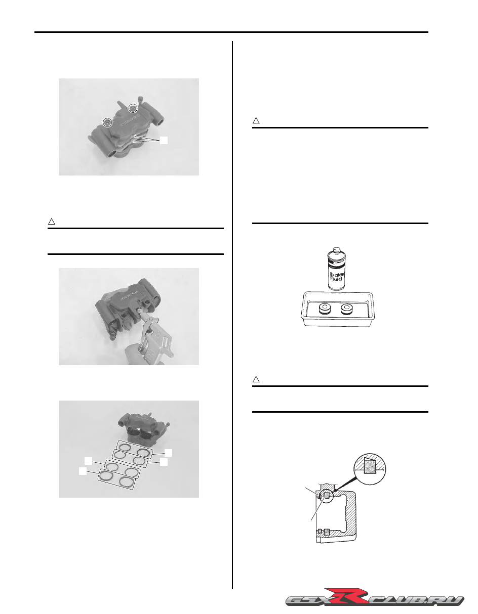
3) Remove the dust seals (2) and piston seals (3) from 

both sides of the caliper.

Assembly

Assemble the caliper in the reverse order of 
disassembly. Pay attention to the following points:

• Wash the caliper bores and pistons with specified 

brake fluid. Particularly wash the dust seal grooves 
and piston seal grooves.

BF:  Brake fluid  (DOT 4)

CAUTION

!


• Wash the caliper components with fresh 

brake fluid before reassembly. Never use 
cleaning solvent or gasoline to wash them.

• Do not wipe the brake fluid off after 

washing the components.

• When washing the components, use the 

specified brake fluid. Never use different 
types of fluid or cleaning solvent such as 
gasoline, kerosine or the others.


• Apply the brake fluid to piston seals (1) and dust seals 

(2).

CAUTION

!


Replace the piston seals (1) and dust seals 
(2) with new ones.


BF:  Brake fluid  (DOT 4)

• Install the piston seals as shown in the figure.

1

I947H1420005-01

I947H1420006-01

2

3

2

3

I947H1420007-01

I649G1420012-02

1

2

I649G1420013-02

-------------------------------------------------------------------------------------------------------------------------------------------------------------

Front Brakes:  4B-5

• When installing the spring to the caliper, bring its 

wider pawl “A” facing top side.

• Install the brake pads and temporarily tighten the pad 

mounting pins (3).

Front Brake Caliper Parts Inspection

B947H14206006

Refer to “Front Brake Caliper Disassembly and 
Assembly” (Page 4B-3)
.

Brake Caliper Cylinder

Inspect the brake caliper cylinder wall for nicks, 
scratches or other damage. If any damage is found, 
replace the caliper with a new one.

Brake Caliper Piston

Inspect the surface of brake caliper pistons for any 
scratches or other damage. If any damage is found, 
replace the pistons with a new set.

Brake Pad Mounting Pin

Inspect the brake pad mounting pins for wear and other 
damage. If any damage is found, replace the mounting 
pins with new ones.

Brake Pad Spring

Inspect the brake pad spring for damage and excessive 
bend. If any damage is found, replace it with a new one.

“A”: Wider pawl

“B”: Top side

“A”

“B”

I947H1420009-01

3

I947H1420010-01

I947H1420011-01

I947H1420012-01

I947H1420013-01

I947H1420014-01

-------------------------------------------------------------------------------------------------------------------------------------------------------------

4B-6 Front Brakes: 

Front Brake Disc Removal and Installation

B947H14206007

Removal

1) Remove the front wheel assembly. Refer to “Front 

Wheel Assembly Removal and Installation” in 
Section 2D (Page 2D-4).

2) Remove the front brake disc.

Installation

Install the front brake disc in the reverse order of 
removal. Pay attention to the following points:

• Make sure that the brake disc is clean and free of any 

grease.

• Apply thread lock to the brake disc bolts (1) and 

tighten them to the specified torque.

:  Thread lock cement 99000–32130 

(THREAD LOCK CEMENT SUPER “1360” or 
equivalent)

Tightening torque
Brake disc bolt (Front) (a):  18 N·m (1.8 kgf-m, 
13.0 lbf-ft)

Front Brake Disc Inspection

B947H14206008

Brake Disc Thickness

Check the brake disc for damage or cracks and measure 
the thickness using the micrometer.
Replace the brake disc if the thickness is less than the 
service limit or if defect is found.

Special tool

(A):  09900–20205 (Micrometer (0 – 25 mm))

Brake disc thickness
Service limit (Front): 5.0 mm (0.20 in)

Brake Disc Runout

1) Dismount the front brake caliper. Refer to “Front 

Brake Caliper Removal and Installation” (Page 4B-
3).

2) Measure the runout using the dial gauge.

Replace the disc if the runout exceeds the service 
limit.

Special tool

(A):  09900–20607 (Dial gauge)
:  09900–20701 (Dial gauge chuck)

Brake disc runout
Service limit: 0.30 mm (0.012 in)

3) Remount the front brake caliper. Refer to “Front 

Brake Caliper Removal and Installation” (Page 4B-
3).

I947H1420015-01

(a)

1

I947H1420016-02

(A)

I649G1420019-03

(A)

I649G1420020-03

-------------------------------------------------------------------------------------------------------------------------------------------------------------

Front Brakes:  4B-7

Specifications

Service Data

B947H14207001

Brake

Unit: mm (in)

Tightening Torque Specifications

B947H14207002

NOTE

The specified tightening torque is described in the following.
“Front Brake Components” (Page 4B-1)


Reference:

For the tightening torque of fastener not specified in this section, refer to “Tightening Torque List” in Section 0C 
(Page 0C-9)
.

Item

Standard

Limit

Brake disc thickness

Front

5.3 – 5.7 (0.21 – 0.22)

5.0 (0.20)

Brake disc runout

 0.30 (0.012)

Brake caliper cylinder bore

Front

Leading

30.280 – 30.330 (1.1921 – 1.1941)

Trailing

32.080 – 32.130 (1.2630 – 1.2650)

Brake caliper piston diam.

Front

Leading

30.167 – 30.200 (1.1877 – 1.1890)

Trailing

31.967 – 32.000 (1.2585 – 1.2598)

Brake fluid type

DOT 4

Fastening part

Tightening torque

Note

N

m

kgf-m

lbf-ft

Front brake caliper mounting bolt

39

3.9 28.0 

)

(Page 4B-2) / 

)

(Page 4B-3)

Front brake pad mounting pin

15

1.5 

11.0 

)

(Page 4B-2)

Brake hose union bolt

23

2.3 

16.5 

)

(Page 4B-3)

Brake disc bolt (Front)

18

1.8 

13.0 

)

(Page 4B-6)

-------------------------------------------------------------------------------------------------------------------------------------------------------------

4B-8 Front Brakes: 

Special Tools and Equipment

Recommended Service Material

B947H14208001

NOTE

Required service material is also described in the following.
“Front Brake Components” (Page 4B-1)


Special Tool

B947H14208002

Material

SUZUKI recommended product or Specification

Note

Brake fluid

DOT 4

)

(Page 4B-4) / 

)

(Page 4B-

4)

Thread lock cement

THREAD LOCK CEMENT SUPER 
“1360” or equivalent

P/No.: 99000–32130

)

(Page 4B-6)

09900–20205

09900–20607

Micrometer (0 – 25 mm)

Dial gauge

)

(Page 4B-6)

)

(Page 4B-6)

09900–20701
Dial gauge chuck

)

(Page 4B-6)

-------------------------------------------------------------------------------------------------------------------------------------------------------------

Rear Brakes:  4C-1

.Brake

Rear Brakes

Repair Instructions

Rear Brake Components

B947H14306001

7

(f)

FWD

FWD

6

8

8

5

(c)

4

3

2

(a)

(b)

(e)

(d)

1

I947H1430026-02

1. Rear brake caliper

8. Brake pad spring

: Apply silicone grease to sliding surface.

2. Piston seal

: 6 N

m (0.6 kgf-m, 4.5 lbf-ft)

: Apply thread lock to the thread part.

3. Dust seal

: 27 N

m (2.7 kgf-m, 19.5 lbf-ft)

: Apply thread lock to the thread part.

4. Piston

: 12 N

m (1.2 kgf-m, 8.5 lbf-ft)

: Apply brake fluid.

5. Rear caliper bracket

: 17 N

m (1.7 kgf-m, 12.5 lbf-ft)

: Do not reuse.

6. Rear brake pad set

: 2.5 N

m (0.25 kgf-m, 2.0 lbf-ft)

7. Rear brake disc

: 35 N

m (3.5 kgf-m, 25.5 lbf-ft)

-------------------------------------------------------------------------------------------------------------------------------------------------------------

4C-2 Rear Brakes: 

Rear Brake Pad Inspection

B947H14306002

The extent of brake pads wear can be checked by 
observing the grooved limit line “A” on the pads. When 
the wear exceeds the grooved limit line, replace the 
pads with new ones. Refer to “Rear Brake Pad 
Replacement” (Page 4C-2)
.

CAUTION

!


Replace the brake pad as a set, otherwise 
braking performance will be adversely 
affected.


Rear Brake Pad Replacement

B947H14306003

1) Remove the plug (1) and brake pad mounting pin (2).

2) Remove the brake pads (3).

CAUTION

!


Do not operate the brake pedal while the 
pads are removed.


3) Clean up the caliper, especially around the caliper 

piston.

CAUTION

!


Replace the brake pads as a set, otherwise 
braking performance will be adversely 
affected.


4) Install new brake pads.

NOTE

Make sure that the detent of the pads is 
seated onto the retainers on the caliper 
bracket.


“A”

I947H1430027-01

1

2

I947H1430001-02

3

I947H1430002-02

I947H1430003-01

-------------------------------------------------------------------------------------------------------------------------------------------------------------

Rear Brakes:  4C-3

5) Tighten the brake pad mounting pin (2) and plug (1) 

to the specified torque.

Tightening torque
Rear brake pad mounting pin (a):  17 N·m (1.7 
kgf-m, 12.5 lbf-ft)
Rear brake pad mounting pin plug (b):  2.5 N·m (
0.25 kgf-m, 2.0 lbf-ft)

NOTE

After replacing the brake pads, pump the 
brake pedal several times to check for proper 
brake operation and then check the brake 
fluid level.


Rear Brake Caliper Removal and Installation

B947H14306004

Removal

1) Remove the rear wheel. Refer to “Rear Wheel 

Assembly Removal and Installation” in Section 2D 
(Page 2D-11).

2) Drain brake fluid. Refer to “Brake Fluid 

Replacement” in Section 4A (Page 4A-6).

3) Remove the brake hose from the caliper by 

removing the union bolt (1) and catch the brake fluid 
in a suitable receptacle.

4) Remove the brake pads. Refer to “Rear Brake Pad 

Replacement” (Page 4C-2).

NOTE

Place a rag underneath the union bolt on the 
brake caliper to catch any spilt brake fluid.


5) Remove the caliper by removing the sliding pin A (2).

6) Remove the caliper bracket (3) from the swingarm.

Installation

Install the brake caliper in the reverse order of removal. 
Pay attention to the following points:

• Apply grease to the sliding pins.

:  Grease 99000–25100 (SUZUKI SILICONE 

GREASE or equivalent)

(b)

1

(a)

2

I947H1430005-02

1

I947H1430006-03

2

2

I947H1430007-03

I947H1430008-03

I947H1430009-03

-------------------------------------------------------------------------------------------------------------------------------------------------------------

4C-4 Rear Brakes: 

• Tighten the caliper sliding pin A (1) to the specified 

torque.

Tightening torque
Rear brake caliper sliding pin A (a):  27 N·m (2.7 
kgf-m, 19.5 lbf-ft)

• Fit each boot end into the sliding pin groove.

• Install the rear wheel. Refer to “Rear Wheel Assembly 

Removal and Installation” in Section 2D (Page 2D-11).

• Install the brake pads. Refer to “Rear Brake Pad 

Replacement” (Page 4C-2).

• After setting the brake hose union to the stopper, 

tighten the union bolt (2) to the specified torque.

CAUTION

!


The seal washers should be replaced with the 
new ones to prevent fluid leakage.


Tightening torque
Brake hose union bolt (b):  23 N·m (2.3 kgf-m, 16.5 
lbf-ft)

• Bleed air from the brake system after installing the 

caliper. Refer to “Air Bleeding from Brake Fluid 
Circuit” in Section 4A (Page 4A-4).

• Check the brake fluid leakage and brake operation.

WARNING

!


Brake fluid, if it leaks, will interfere with safe 
running and discolor painted surfaces. 
Check the brake hose and hose joints for 
cracks and fluid leakage.


Rear Brake Caliper Disassembly and Assembly

B947H14306005

Refer to “Rear Brake Caliper Removal and Installation” 
(Page 4C-3).

Disassembly

1) Remove the pad spring (1) and rubber boot (2) from 

the caliper.

2) Place a rag over the piston to prevent it from popping 

out and then force out the piston using compressed 
air.

CAUTION

!


Do not use high pressure air to prevent 
piston damage.


(a)

1

I947H1430010-04

I947H1430011-03

(b)

2

I947H1430012-03

1

2

I947H1430013-02

I947H1430014-01

-------------------------------------------------------------------------------------------------------------------------------------------------------------

Rear Brakes:  4C-5

3) Remove the dust seal (3) and piston seal (4).

4) Remove the rubber boot (5), pad spring (6) and 

sliding pin B (7) from the bracket.

Assembly

Assemble the caliper in the reverse order of 
disassembly. Pay attention to the following points:

• Wash the caliper bore and piston with specified brake 

fluid. Particularly wash the dust seal groove and 
piston seal groove.

BF:  Brake fluid  (DOT 4)

CAUTION

!


• Wash the caliper components with fresh 

brake fluid before reassembly. Never use 
cleaning solvent or gasoline to wash them.

• Do not wipe the brake fluid off after 

washing the components.

• When washing the components, use the 

specified brake fluid. Never use different 
types of fluid or cleaning solvent such as 
gasoline, kerosine or the others.

• Replace the piston seal and dust seal with 

new ones.


• Apply the brake fluid to dust seal (1).

BF:  Brake fluid  (DOT 4)

• Apply grease to the piston seal (2).

:  Grease 99000–25100 (SUZUKI SILICONE 

GREASE or equivalent)

• Install the piston seal (2) as shown in the figure.

• Apply thread lock to the thread part and install the 

sliding pin B (3) to the bracket.

:  Thread lock cement 99000–32110 

(THREAD LOCK CEMENT SUPER “1322” or 
equivalent) 

Tightening torque
Rear caliper sliding pin B (a):  12 N·m (1.2 kgf-m, 
8.5 lbf-ft)

3

4

I947H1430015-02

5

6

7

I947H1430028-01

I649G1430018-02

2

1

I947H1430016-04

(a)

3

I947H1430017-02

-------------------------------------------------------------------------------------------------------------------------------------------------------------

4C-6 Rear Brakes: 

• Install the rear brake caliper. Refer to “Rear Brake 

Caliper Removal and Installation” (Page 4C-3).

Rear Brake Caliper Parts Inspection

B947H14306006

Refer to “Rear Brake Caliper Disassembly and 
Assembly” (Page 4C-4).

Brake Caliper Cylinder

Inspect the brake caliper cylinder wall for nicks, 
scratches or other damage. If any damage is found, 
replace the caliper with a new one.

Brake Caliper Piston

Inspect the brake caliper piston surface for any 
scratches or other damage. If any damage is found, 
replace the piston with a new one.

Brake Caliper Sliding Pin

Inspect the brake caliper sliding pins for wear and other 
damage. If any damage is found, replace the sliding pin 
with a new one.

Boot

Inspect the boots for damage and wear. If any defects 
are found, replace it with a new one.

Brake Pad Spring

Inspect the brake pad spring for damage and excessive 
bend. If any defects are found, replace it with a new one.

Rear Brake Disc Removal and Installation

B947H14306007

Removal

1) Remove the rear wheel assembly. Refer to “Rear 

Wheel Assembly Removal and Installation” in 
Section 2D (Page 2D-11).

2) Remove the rear brake disc.

I947H1430019-01

I947H1430020-01

I947H1430021-01

I947H1430022-01

I947H1430023-01

I947H1430024-01

-------------------------------------------------------------------------------------------------------------------------------------------------------------

Rear Brakes:  4C-7

Installation

Install the rear brake disc in the reverse order of 
removal. Pay attention to the following points:

• Make sure that the brake disc is clean and free of any 

grease.

• Apply thread lock to the brake disc bolts (1) and 

tighten them to the specified torque.

:  Thread lock cement 99000–32130 

(THREAD LOCK CEMENT SUPER “1360” or 
equivalent)

Tightening torque
Brake disc bolt (Rear) (a):  35 N·m (3.5 kgf-m, 25.5 
lbf-ft)

Rear Brake Disc Inspection

B947H14306008

Brake Disc Thickness

Check the brake disc for damage or cracks and measure 
the thickness using the micrometer.
Replace the brake disc if the thickness is less than the 
service limit or if defect is found.

Special tool

(A):  09900–20205 (Micrometer (0 – 25 mm))

Brake disc thickness
Service limit (Rear): 4.5 mm (0.18 in)

Brake Disc Runout

1) Dismount the rear brake caliper. Refer to “Rear 

Brake Caliper Removal and Installation” (Page 4C-
3)
.

2) Measure the runout using the dial gauge.

Replace the disc if the runout exceeds the service 
limit.

Special tool

(A):  09900–20607 (Dial gauge)
:  09900–20701 (Dial gauge chuck)

Brake disc runout
Service limit: 0.30 mm (0.012 in)

3) Remount the rear brake caliper. Refer to “Rear 

Brake Caliper Removal and Installation” (Page 4C-
3)
.

Specifications

Service Data

B947H14307001

Brake

Unit: mm (in)

(a)

1

I947H1430025-01

(A)

I649G1430027-03

(A)

I649G1430028-03

Item

Standard

Limit

Brake disc thickness

Rear

4.8 – 5.2 (0.19 – 0.20)

 4.5 (0.18)

Brake disc runout

 0.30 (0.012)

Brake caliper cylinder bore

Rear

30.230 – 30.280 (1.1902 – 1.1921)

Brake caliper piston diam.

Rear

30.148 – 30.198 (1.1869 – 1.1889)

Brake fluid type

DOT 4

-------------------------------------------------------------------------------------------------------------------------------------------------------------

4C-8 Rear Brakes: 

Tightening Torque Specifications

B947H14307002

NOTE

The specified tightening torque is described in the following.
“Rear Brake Components” (Page 4C-1)


Reference:

For the tightening torque of fastener not specified in this section, refer to “Tightening Torque List” in Section 0C 
(Page 0C-9).

Special Tools and Equipment

Recommended Service Material

B947H14308001

NOTE

Required service material is also described in the following.
“Rear Brake Components” (Page 4C-1)


Special Tool

B947H14308002

Fastening part

Tightening torque

Note

N

m

kgf-m

lbf-ft

Rear brake pad mounting pin

17

1.7 

12.5 

)

(Page 4C-3)

Rear brake pad mounting pin plug

2.5

0.25 

2.0 

)

(Page 4C-3)

Rear brake caliper sliding pin A

27

2.7 

19.5 

)

(Page 4C-4)

Brake hose union bolt

23

2.3 

16.5 

)

(Page 4C-4)

Rear caliper sliding pin B

12

1.2 

8.5 

)

(Page 4C-5)

Brake disc bolt (Rear)

35

3.5 

25.5 

)

(Page 4C-7)

Material

SUZUKI recommended product or Specification

Note

Brake fluid

DOT 4

)

(Page 4C-5) / 

)

(Page 4C-

5)

Grease

SUZUKI SILICONE GREASE or 
equivalent

P/No.: 99000–25100

)

(Page 4C-3) / 

)

(Page 4C-

5)

Thread lock cement

THREAD LOCK CEMENT SUPER 
“1322” or equivalent

P/No.: 99000–32110

)

(Page 4C-5)

THREAD LOCK CEMENT SUPER 
“1360” or equivalent

P/No.: 99000–32130

)

(Page 4C-7)

09900–20205

09900–20607

Micrometer (0 – 25 mm)

Dial gauge

)

(Page 4C-7)

)

(Page 4C-7)

09900–20701
Dial gauge chuck

)

(Page 4C-7)

-------------------------------------------------------------------------------------------------------------------------------------------------------------

Table of Contents 5- i

5

Section 5

CONTENTS

Transmission / Transaxle

Precautions .................................................5-1

Precautions............................................................. 5-1

Precautions for Transmission / Transaxle............. 5-1

Manual Transmission.............................. 5B-1

Diagnostic Information and Procedures............5B-1

Manual Transmission Symptom Diagnosis ......... 5B-1

Repair Instructions ..............................................5B-2

Transmission Components ................................. 5B-2
Transmission Removal........................................ 5B-3
Transmission Installation .................................... 5B-5
Transmission Construction.................................. 5B-9
Countershaft Gear / Driveshaft Gear 

Disassembly and Assembly ............................ 5B-10

Transmission Related Parts Inspection............. 5B-12
Gear Position (GP) Switch Inspection............... 5B-13
Gear Position (GP) Switch Removal and 

Installation ....................................................... 5B-14

Gearshift Lever Construction ............................ 5B-15
Gearshift Lever Removal and Installation ......... 5B-15
Gearshift Lever Height Inspection and 

Adjustment ...................................................... 5B-16

Gearshift Shaft / Gearshift Cam Plate 

Components.................................................... 5B-16

Gearshift Shaft Construction ............................. 5B-17
Gearshift Shaft / Gearshift Cam Plate 

Removal and Installation................................. 5B-17

Gearshift Linkage Inspection ............................ 5B-20
Gearshift Shaft Oil Seal / Bearing Removal 

and Installation ................................................ 5B-20

Specifications .....................................................5B-21

Service Data......................................................5B-21
Tightening Torque Specifications......................5B-22

Special Tools and Equipment ...........................5B-22

Recommended Service Material .......................5B-22
Special Tool ......................................................5B-23

Clutch ....................................................... 5C-1

Precautions...........................................................5C-1

Precautions for Clutch System............................5C-1

Schematic and Routing Diagram ........................5C-1

Clutch Cable Routing Diagram............................5C-1

Diagnostic Information and Procedures ............5C-1

Clutch System Symptom Diagnosis ....................5C-1

Repair Instructions ..............................................5C-2

Clutch Lever Position Switch Inspection .............5C-2
Clutch Cable Inspection ......................................5C-2
Clutch Cable Removal and Installation ...............5C-2
Clutch Control System Components ...................5C-3
Clutch Components.............................................5C-4
Clutch Removal...................................................5C-5
Clutch Installation................................................5C-7
Clutch Parts Inspection .....................................5C-11
Clutch Lifter Pin Inspection and Adjustment .....5C-13

Specifications .....................................................5C-14

Service Data......................................................5C-14
Tightening Torque Specifications......................5C-14

Special Tools and Equipment ...........................5C-15

Recommended Service Material .......................5C-15
Special Tool ......................................................5C-15

-------------------------------------------------------------------------------------------------------------------------------------------------------------

5-1 Precautions: 

Transmission / Transaxle

Precautions

Precautions

Precautions for Transmission / Transaxle

B947H15000001

Refer to “General Precautions” in Section 00 (Page 00-1).

-------------------------------------------------------------------------------------------------------------------------------------------------------------

Manual Transmission:  5B-1

Transmission / Transaxle

Manual Transmission

Diagnostic Information and Procedures

Manual Transmission Symptom Diagnosis

B947H15204001

Condition

Possible cause

Correction / Reference Item

Engine is noisy (Noise 
seems to come from the 
transmission)

Worn or rubbing gear.

Replace.

Worn countershaft spline.

Replace countershaft.

Worn driveshaft spline.

Replace driveshaft.

Worn or rubbing primary gear.

Replace.

Worn bearing.

Replace.

Transmission will not 
shift

Broken gearshift cam.

Replace.

Distorted gearshift fork.

Replace.

Worn gearshift pawl.

Replace.

Transmission will not 
shift back

Broken return spring on shift shaft.

Replace.

Rubbing or stuck gearshift shaft.

Repair or replace.

Worn or distorted gearshift fork.

Replace.

Transmission jumps out 
of gear

Worn shifting gears on driveshaft or 
countershaft.

Replace.

Worn or distorted gearshift fork.

Replace.

Weakened gearshift stopper spring.

Replace.

Worn gearshift cam plate.

Replace.

-------------------------------------------------------------------------------------------------------------------------------------------------------------


Content      ..     31      32      33      34     ..