Suzuki GSX-R1000. Service Manual - part 31


  Index      Manuals     Suzuki GSX-R1000. Service Manual


Search            copyright infringement  


Content      ..     29      30      31      32     ..


Suzuki GSX-R1000. Service Manual - part 31


3A-6 Drive Chain / Drive Train / Drive Shaft: 

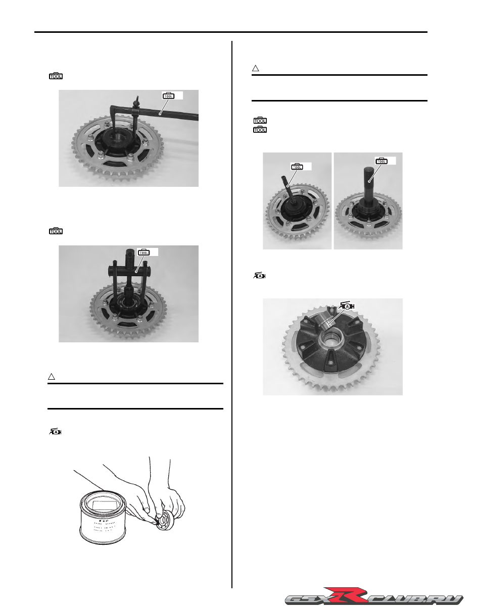
4) Remove the sprocket mounting drum dust seal with 

the special tool.

Special tool

(A):  09913–50121 (Oil seal remover)

5) Remove the sprocket mounting drum bearing with 

the special tool.

Special tool

(B):  09921–20240 (Bearing remover set)

Installation

CAUTION

!


The removed dust seal and bearing must be 
replaced with new ones.


1) Apply grease to the bearing before installing.

:  Grease 99000–25010 (SUZUKI SUPER 

GREASE “A” or equivalent)

2) Install the bearing and dust seal to the sprocket 

mounting drum with the special tools.

CAUTION

!


The sealed cover of the bearing must face 
wheel hub side.


Special tool

(A):  09924–84510 (Bearing installer set)
(B):  09913–70210 (Bearing installing set (10 

– 75 

Φ

))

3) Apply grease to the retainer.

:  Grease 99000–25010 (SUZUKI SUPER 

GREASE “A” or equivalent)

4) Install the rear sprocket mounting drum assembly to 

rear wheel hub. Refer to “Rear Sprocket / Rear 
Sprocket Mounting Drum Removal and Installation” 
(Page 3A-3)
.

5) Install the rear wheel assembly. Refer to “Rear 

Wheel Assembly Removal and Installation” in 
Section 2D (Page 2D-11).

(A)

I947H1310014-01

(B)

I947H1310015-01

I649G1310020-02

(A)

(B)

I947H1310016-01

I947H1310017-01

-------------------------------------------------------------------------------------------------------------------------------------------------------------

Drive Chain / Drive Train / Drive Shaft:  3A-7

Drive Chain Replacement

B947H13106006

Use the special tool in the following procedures, to cut 
and rejoin the drive chain.

NOTE

When using the special tool, apply a small 
quantity of grease to the threaded parts of 
the special tool.


Special tool

:  09922–22711 (Drive chain cutting and joint 

tool set)

Drive Chain Cutting

1) Set up the special tool as shown in the figure.

NOTE

The tip of pin remover (7) should be 
positioned inside “a” approximately 5 mm 
(0.2 in) from the end face of pressure bolt [A] 
(3) as shown in the figure.


2) Place the drive chain link being disjointed on the 

chain holder (8) of the tool.

3) Turn in both the adjuster bolt (6) and pressure bolt 

[A] (3) so that each of their end hole fits over the 
chain joint pin properly.

4) Tighten the pressure bolt [A] (3) with the bar.

5) Turn in the pressure bolt [B] (4) with the bar (5) and 

force out the drive chain joint pin (9).

CAUTION

!


Continue turning in the pressure bolt [B] (4) 
until the joint pin should been completely 
pushed out of the chain.


NOTE

After the joint pin (9) is removed, loosen the 
pressure bolt [B] (4) and then pressure bolt 
[A] (3).


1. Tool body

2. Grip handle

3. Pressure bolt [A]

4. Pressure bolt [B]

5. Bar

6. Adjuster bolt (With through hole)

7. Pin remover

8. Chain holder (Engraved mark 500) with reamer bolt M5 x 10

I649G1310023-02

1

2

3

4

5

6

7

8

I649G1310024-02

“a”: 5 mm (0.2 in)

7

3

“ a ”

I837H1310026-02

3

6

8

I837H1310027-02

-------------------------------------------------------------------------------------------------------------------------------------------------------------

3A-8 Drive Chain / Drive Train / Drive Shaft: 

6) Remove the joint pin (9) of the other side of joint 

plate.

CAUTION

!


Never reuse joint pins, O-rings and plates.


Drive Chain Connecting

WARNING

!


Do not use joint clip type of drive chain. The 
joint clip may have a chance to drop which 
may cause severe damage to motorcycle and 
severe injury.


Joint plate installation

1) Set up the special tool as shown in the figure.

2) Apply grease to the joint pins (8), O-rings (9) and 

plates (10).

CAUTION

!


Replace the joint pins (8), O-rings (9) and 
plates (10) with new ones.


3) Connect both ends of the drive chain with the joint 

pins (8) inserted from the wheel side “A” as installed 
on the motorcycle.

Joint set part number
DID: 27620 – 40F20

4) Apply grease on the recessed portion of the joint 

plate holder (3) and set the joint plate (10).

NOTE

When positioning the joint plate (10) on the 
tool, its stamp mark must face the joint plate 
holder (3) side.


5) Set the drive chain on the tool as illustrated and turn 

in the adjuster bolt (5) to secure the wedge holder 
and wedge pin (4).

6) Turn in the pressure bolt [A] (6) and align two joint 

pins (8) properly with the respective holes of the joint 
plate (10).

1. Tool body

2. Grip handle

3. Joint plate holder (Engraved mark “F50”)

4. Wedge holder & wedge pin

5. Adjuster bolt (Without hole)

6. Pressure bolt [A]

7. Bar

4

5

I649G1310027-02

3

4

6

7

9

I837H1310028-02

1

2

3

4

5

6

7

(F50)

I947H1310027-01

9

9

9

9

“A”

10

8

8

I837H1310029-01

3

4

5

10

I649G1310031-02

-------------------------------------------------------------------------------------------------------------------------------------------------------------

Drive Chain / Drive Train / Drive Shaft:  3A-9

7) Turn in the pressure bolt [A] (6) further using the bar 

(7) to press the joint plate over the joint pins.

8) Continue pressing the joint plate until the distance 

between the two joint plates comes to the 
specification.

Joint plate distance specification “a”
20.7 – 21.0 mm (0.81 – 0.83 in)

CAUTION

!


If pressing of the joint plate makes the 
dimension out of specification excessively, 
the work must be carried out again by using 
new joint parts.


Joint pin staking

1) Set up the special tool as shown in the figure.

NOTE

Before staking the joint pin, apply a small 
quantity of grease to the staking pin (5).


2) Stake the joint pin by turning (approximately 7/8 turn) 

the pressure bolt [A] (3) with the bar until the pin end 
diameter becomes the specified dimension.

CAUTION

!


• After joining of the chain has been 

completed, check to make sure that the 
link is smooth and no abnormal condition 
is found.

• Should any abnormal condition be found, 

reassemble the chain link using the new 
joint parts.


Pin end diameter specification “a”
DID: 5.7 – 6.0 mm (0.22 – 0.24 in)

3) Adjust the drive chain slack, after connecting it. 

Refer to “Drive Chain Inspection and Adjustment” in 
Section 0B (Page 0B-14).

1. Tool body

2. Grip handle

3. Pressure bolt [A]

4. Adjuster bolt (Without hole)

5. Staking pin (Stowed inside grip handle behind rubber cap)

6. Bar

6

7

10

8

I837H1310030-01

“a”

I649G1310033-03

1

2

3

4

5

6

I649G1310034-02

3

I649G1310035-02

“a”

I649G1310036-03

-------------------------------------------------------------------------------------------------------------------------------------------------------------

3A-10 Drive Chain / Drive Train / Drive Shaft: 

Specifications

Service Data

B947H13107001

Drive Train

Unit: mm (in) Except ratio

Tightening Torque Specifications

B947H13107002

NOTE

The specified tightening torque is described in the following.
“Drive Chain Related Components” (Page 3A-1)


Reference:

For the tightening torque of fastener not specified in this section, refer to “Tightening Torque List” in Section 0C 
(Page 0C-9).

Item

Standard

Limit

Final reduction ratio

2.470 (42/17)

Drive chain

Type

DID 50VAZ

Links

114 links

20-pitch length

319.4 (12.57)

Drive chain slack (on side-stand)

20 – 30 (0.8 – 1.2)

Gearshift lever height

65 – 75 (2.6 – 3.0)

Fastening part

Tightening torque

Note

N

m

kgf-m

lbf-ft

Engine sprocket nut

145

14.5 

105.0 

)

(Page 3A-3)

Speed sensor rotor bolt

28

2.8 

20.0 

)

(Page 3A-3)

Speed sensor mounting bolt

6.5

0.65 

4.5 

)

(Page 3A-3)

Rear sprocket nut

60

6.0 

43.0 

)

(Page 3A-4)

-------------------------------------------------------------------------------------------------------------------------------------------------------------

Drive Chain / Drive Train / Drive Shaft:  3A-11

Special Tools and Equipment

Recommended Service Material

B947H13108001

NOTE

Required service material is also described in the following.
“Drive Chain Related Components” (Page 3A-1)


Special Tool

B947H13108002

Material

SUZUKI recommended product or Specification

Note

Grease

SUZUKI SUPER GREASE “A” or 
equivalent

P/No.: 99000–25010

)

(Page 3A-3) / 

)

(Page 3A-

4) / 

)

(Page 3A-4) / 

)

(Page 3A-6) / 

)

(Page 3A-

6)

Thread lock cement

THREAD LOCK CEMENT SUPER 
“1322” or equivalent

P/No.: 99000–32110

)

(Page 3A-2)

09913–50121

09913–70210

Oil seal remover

Bearing installing set (10 – 
75 

Φ

)

)

(Page 3A-6)

)

(Page 3A-6)

09921–20240

09922–22711

Bearing remover set

Drive chain cutting and joint 
tool set

)

(Page 3A-6)

)

(Page 3A-7)

09924–84510
Bearing installer set

)

(Page 3A-6)

-------------------------------------------------------------------------------------------------------------------------------------------------------------

3A-12 Drive Chain / Drive Train / Drive Shaft: 

-------------------------------------------------------------------------------------------------------------------------------------------------------------

Table of Contents 4- i

4

Section 4

CONTENTS

Brake

Precautions .................................................4-1

Precautions............................................................. 4-1

Precautions for Brake System .............................. 4-1
Brake Fluid Information ......................................... 4-1

Brake Control System and Diagnosis ... 4A-1

Schematic and Routing Diagram........................4A-1

Front Brake Hose Routing Diagram .................... 4A-1
Rear Brake Hose Routing Diagram..................... 4A-2

Diagnostic Information and Procedures............4A-3

Brake Symptom Diagnosis.................................. 4A-3

Repair Instructions ..............................................4A-3

Brake Pedal Height Inspection and 

Adjustment ........................................................ 4A-3

Front Brake Light Switch Inspection ................... 4A-3
Rear Brake Light Switch Inspection .................... 4A-4
Rear Brake Light Switch Inspection and 

Adjustment ........................................................ 4A-4

Brake Fluid Level Check ..................................... 4A-4
Brake Hose Inspection ........................................ 4A-4
Air Bleeding from Brake Fluid Circuit .................. 4A-4
Brake Fluid Replacement.................................... 4A-6
Front Brake Hose Removal and Installation........ 4A-8
Rear Brake Hose Removal and Installation ........ 4A-8
Front Brake Master Cylinder Components.......... 4A-9
Front Brake Master Cylinder Assembly 

Removal and Installation................................. 4A-10

Front Brake Master Cylinder / Brake Lever 

Disassembly and Assembly ............................ 4A-11

Front Brake Master Cylinder Parts Inspection .. 4A-13
Rear Brake Master Cylinder Components ........ 4A-14
Rear Brake Master Cylinder Assembly 

Removal and Installation................................. 4A-15

Rear Brake Master Cylinder Disassembly and 

Assembly ........................................................ 4A-16

Rear Brake Master Cylinder Parts Inspection ... 4A-17
Rear Brake Pedal Construction ........................ 4A-18
Rear Brake Pedal Removal and Installation ..... 4A-18

Specifications.....................................................4A-19

Service Data ..................................................... 4A-19

Tightening Torque Specifications......................4A-19

Special Tools and Equipment ...........................4A-20

Recommended Service Material .......................4A-20
Special Tool ......................................................4A-20

Front Brakes ............................................ 4B-1

Repair Instructions ..............................................4B-1

Front Brake Components ....................................4B-1
Front Brake Pad Inspection.................................4B-2
Front Brake Pad Replacement............................4B-2
Front Brake Caliper Removal and Installation.....4B-3
Front Brake Caliper Disassembly and 

Assembly...........................................................4B-3

Front Brake Caliper Parts Inspection ..................4B-5
Front Brake Disc Removal and Installation .........4B-6
Front Brake Disc Inspection ................................4B-6

Specifications .......................................................4B-7

Service Data........................................................4B-7
Tightening Torque Specifications........................4B-7

Special Tools and Equipment .............................4B-8

Recommended Service Material .........................4B-8
Special Tool ........................................................4B-8

Rear Brakes.............................................. 4C-1

Repair Instructions ..............................................4C-1

Rear Brake Components.....................................4C-1
Rear Brake Pad Inspection .................................4C-2
Rear Brake Pad Replacement ............................4C-2
Rear Brake Caliper Removal and Installation .....4C-3
Rear Brake Caliper Disassembly and 

Assembly...........................................................4C-4

Rear Brake Caliper Parts Inspection...................4C-6
Rear Brake Disc Removal and Installation..........4C-6
Rear Brake Disc Inspection.................................4C-7

Specifications .......................................................4C-7

Service Data........................................................4C-7
Tightening Torque Specifications........................4C-8

Special Tools and Equipment .............................4C-8

Recommended Service Material .........................4C-8
Special Tool ........................................................4C-8

-------------------------------------------------------------------------------------------------------------------------------------------------------------

4-1 Precautions: 

Brake

Precautions

Precautions

Precautions for Brake System

B947H14000001

Refer to “General Precautions” in Section 00 (Page 00-1).

Brake Fluid Information

B947H14000002

WARNING

!


• This brake system is filled with an ethylene glycol-based DOT 4 brake fluid. Do not use or mix 

different types of fluid, such as silicone-based or petroleum-based.

• Do not use any brake fluid taken from old, used or unsealed containers. Never reuse brake fluid left 

over from the last servicing or which has been stored for a long period of time.

• When storing brake fluid, seal the container completely and keep it away from children.

• When replenishing brake fluid, take care not to get dust into the fluid.

• When washing brake components, use new brake fluid. Never use cleaning solvent.

• A contaminated brake disc or brake pad reduces braking performance. Discard contaminated pads 

and clean the disc with high quality brake cleaner or neutral detergent.


CAUTION

!


Immediately and completely wipe off any brake fluid contacting any part of the motorcycle. The brake 
fluid reacts chemically with paint, plastics and rubber materials, etc., and will damage them severely.


-------------------------------------------------------------------------------------------------------------------------------------------------------------

Brake Control System and Diagnosis:  4A-1

Brake

Brake Control System and Diagnosis

Schematic and Routing Diagram

Front Brake Hose Routing Diagram

B947H14102001

1

2

2

2

3

5

“C”

4

“A”

“B”

“B”

(a)

(a)

(a)

I947H1410046-02

1. Hose clamp

: Clamp end should face downward.

“A”: White marking

: White marking should be on right side and face upward.

2. Stopper

: After the brake hose union has contacted to the stopper, tighten the union bolt.

“B”: Clamp the brake hose firmly.

3. Hose guide

: Pass the brake hose through the hose guide.

“C”: Pass the brake hose through rear side of the throttle cables.

4. Stopper

: After positioning the clamp with the stopper, tighten the clamp bolt.

: 23  N

m (2.3 kgf-m, 16.5 lbf-ft)

5. Hose clamp

: Insert the clamp end into the hole on the front fender.

-------------------------------------------------------------------------------------------------------------------------------------------------------------

4A-2 Brake Control System and Diagnosis: 

Rear Brake Hose Routing Diagram

B947H14102002

1

2

2

“A”

“B”

“C”

(c)

5

(e)

3

(d)

6

(f)

4

(a)

(e)

(g)

(a)

(b)

I947H1410047-04

1. Hose clamp

: Face the clamp end backward.

“A”: White marking

: 12 N

m (1.2 kgf-m, 8.5 lbf-ft)

2. Stopper

: After the brake hose union has contacted 
to the stopper, tighten the union bolt.

“B”: Yellow marking

: 17 N

m (1.7 kgf-m, 12.5 lbf-ft)

3. Brake pad pin

“C”: Pass the reservoir hose above the brake hose.

: 2.5 N

m (0.25 kgf-m, 2.0 lbf-ft)

4. Plug

: 23 N

m (2.3 kgf-m, 16.5 lbf-ft)

: 6 N

m (0.6 kgf-m, 4.5 lbf-ft)

5. Caliper sliding pin B

: 10 N

m (1.0 kgf-m, 7.0 lbf-ft)

6. Caliper sliding pin A

: 27 N

m (2.7 kgf-m, 19.5 lbf-ft)

-------------------------------------------------------------------------------------------------------------------------------------------------------------

Brake Control System and Diagnosis:  4A-3

Diagnostic Information and Procedures

Brake Symptom Diagnosis

B947H14104001

Repair Instructions

Brake Pedal Height Inspection and Adjustment

B947H14106001

Refer to “Brake System Inspection” in Section 0B 
(Page 0B-16).

Front Brake Light Switch Inspection

B947H14106002

Inspect the front brake light switch in the following 
procedures:

1) Disconnect the front brake light switch coupler (1).

2) Inspect the front brake light switch for continuity with 

the tester.
If any abnormality is found, replace the front brake 
light switch with a new one. Refer to “Front Brake 
Master Cylinder / Brake Lever Disassembly and 
Assembly” (Page 4A-11)
.

Special tool

:  09900–25008 (Multi circuit tester set)

Tester knob indication
Continuity (

)

3) Connect the front brake light switch coupler.

Condition

Possible cause

Correction / Reference Item

Insufficient brake power

Leakage of brake fluid from hydraulic 
system.

Repair or replace.

Worn pads and disc.

Replace.

Oil adhesion on friction surface of pads.

Clean disc and pads.

Air in hydraulic system.

Bleed air.

Not enough brake fluid in the reservoir.

Replenish.

Brake squeaking

Carbon adhesion on pad surface.

Repair surface with sandpaper.

Tilted pad.

Correct pad fitting or replace.

Damaged wheel bearing.

Replace.

Loose front wheel axle or rear wheel 
axle.

Tighten to specified torque.

Worn pads and disc.

Replace.

Foreign material in brake fluid.

Replace brake fluid.

Clogged return port of master cylinder.

Disassemble and clean master cylinder.

Excessive brake lever 
stroke

Air in hydraulic system.

Bleed air.

Insufficient brake fluid.

Replenish fluid to specified level; bleed air.

Improper quality of brake fluid.

Replace with correct fluid.

Leakage of brake fluid

Insufficient tightening of connection 
joints.

Tighten to specified torque.

Cracked hose.

Replace.

Worn piston and/or cup.

Replace piston and/or cup.

Worn piston seals and dust seals.

Replace piston seals and dust seals.

Brake drags

Rusty part.

Clean and lubricate.

Insufficient brake lever or brake pedal 
pivot lubrication.

Lubricate.

1

I947H1410001-03

Terminal (B/R)

Terminal (B/BI)

Color

Position

OFF

ON

I815H1410006-01

-------------------------------------------------------------------------------------------------------------------------------------------------------------

4A-4 Brake Control System and Diagnosis: 

Rear Brake Light Switch Inspection

B947H14106003

Inspect the rear brake light switch in the following 
procedures:

1) Lift and support the fuel tank. Refer to “Fuel Tank 

Removal and Installation” in Section 1G (Page 1G-
9).

2) Disconnect the rear brake light switch lead wire 

coupler (1).

3) Inspect the rear brake light switch for continuity with 

the tester.
If any abnormality is found, replace the rear brake 
light switch with a new one.

Special tool

:  09900–25008 (Multi circuit tester set)

Tester knob indication
Continuity (

)

Rear brake light switch

4) Connect the rear brake light switch lead wire coupler.

5) Reinstall the fuel tank. Refer to “Fuel Tank Removal 

and Installation” in Section 1G (Page 1G-9).

Rear Brake Light Switch Inspection and 
Adjustment

B947H14106004

Check the rear brake light switch so that the brake light 
will come on just before pressure is felt when the brake 
pedal is depressed. If the brake light switch adjustment 
is necessary, turn the adjuster nut (1) in or out while 
holding the brake pedal.

Brake Fluid Level Check

B947H14106005

Refer to “Brake System Inspection” in Section 0B 
(Page 0B-16).

Brake Hose Inspection

B947H14106006

Refer to “Brake System Inspection” in Section 0B 
(Page 0B-16).

Air Bleeding from Brake Fluid Circuit

B947H14106007

Air trapped in the brake fluid circuit acts like a cushion to 
absorb a large proportion of the pressure developed by 
the master cylinder and thus interferes with the full 
braking performance of the brake caliper. The presence 
of air is indicated by “sponginess” of the brake lever and 
also by lack of braking force. Considering the danger to 
which such trapped air exposes the machine and rider, it 
is essential that after remounting the brake and restoring 
the brake system to the normal condition, the brake fluid 
circuit be purged of air in the following manner:

CAUTION

!


Handle brake fluid with care: the fluid reacts 
chemically with paint, plastic, rubber 
materials, etc.


1

I947H1410042-01

Color

Position

ON

OFF

Terminal (O)

Terminal (W/B)

I837H1410002-01

1

I947H1410002-01

-------------------------------------------------------------------------------------------------------------------------------------------------------------

Brake Control System and Diagnosis:  4A-5

Front Brake

NOTE

If air is trapped in the master cylinder, bleed 
air from the master cylinder first in the same 
manner as follows. Refer to “Front Brake 
Master Cylinder Assembly Removal and 
Installation” (Page 4A-10)
.


1) Remove the reservoir cap and diaphragm.

2) Fill the reservoir with brake fluid to the upper line of 

the reservoir. Place the reservoir cap to prevent dirt 
from entering.

3) Attach a hose to the air bleeder valve, and insert the 

free end of the hose into a receptacle.

4) Squeeze and release the brake lever several times 

in rapid succession and squeeze the lever fully 
without releasing it.

5) Loosen the air bleeder valve by turning it a quarter of 

a turn so that the brake fluid runs into the receptacle, 
this will remove the tension of the brake lever 
causing it to touch the handlebar grip.

6) Close the air bleeder valve, pump and squeeze the 

lever, and open the valve.

7) Repeat this process until the fluid flowing into the 

receptacle no longer contains air bubbles.

NOTE

While bleeding the brake system, replenish 
the brake fluid in the reservoir as necessary. 
Make sure that there is always some fluid 
visible in the reservoir.


8) Close the air bleeder valve and disconnect the hose.

Tightening torque
Air bleeder valve (Front caliper):  7.5 N·m (0.75 
kgf-m, 5.5 lbf-ft)

9) Fill the reservoir with brake fluid to the upper line of 

the reservoir.

10) Install the diaphragm and reservoir cap.

Rear Brake

1) Remove the right side frame cover. Refer to “Exterior 

Parts Removal and Installation” in Section 9D 
(Page 9D-6)
.

2) Remove the rear brake fluid reservoir mounting bolt 

(1).

3) Remove the reservoir cap and diaphragm.

I947H1410043-01

I947H1410003-02

I947H1410004-01

I947H1410005-01

1

I947H1410048-01

-------------------------------------------------------------------------------------------------------------------------------------------------------------

4A-6 Brake Control System and Diagnosis: 

4) Fill the reservoir with brake fluid to the upper line of 

the reservoir. Place the reservoir cap to prevent dirt 
from entering.

NOTE

The difference of bleeding operation from the 
front brake is that the rear master cylinder is 
actuated by a pedal.


Tightening torque
Air bleeder valve (Rear caliper):  6 N·m (0.6 kgf-
m, 4.5 lbf-ft)

5) Fill the reservoir with brake fluid to the upper line of 

the reservoir.

6) Install the diaphragm and reservoir cap.

7) Install the removed parts.

Brake Fluid Replacement

B947H14106008

CAUTION

!


Handle brake fluid with care: the fluid reacts 
chemically with paint, plastic, rubber 
materials, etc.


Front Brake

1) Place the motorcycle on a level surface and keep the 

handlebars straight.

2) Remove the brake fluid reservoir cap and 

diaphragm.

3) Suck up the old brake fluid as much as possible.

4) Fill the reservoir with new brake fluid.

BF:  Brake fluid  (DOT 4)

5) Connect a clear hose to the air bleeder valve and 

insert the other end of the hose into a receptacle.

I947H1410049-01

I947H1410007-01

I947H1410008-01

I947H1410009-03

I947H1410010-01

-------------------------------------------------------------------------------------------------------------------------------------------------------------

Brake Control System and Diagnosis:  4A-7

6) Loosen the air bleeder valve and pump the brake 

lever until the old brake fluid flows out of the brake 
system.

7) Close the air bleeder valve and disconnect the clear 

hose.

Tightening torque
Air bleeder valve (Front caliper):  7.5 N·m (0.75 
kgf-m, 5.5 lbf-ft)

8) Fill the reservoir with brake fluid to the upper mark of 

the reservoir.

9) Bleed air from the brake fluid circuit. Refer to “Air 

Bleeding from Brake Fluid Circuit” (Page 4A-4).

10) Install the diaphragm and reservoir cap.

Rear Brake

1) Place the motorcycle on a level surface.

2) Remove the right side frame cover. Refer to “Exterior 

Parts Removal and Installation” in Section 9D 
(Page 9D-6)
.

3) Remove the rear brake fluid reservoir mounting bolt 

(1).

4) Remove the brake fluid reservoir cap and 

diaphragm.

5) Suck up the old brake fluid as much as possible.

6) Fill the reservoir with new brake fluid.

BF:  Brake fluid  (DOT 4)

7) Connect a clear hose to the air bleeder valve and 

insert the other end of the hose into a receptacle.

I947H1410011-01

I947H1410012-02

I947H1410013-01

1

I947H1410050-01

I947H1410014-02

-------------------------------------------------------------------------------------------------------------------------------------------------------------


Content      ..     29      30      31      32     ..