Suzuki GSX-R1000. Service Manual - part 30


  Index      Manuals     Suzuki GSX-R1000. Service Manual


Search            copyright infringement  


Content      ..     28      29      30      31     ..


Suzuki GSX-R1000. Service Manual - part 30


2D-11 Wheels and Tires: 

Rear Wheel Assembly Removal and Installation

B947H12406008

Removal

1) Loosen the axle nut (1).

2) Raise the rear wheel off the ground and support the 

motorcycle with a jack or wooden block.

CAUTION

!


Make sure that the motorcycle is supported 
securely.


3) Remove the axle nut (1).

4) Loosen the left and right lock-nuts (2) and turn in the 

adjuster bolts (3).

5) Draw out the rear axle.

6) Remove the rear wheel by disengaging the drive 

chain.

CAUTION

!


Do not operate the rear brake pedal with the 
rear wheel removed.


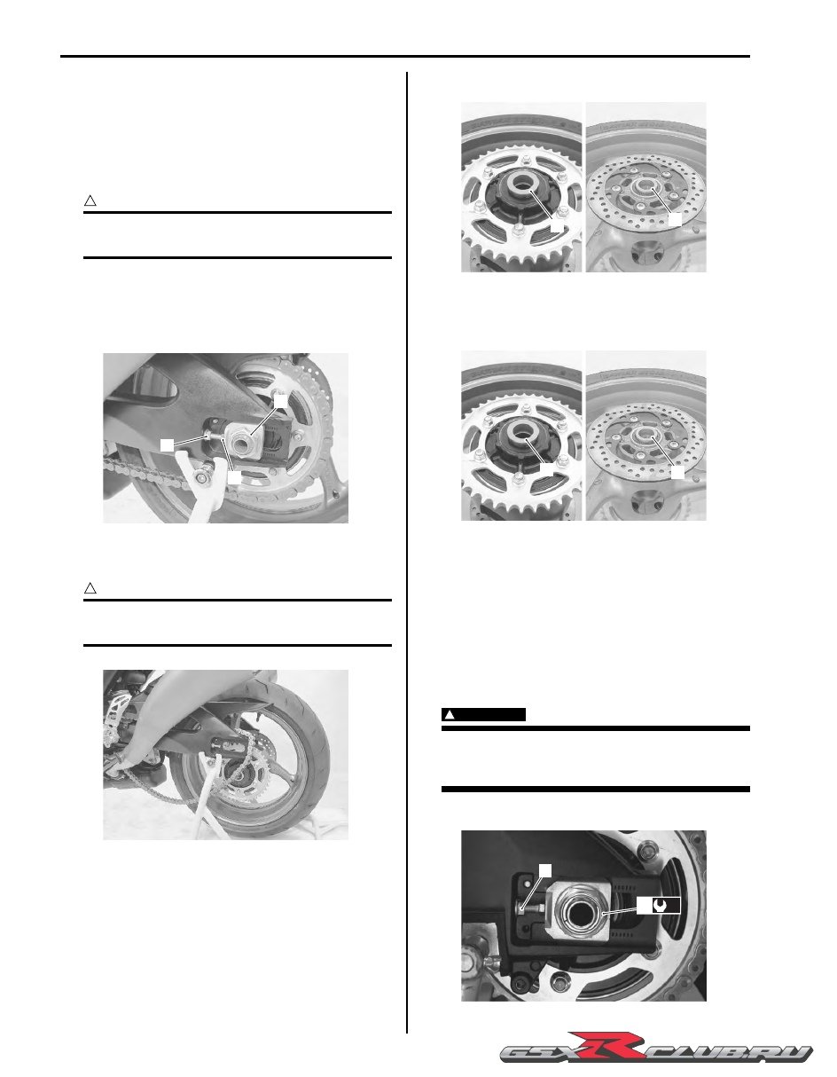
7) Remove the collars (5) and (6).

Installation

1) Install the collars (1) and (2).

2) Remount the rear wheel and rear axle, tighten the 

rear axle nut (3) temporarily.

3) Adjust the chain slack after installing the rear wheel. 

Refer to “Drive Chain Inspection and Adjustment” in 
Section 0B (Page 0B-14).

4) Tighten the rear axle nut (3) to the specified torque.

Tightening torque
Rear axle nut  (a):  100 N·m (10.0 kgf-m, 72.5 lbf-
ft)

WARNING

!


After remounting the rear wheel, pump the 
brake pedal several times to check for proper 
brake operation.


5) Tighten both chain adjuster lock-nut (4) securely.

1

2

3

I947H1240014-02

I947H1240015-01

6

5

I947H1240017-02

2

1

I947H1240026-02

4

(a)

3

I838H1240002-01

-------------------------------------------------------------------------------------------------------------------------------------------------------------

Wheels and Tires:  2D-12

Rear Wheel Related Parts Inspection

B947H12406009

Refer to “Rear Wheel Assembly Removal and 
Installation” (Page 2D-11).

Tire

Refer to “Tire Inspection” in Section 0B (Page 0B-18).

Rear Brake Disc

Refer to “Rear Brake Disc Inspection” in Section 4C 
(Page 4C-7)
.

Wheel Damper

Refer to “Drive Chain Related Parts Inspection” in 
Section 3A (Page 3A-5).

Sprocket

Refer to “Drive Chain Related Components” in Section 
3A (Page 3A-1).

Dust Seal

Inspect the dust seal lip for wear or damage. If any 
defects is found, replace the dust seal with a new one. 
Refer to “Rear Wheel Dust Seal / Bearing Removal and 
Installation” (Page 2D-13).

Wheel Axle

Using a dial gauge, check the wheel axle for runout, If 
the runout exceeds the limit, replace the axle shaft.

Wheel axle runout
Service limit: 0.25 mm (0.010 in)

Special tool

(A):  09900–20607 (Dial gauge)
(B):  09900–20701 (Dial gauge chuck)
(C):  09900–21304 (V blocks)

Wheel

1) Remove the rear brake pads. Refer to “Rear Brake 

Pad Replacement” in Section 4C (Page 4C-2).

2) Make sure that the wheel runout checked as shown 

in the figure does not exceed the service limit. An 
excessive runout is usually due to worn or loosened 
wheel bearings and can be reduced by replacing the 
bearings. If bearing replacement fails to reduce the 
runout, replace the wheel.

Wheel rim runout
Service limit (Axial and Radial): 2.0 mm (0.08 in)

3) Install the rear brake pads. Refer to “Rear Brake Pad 

Replacement” in Section 4C (Page 4C-2).

Bearing

Inspect the play of the wheel bearings by hand while 
they are in the wheel. Rotate the inner race by hand to 
inspect for abnormal noise and smooth rotation. Replace 
the bearing if there is anything unusual. Refer to “Rear 
Wheel Dust Seal / Bearing Removal and Installation” 
(Page 2D-13).

I947H1240018-02

(A)

(B)

(C)

I649G1230034-03

I649G1240014-02

I649G1240015-02

-------------------------------------------------------------------------------------------------------------------------------------------------------------

2D-13 Wheels and Tires: 

Rear Wheel Dust Seal / Bearing Removal and 
Installation

B947H12406010

Removal

1) Remove the rear wheel assembly. Refer to “Rear 

Wheel Assembly Removal and Installation” 
(Page 2D-11)
.

2) Remove the rear sprocket mounting drum assembly 

(1) from the rear wheel.

3) Remove the wheel dampers (2).

4) Remove the dust seal.

Special tool

(A):  09913–50121 (Oil seal remover)

5) Remove the bearings on both sides using the special 

tool.

Special tool

(B):  09921–20240 (Bearing remover set)

6) Remove the spacer (3).

Installation

CAUTION

!


The removed dust seal and bearings must be 
replaced with new ones.


1) Apply grease to the wheel bearings.

:  Grease 99000–25010 (SUZUKI SUPER 

GREASE “A” or equivalent)

1

I947H1240019-01

2

2

I947H1240020-02

(A)

I947H1240021-01

(B)

(B)

I947H1240022-01

3

I947H1240023-01

I649G1240019-02

-------------------------------------------------------------------------------------------------------------------------------------------------------------

Wheels and Tires:  2D-14

2) First install the right wheel bearing, then install the 

spacer (1) and left wheel bearing with the special 
tools.

Special tool

(A):  09941–34513 (Bearing installer)
(B):  09924–84510 (Bearing installer set)

CAUTION

!


The sealed cover of the bearing must face 
outside.


3) Install new dust seal with the special tool.

Special tool

(C):  09913–70210 (Bearing installing set (10 

– 75 

Φ

))

4) Install the rear sprocket mounting drum assembly 

(2).

5) Apply grease to the lip of dust seals.

:  Grease 99000–25010 (SUZUKI SUPER 

GREASE “A” or equivalent)

6) Install the rear wheel assembly. Refer to “Rear 

Wheel Assembly Removal and Installation” 
(Page 2D-11).

Tire Removal and Installation

B947H12406011

Removal

The most critical factor of a tubeless tire is the seal 
between the wheel rim and the tire bead. For this 
reason, it is recommended to use a tire changer that can 
satisfy this sealing requirement and can make the 
operation efficient as well as functional.

1) Removal the wheel assembly. Refer to “Front Wheel 

Assembly Removal and Installation” (Page 2D-4) 
and “Rear Wheel Assembly Removal and 
Installation” (Page 2D-11)
.

2) Remove the mounting drum from the rear wheel. 

(For rear wheel)
Refer to “Rear Wheel Assembly Removal and 
Installation” (Page 2D-11)
.

3) Remove the valve core.

1. Spacer

“a”: Clearance

(B)

(A)

I649G1240030-02

LH

RH

(A)

(B)

(A)

(B)

1

“ a ”

I947H1240032-01

(C)

I947H1240024-01

2

I947H1240025-03

-------------------------------------------------------------------------------------------------------------------------------------------------------------

2D-15 Wheels and Tires: 

4) Remove the tire using the tire changer.

CAUTION

!


For operating procedures, refer to the 
instructions supplied by the tire changer 
manufacturer.


NOTE

When removing the tire in case of repair or 
inspection, mark the tire with a chalk to 
indicate the tire position relative to the valve 
position. Even though the tire is refitted to 
the original position after repairing puncture, 
the tire may have to be balanced again since 
such a repair can cause imbalance.


Installation

CAUTION

!


Do not reuse the valve which has been once 
removed.


1) Apply tire lubricant to the tire bead.

CAUTION

!


Never use oil, grease or gasoline on the tire 
bead in place of tire lubricant.


2) Install the tire onto the wheel.

CAUTION

!


For installation procedure of tire onto the 
wheel, follow the instructions given by the 
tire changer manufacturer.


NOTE

• When installing the tire, the arrow “A” on 

the side wall should point to the direction 
of wheel rotation.

• Align the chalk mark put on the tire at the 

time of removal with the valve position.


3) Bounce the tire several times while rotating. This 

makes the tire bead expand outward to contact the 
wheel, thereby facilitating air inflation.

4) Install the valve core and inflate the tire.

WARNING

!


• Do not inflate the tire to more than 400 kPa 

(4.0 kgf/cm

2

, 57 psi). If inflated beyond this 

limit, the tire can burst and possibly cause 
injury. Do not stand directly over the tire 
while inflating.

• In the case of preset pressure air inflator, 

pay special care for the set pressure 
adjustment.


5) In this condition, check the “rim line” “B” cast on the 

tire side walls. The line must be equidistant from the 
wheel rim all around.

6) If the distance between the rim line and wheel rim 

varies, this indicates that the bead is not properly 
seated. If this is the case, deflate the tire completely 
and unseat the bead for both sides. Coat the bead 
with lubricant and fit the tire again.

I649G1240037-02

I649G1240038-02

“A”

I649G1240039-02

“B”

I649G1240040-02

-------------------------------------------------------------------------------------------------------------------------------------------------------------

Wheels and Tires:  2D-16

7) When the bead has been fitted properly, adjust the 

pressure to specification.

8) As necessary, adjust the tire balance. Refer to 

“Wheel Balance Check and Adjustment” (Page 2D-
17).

Cold inflation tire pressure

9) Install the mounting drum to the rear wheel.

(For rear wheel)
Refer to “Rear Wheel Assembly Removal and 
Installation” (Page 2D-11).

10) Install the wheel assembly. Refer to “Front Wheel 

Assembly Removal and Installation” (Page 2D-4) 
and “Rear Wheel Assembly Removal and 
Installation” (Page 2D-11).

Wheel / Tire / Air Valve Inspection and Cleaning

B947H12406012

Refer to “Tire Removal and Installation” (Page 2D-14).

Wheel

Wipe the wheel clean and check for the following points:

• Distortion and crack

• Any flaws and scratches at the bead seating area.

• Wheel rim runout. Refer to “Front Wheel Related 

Parts Inspection” (Page 2D-6) and “Rear Wheel 
Related Parts Inspection” (Page 2D-12).

Tire

Tire must be checked for the following points:

• Nick and rupture on side wall

• Tire tread depth (Refer to “Tire Inspection” in Section 

0B (Page 0B-18).)

• Tread separation

• Abnormal, uneven wear on tread

• Surface damage on bead

• Localized tread wear due to skidding (Flat spot)

• Abnormal condition of inner liner

Air Valve

Inspect the air valve for peeling and damage. If any 
defect is found, replace the air valve with a new one. 
Refer to “Air Valve Removal and Installation” (Page 2D-
16).

Inspect the valve core seal (1) for wear and damage. If 
any defect is found, replace the valve core with a new 
one. Refer to “Air Valve Removal and Installation” 
(Page 2D-16).

Air Valve Removal and Installation

B947H12406013

Removal

1) Remove the wheel assembly. Refer to “Front Wheel 

Assembly Removal and Installation” (Page 2D-4) 
and “Rear Wheel Assembly Removal and 
Installation” (Page 2D-11)
.

2) Remove the tire. Refer to “Tire Removal and 

Installation” (Page 2D-14).

Front

Rear

Solo 

riding

250 kPa

(2.50 kgf/cm

2

, 36 psi)

290 kPa

(2.90 kgf/cm

2

, 42 psi)

Dual 

riding

250 kPa

(2.50 kgf/cm

2

, 36 psi)

290 kPa

(2.90 kgf/cm

2

, 42 psi)

I649G1240041-02

1. Seal

I649G1240042-02

I649G1240043-02

I649G1240044-02

1

I649G1240045-02

-------------------------------------------------------------------------------------------------------------------------------------------------------------

2D-17 Wheels and Tires: 

3) Remove the air valve (1) from the wheel.

Installation

Install the air valve in the reverse order of removal. Pay 
attention to the following points: 

• Any dust or rust around the valve hole (1) must be 

cleaned off.

• Install the air valve (2) in the wheel (3).

CAUTION

!


• Be careful not to damage the valve lip (4) 

of the valve.

• Replace the air valve with a new one.


NOTE

To properly install the valve into the valve 
hole, apply a special tire lubricant or neutral 
soapy liquid to the valve.


Wheel Balance Check and Adjustment

B947H12406014

Check and adjust the wheel balance in the following 
procedures:

1) Removal the wheel assembly. Refer to “Front Wheel 

Assembly Removal and Installation” (Page 2D-4) 
and “Rear Wheel Assembly Removal and 
Installation” (Page 2D-11).

2) Remove the mounting drum from the rear wheel. 

(For rear wheel)
Refer to “Rear Wheel Assembly Removal and 
Installation” (Page 2D-11).

3) Check the wheel balance using the balancer and 

adjust the wheel balance if necessary.

CAUTION

!


For operating procedures, refer to the 
instructions supplied by the wheel balancer 
manufacturer.


4) When installing the balancer weight to the wheel, set 

the balancer weight on center rib of the wheel.

5) Recheck the wheel balance.

6) Install the mounting drum to the rear wheel. (For rear 

wheel)
Refer to “Rear Wheel Assembly Removal and 
Installation” (Page 2D-11).

7) Install the wheel assembly. Refer to “Front Wheel 

Assembly Removal and Installation” (Page 2D-4) 
and “Rear Wheel Assembly Removal and 
Installation” (Page 2D-11).

2. Valve

3. Wheel

4. Valve lip

1

I837H1240031-01

1

I837H1240032-01

2

3

4

I837H1240033-01

I947H1240029-01

-------------------------------------------------------------------------------------------------------------------------------------------------------------

Wheels and Tires:  2D-18

Specifications

Service Data

B947H12407001

Wheel

Unit: mm (in)

Tire

Tightening Torque Specifications

B947H12407002

NOTE

The specified tightening torque is described in the following.
“Front Wheel Components” (Page 2D-2)
“Front Wheel Assembly Construction” (Page 2D-3)
“Rear Wheel Components” (Page 2D-9)
“Rear Wheel Assembly Construction” (Page 2D-10)


Reference:

For the tightening torque of fastener not specified in this section, refer to “Tightening Torque List” in Section 0C 
(Page 0C-9)
.

Item

Standard

Limit

Wheel rim runout

Axial

2.0 (0.08)

Radial

Wheel rim size

Front

17 M/C x MT 3.50

Rear

17 M/C x MT 6.00

Wheel axle runout

Front

 0.25 (0.010)

Rear

Item

Standard

Limit

Cold inflation tire pressure
(Solo riding)

Front

250 kPa (2.50 kgf/cm

2

, 36 psi)

Rear

290 kPa (2.90 kgf/cm

2

, 42 psi)

Cold inflation tire pressure
(Dual riding)

Front

250 kPa (2.50 kgf/cm

2

, 36 psi)

Rear

290 kPa (2.90 kgf/cm

2

, 42 psi)

Tire size

Front

120/70 ZR17M/C (58 W)

Rear

190/50 ZR17M/C (73 W)

Tire type

Front

BRIDGESTONE BT016F N

Rear

BRIDGESTONE BT016R N

Tire tread depth 
(Recommended depth)

Front

1.6 mm (0.06 in)

Rear

2.0 mm (0.08 in)

Fastening part

Tightening torque

Note

N

m

kgf-m

lbf-ft

Front brake caliper mounting bolt

39

3.9 

28.0 

)

(Page 2D-5)

Front axle bolt

100

10.0 

72.5 

)

(Page 2D-5)

Front axle pinch bolt

23

2.3 16.5 

)

(Page 2D-5) / 

)

(Page 2D-5)

Rear axle nut 

100

10.0 

72.5 

)

(Page 2D-11)

-------------------------------------------------------------------------------------------------------------------------------------------------------------

2D-19 Wheels and Tires: 

Special Tools and Equipment

Recommended Service Material

B947H12408001

NOTE

Required service material is also described in the following.
“Front Wheel Components” (Page 2D-2)
“Front Wheel Assembly Construction” (Page 2D-3)
“Rear Wheel Components” (Page 2D-9)
“Rear Wheel Assembly Construction” (Page 2D-10)


Special Tool

B947H12408002

Material

SUZUKI recommended product or Specification

Note

Grease

SUZUKI SUPER GREASE “A” or 
equivalent

P/No.: 99000–25010

)

(Page 2D-7) / 

)

(Page 2D-

8) / 

)

(Page 2D-13) / 

)

(Page 2D-14)

09900–18740

09900–20607

Hexagon socket (24 mm)

Dial gauge

)

(Page 2D-5)

)

(Page 2D-6) / 

)

(Page 2D-

12)

09900–20701

09900–21304

Dial gauge chuck

V blocks

)

(Page 2D-6) / 

)

(Page 2D-

12)

)

(Page 2D-6) / 

)

(Page 2D-

12)

09913–50121

09913–70210

Oil seal remover

Bearing installing set (10 – 
75 

Φ

)

)

(Page 2D-7) / 

)

(Page 2D-

13)

)

(Page 2D-8) / 

)

(Page 2D-

14)

09921–20240

09924–84510

Bearing remover set

Bearing installer set

)

(Page 2D-7) / 

)

(Page 2D-

13)

)

(Page 2D-8) / 

)

(Page 2D-

14)

09941–34513
Bearing installer

)

(Page 2D-8) / 

)

(Page 2D-

14)

-------------------------------------------------------------------------------------------------------------------------------------------------------------

-------------------------------------------------------------------------------------------------------------------------------------------------------------

3-1 Precautions: 

Driveline / Axle

Precautions

Precautions

Precautions for Driveline / Axle

B947H13000001

Refer to “General Precautions” in Section 00 (Page 00-1).

WARNING

!


Never inspect or adjust the drive chain while the engine is running.


CAUTION

!


• Do not use trichloroethylene, gasoline or such similar solvent. These fluids will damage the O-rings 

of the drive chain.

• Clean the drive chain with a spray-type chain cleaner and blow dry with compressed air. If the drive 

chain cannot be cleaned with a spray cleaner, it may be necessary to use a kerosine. Always follow 
the chemical manufacturer’s instructions on proper use, handling and storage.

• Lubricate the drive chain with a heavy weight motor oil. Wipe off any excess oil or chain lubricant. 

Do not use any oil sold commercially as “drive chain oil”. Such oil can damage the O-rings.

• The standard drive chain is DID 50VAZ. Suzuki recommends to use this standard drive chain as a 

replacement.


-------------------------------------------------------------------------------------------------------------------------------------------------------------

Drive Chain / Drive Train / Drive Shaft:  3A-1

Driveline / Axle

Drive Chain / Drive Train / Drive Shaft

Diagnostic Information and Procedures

Drive Chain and Sprocket Symptom Diagnosis

B947H13104001

Repair Instructions

Drive Chain Related Components

B947H13106001

Condition

Possible cause

Correction / Reference Item

Noisy Drive Chain

Worn sprocket.

Replace.

Worn drive chain.

Replace.

Stretched drive chain.

Replace.

Too large drive chain slack.

Adjust.

Drive chain out of adjustment.

Adjust.

1

2

3

5

6

7

8

4

FWD

FWD

(a)

(b)

I947H1310028-01

1. Drive chain

6. Retainer

: Apply grease.

2. Engine sprocket

7. Sprocket mounting drum

: Apply thread lock to thread part.

3. Rear sprocket

8. Wheel damper

: Do not reuse.

4. Dust seal

: 145 N

m (14.5 kgf-m, 105.0 lbf-ft)

5. Bearing

: 60 N

m (6.0 kgf-m, 43.0 lbf-ft)

-------------------------------------------------------------------------------------------------------------------------------------------------------------

3A-2 Drive Chain / Drive Train / Drive Shaft: 

Engine Sprocket Removal and Installation

B947H13106002

Removal

1) Remove the gearshift link arm (1) from the gearshift 

shaft.

NOTE

Mark the gearshift shaft head at which the 
gearshift link arm slit set for correct 
reinstallation.


2) Remove the speed sensor (2).

3) Remove the engine sprocket cover (3).

4) Support the motorcycle with a jack or wooden block.

5) Loosen the rear axle nut (4) and left and right chain 

adjuster lock-nuts (5).

6) Loosen the chain adjusters (6) to provide additional 

chain slack.

7) Remove the speed sensor rotor (7) by removing its 

bolt while depressing the rear brake pedal.

8) Remove the engine sprocket nut (8) while 

depressing the rear brake pedal.

9) Remove the washer (9).

10) Remove the engine sprocket (10).

Installation

Install the engine sprocket in the reverse order of 
removal. Pay attention to the following points:

• Apply thread lock to the driveshaft.

:  Thread lock cement 99000–32110 

(THREAD LOCK CEMENT SUPER “1322” or 
equivalent)

1

I947H1310018-01

2

3

I947H1310019-01

4

5

6

I947H1310020-01

7

I947H1310021-01

8

I947H1310022-01

9

10

I947H1310023-01

-------------------------------------------------------------------------------------------------------------------------------------------------------------

Drive Chain / Drive Train / Drive Shaft:  3A-3

• Tighten the engine sprocket nut (1) to the specified 

torque.

Tightening torque
Engine sprocket nut (a):  145 N·m (14.5 kgf-m, 
105.0 lbf-ft)

• Tighten the speed sensor rotor bolt (2) to the specified 

torque.

Tightening torque
Speed sensor rotor bolt (b):  28 N·m (2.8 kgf-m, 
20.0 lbf-ft)

• Before installing the engine sprocket cover, apply a 

small quantity of grease to the clutch push rod.

:  Grease 99000–25010 (SUZUKI SUPER 

GREASE “A” or equivalent)

• Install the engine sprocket cover (3).

• Tighten the speed sensor mounting bolt (4) to the 

specified torque.

Tightening torque
Speed sensor mounting bolt (c):  6.5 N·m (0.65 
kgf-m, 4.5 lbf-ft)

• Fit the gearshift link arm to the gearshift shaft so that 

the gearshift lever is located at height “a” below the 
footrest.

Gearshift lever height “a”
Standard: 65 – 75 mm (2.6 – 3.0 in)

• Adjust the drive chain slack. Refer to “Drive Chain 

Inspection and Adjustment” in Section 0B (Page 0B-
14).

Rear Sprocket / Rear Sprocket Mounting Drum 
Removal and Installation

B947H13106003

Removal

1) Remove the rear wheel assembly. Refer to “Rear 

Wheel Assembly Removal and Installation” in 
Section 2D (Page 2D-11).

2) Loosen the rear sprocket nuts.

3) Draw out the rear sprocket mounting drum (1) along 

with the rear sprocket (2) from the wheel hub.

4) Remove the rear sprocket nuts and separate the 

rear sprocket (2) from its mounting drum (1).

(a)

1

I947H1310024-01

(b)

2

I947H1310025-01

(c)

4

3

I947H1310026-01

“ a ”

I947H1310001-01

1

2

I947H1310002-01

-------------------------------------------------------------------------------------------------------------------------------------------------------------

3A-4 Drive Chain / Drive Train / Drive Shaft: 

5) Remove the retainer (3).

6) Remove the wheel dampers (4).

Installation

Install the rear sprocket and rear sprocket mounting 
drum in the reverse order of removal. Pay attention to 
the following points:

• Apply grease to the contacting surface between the 

rear wheel hub and rear sprocket mounting drum.

:  Grease 99000–25010 (SUZUKI SUPER 

GREASE “A” or equivalent)

• Apply special tire lubricant or neutral soapy liquid to 

the wheel damper surfaces “A”.

CAUTION

!


Never use oil, grease or gasoline on the 
wheel damper in place of the tire lubricant or 
neutral soapy liquid.


• Apply grease to the retainer.

:  Grease 99000–25010 (SUZUKI SUPER 

GREASE “A” or equivalent)

• Install the rear sprocket so that the letters “B” face 

outside.

• Tighten the rear sprocket nuts to the specified torque.

Tightening torque
Rear sprocket nut (a):  60 N·m (6.0 kgf-m, 43.0 lbf-
ft)

• Install the rear wheel assembly. Refer to “Rear Wheel 

Assembly Removal and Installation” in Section 2D 
(Page 2D-11).

3

I947H1310003-01

4

4

I947H1310004-01

“A”

I947H1310005-01

I947H1310006-01

“B”

I947H1310007-01

(a)

I947H1310008-01

-------------------------------------------------------------------------------------------------------------------------------------------------------------

Drive Chain / Drive Train / Drive Shaft:  3A-5

Drive Chain Related Parts Inspection

B947H13106004

Refer to “Rear Sprocket / Rear Sprocket Mounting Drum 
Removal and Installation” (Page 3A-3).

Dust Seal

Inspect the dust seal for wear or damage. If any damage 
is found, replace the dust seal with a new one.

Bearing

Inspect the play of the sprocket mounting drum bearing 
by hand while it is in the drum. Rotate the inner race by 
hand to inspect for abnormal noise and smooth rotation. 
Replace the bearing if there is anything unusual.

Engine Sprocket and Rear Sprocket

Inspect the sprocket teeth for wear. If they are worn as 
shown, replace the engine sprocket, rear sprocket and 
drive chain as a set.

Wheel Damper

Inspect the dampers for wear and damage. Replace the 
dampers if there is anything unusual.

Drive Chain

Refer to “Drive Chain Inspection and Adjustment” in 
Section 0B (Page 0B-14)
.

Sprocket Mounting Drum Dust Seal / Bearing 
Removal and Installation

B947H13106005

Removal

1) Remove the rear wheel assembly. Refer to “Rear 

Wheel Assembly Removal and Installation” in 
Section 2D (Page 2D-11).

2) Remove the rear sprocket mounting drum assembly 

(1). Refer to “Rear Sprocket / Rear Sprocket 
Mounting Drum Removal and Installation” (Page 3A-
3)
.

3) Remove the retainer (2).

“A”: Normal wear

“B”: Excessive wear

I947H1310009-01

I649G1310015-02

“A”

“B”

I947H1310010-01

I947H1310011-01

1

I947H1310012-01

2

I947H1310013-01

-------------------------------------------------------------------------------------------------------------------------------------------------------------


Content      ..     28      29      30      31     ..