Suzuki GSX-R1000. Service Manual - part 21
1E-2 Engine Lubrication System:
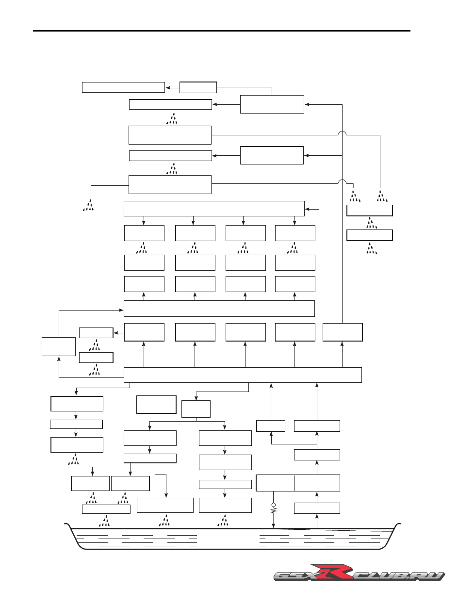
Schematic and Routing Diagram
Engine Lubrication System Chart Diagram
B947H11502001
INTAKE CAMSHAFT
INTAKE CAMSHAFT
JOURNAL HOLDER
CAM CHAIN
STARTER CLUTCH
OIL JET (#16)
CAM CHAIN TENSION ADJUSTER
#1 PISTON COOLING
OIL JET
#1 PISTON AND
CYLINDER WALL
#1 CRANK PIN
BEARING
#1 CRANKSHAFT
JOURNAL BEARING
ORIFICE
GENERATOR
GENERATOR
COVER
#2 CRANKSHAFT
JOURNAL BEARING
#3 CRANKSHAFT
JOURNAL BEARING
#4 CRANKSHAFT
JOURNAL BEARING
#5 CRANKSHAFT
JOURNAL BEARING
OIL PRESSURE
SWITCH
#2 CRANK PIN
BEARING
OIL JET
(#14)
OIL FILTER
OIL COOLER
OIL PUMP
ORIFICE
OIL STRAINER
OIL PRESSUER
REGULATOR
COUNTERSHAFT
LEFT BEARING
BALANCERSHAFT
RIGHT BEARING
COUNTERSHAFT
CLUTCH PUSH
PIECE
CLUTCH PLATES
PRIMARY DRIVEN
GEAR BEARING
COUNTERSHAFT
RIGHT BEARING
DRIVESHAFT
RIGHT BEARING
#3 CRANK PIN
BEARING
#4 CRANK PIN
BEARING
#2 PISTON AND
CYLINDER WALL
#3 PISTON AND
CYLINDER WALL
#4 PISTON AND
CYLINDER WALL
#2 PISTON COOLING
OIL JET
#3 PISTON COOLING
OIL JET
#4 PISTON COOLING
OIL JET
EXHAUST CAMSHAFT
INTAKE CAMSHAFT JOURNALS,
CAMFACES AND TAPPETS
EXHAUST CAMSHAFT JOURNALS,
CAMFACES AND TAPPETS
SUB GALLERY
MAIN GALLERY
CRANKSHAFT
OIL PAN
EXHAUST CAMSHAFT
JOURNAL HOLDER #1
BALANCERSHAFT
BALANCERSHAFT
LEFT BEARING
DRIVESHAFT
DRIVESHAFT GEARS
AND BUSHINGS
COUNTERSHAFT GEARS
AND BUSHINGS
I947H1150001-03