Suzuki GSX-R1000. Service Manual - part 19


  Index      Manuals     Suzuki GSX-R1000. Service Manual


Search            copyright infringement  


Content      ..     17      18      19      20     ..


Suzuki GSX-R1000. Service Manual - part 19


1D-60 Engine Mechanical: 

2) Position the No. 2 and No. 3 conrod big ends on the 

same side, and the No. 1 and No. 4 conrod big ends 
on the opposite side of No. 2 and No. 3.

3) Set the crankshaft onto the conrods and upper 

crankcase.

4) Apply molybdenum oil to each crank pin and bearing 

surface.

CAUTION

!


Be sure to clean the conrod big end.


M/O:  Molybdenum oil  (MOLYBDENUM OIL 
SOLUTION) 

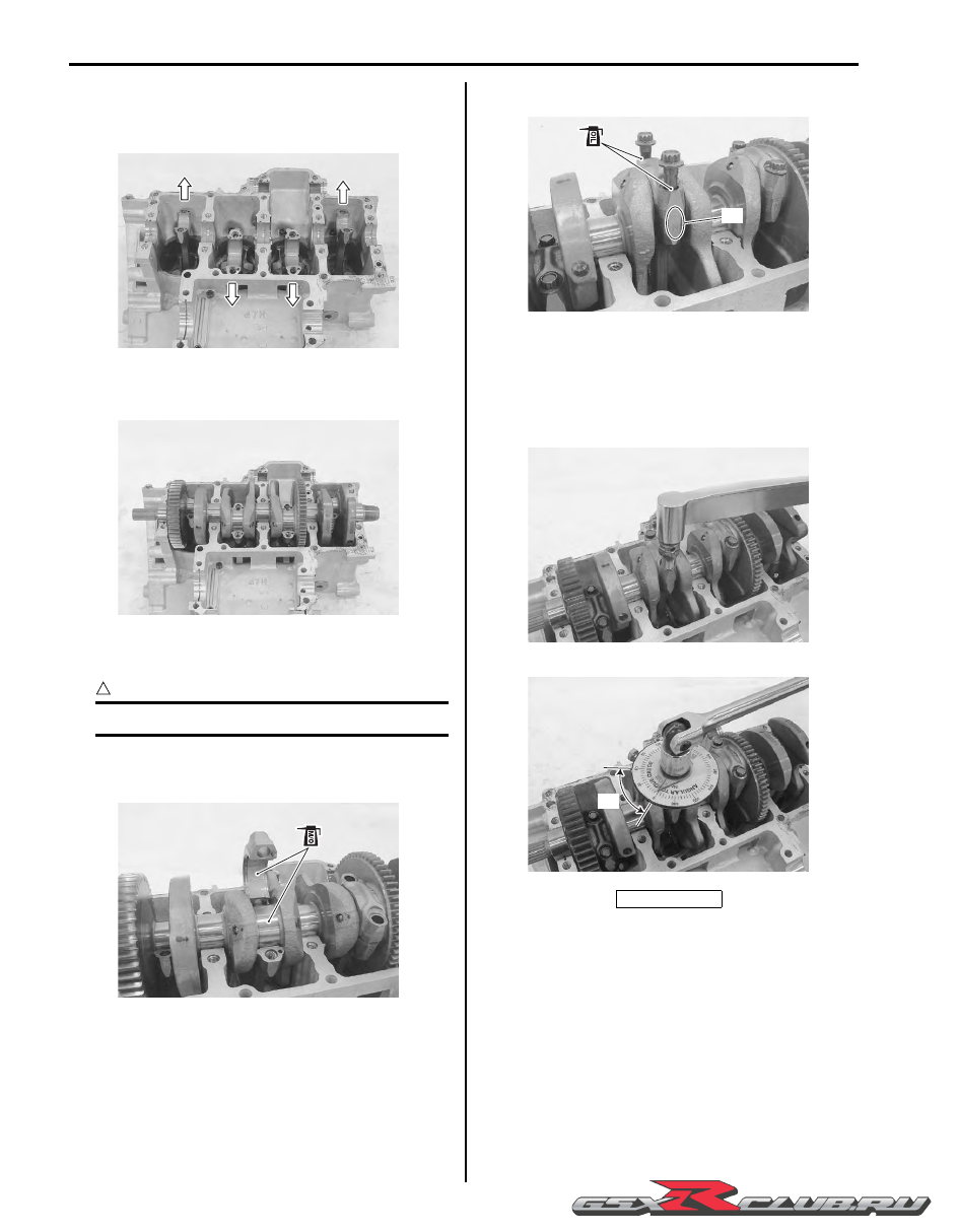
5) When fitting the conrod cap, make sure that I.D. 

code “A” on each conrod faces intake side.

6) Apply engine oil to the conrod cap bolts.

7) Tighten the conrod cap bolt by using a 10 mm, 12 

point socket wrench in the following two steps.

Tightening torque
Conrod cap bolt:  37 N

m (3.7 kgf-m, 26.5 lbf-ft) 

then turn in 1/6 (60

°

) turn

8) Apply engine oil to the conrod big end side surfaces.

9) Apply molybdenum oil to each crankshaft journal and 

bearing lightly.

M/O:  Molybdenum oil  (MOLYBDENUM OIL 
SOLUTION) 

I947H1140170-01

I947H1140171-01

I947H1140172-01

“a”: 60

°

“A”

I947H1140173-01

I947H1140174-01

“ a ”

I947H1140175-01

-------------------------------------------------------------------------------------------------------------------------------------------------------------

Engine Mechanical:  1D-61

10) Check the conrod movement for smooth turning.

11) Insert the right and left thrust bearings with the oil 

grooves “B” facing towards the crankshaft web.

NOTE

• Right-thrust bearing has green painting.

• Inspect and select the crankshaft thrust 

clearance if necessary. Refer to 
“Crankshaft Thrust Clearance Inspection 
and Selection” (Page 1D-82).


Transmission

Install the transmission. Refer to “Transmission 
Installation” in Section 5B (Page 5B-5)
.

Balancer Shaft

• Apply a molybdenum oil solution to each balancer 

shaft journal and bearing lightly.

M/O:  Molybdenum oil  (MOLYBDENUM OIL 
SOLUTION)

• Set the balancer shaft so that its punch mark “A” is 

aligned with the index “B” on the crankshaft.

• Install the plug (1).

I947H1140176-01

“B”

“B”

I947H1140177-02

I947H1140178-01

I947H1140179-01

“A”

“B”

I947H1140180-01

1

I947H1140181-01

-------------------------------------------------------------------------------------------------------------------------------------------------------------

1D-62 Engine Mechanical: 

Crankcase

• Install the dowel pins and O-rings (1).

CAUTION

!


Replace the O-rings with new ones.


• Apply bond to the mating surface of the lower 

crankcase as follows.

NOTE

• Make mating surfaces free from moisture, 

oil, dust and other foreign materials.

• Spread the sealant on surfaces thinly to 

form an even layer, and assemble the 
crankcases within a few minutes.

• Take extreme care not to apply sealant to 

any oil hole, oil groove and bearing.

• Apply sealant to distorted surfaces as it 

forms a comparatively thick film.


:  Sealant 99000–31140 (SUZUKI BOND 

No.1207B or equivalent)

1

I947H1140182-02

I947H1140183-02

: Apply bond.

-------------------------------------------------------------------------------------------------------------------------------------------------------------

Engine Mechanical:  1D-63

• Tighten the crankshaft journal bolts (M9). Tighten 

each bolt a little at a time to equalize the pressure in 
the following two steps.

CAUTION

!


Fit new gasket washers to the bolts “A” to 
prevent oil leakage.


Tightening torque
Crankshaft journal bolt (M9):  18 N

m (1.8 kgf-m, 

13.0 lbf-ft) then turn in 50

°

• Tighten the crankcase bolts a little at a time to 

equalize the pressure.

• Install the cap (2).

CAUTION

!


• Fit new gasket washers to the bolts “B” to 

prevent oil leakage.

• Fit new O-ring to the cap (2) and apply 

grease to it.


Tightening torque
Crankcase bolt (M8) (Initial):  15 N·m (1.5 kgf-m, 
11.0 lbf-ft)
Crankcase bolt (M8) (Final):  26 N·m (2.6 kgf-m, 
19.0 lbf-ft)
Crankcase bolt (M6):  12 N·m (1.2 kgf-m, 8.5 lbf-ft)

• After the crankshaft journal bolts and crankcase bolts 

have been tightened, check that the crankshaft 
rotates smoothly.

• Also check that the driveshaft and countershaft rotate 

smoothly.

• Install the clutch push rod oil seal retainer (3).

“A”

“A”

I947H1140184-01

I947H1140185-01

I947H1140186-02

“B”

“B”

“B”

2

I947H1140187-03

I947H1140188-01

I947H1140189-01

-------------------------------------------------------------------------------------------------------------------------------------------------------------

1D-64 Engine Mechanical: 

• Apply thread lock to the bolts.

:  Thread lock cement 99000–32110 

(THREAD LOCK CEMENT SUPER “1322” or 
equivalent)

Oil Pump

• Install the breather oil return pipe (1).

• Apply grease to new O-ring (2).

:  Grease 99000–25010 (SUZUKI SUPER 

GREASE “A” or equivalent)

CAUTION

!


Use a new O-ring to prevent oil leakage.


• Install the O-ring and dowel pins.

• Install the oil pump (3) and tighten the oil pump bolts 

to the specified torque.

Tightening torque
Oil pump mounting bolt:  10 N·m (1.0 kgf-m, 7.0 
lbf-ft)

• Install the thrust washer (4) to the countershaft.

NOTE

The chamfer side “A” of thrust washer 
should face the crankcase side.


• Install the oil pump drive sprocket (5) to the 

countershaft.

NOTE

Teeth “B” on the sprocket must face the 
clutch side.


• Pass the chain (6) between the oil pump drive and 

driven sprockets.

• Apply engine oil to the countershaft.

3

I947H1140190-02

1

I947H1140191-01

2

I947H1140192-01

3

I947H1140193-01

4

“A”

I947H1140194-01

6

“B”

5

I947H1140195-02

-------------------------------------------------------------------------------------------------------------------------------------------------------------

Engine Mechanical:  1D-65

• Apply engine oil to the bearing (7) and spacer (8) and 

install them into the sprocket.

Oil Strainer / Oil Pressure Regulator

• Apply grease to new O-ring (1).

CAUTION

!


Use a new O-ring to prevent oil leakage.


:  Grease 99000–25010 (SUZUKI SUPER 

GREASE “A” or equivalent)

• Install the oil strainer (2).

• Apply grease to new O-ring (3).

CAUTION

!


Use a new O-ring to prevent oil leakage.


:  Grease 99000–25010 (SUZUKI SUPER 

GREASE “A” or equivalent)

• Push in the oil pressure regulator (4) to the oil pump 

as shown.

Oil Pan

• Install new gasket.

CAUTION

!


Use new gasket to prevent oil leakage.


• Install the oil pan (1) and plate (2).

• Apply thread lock to the plate bolts “A”.

:  Thread lock cement 99000–32110 

(THREAD LOCK CEMENT SUPER “1322” or 
equivalent)

• Tighten the oil pan bolts and plate bolts diagonally to 

the specified torque.

Tightening torque
Oil pan bolt:  10 N·m (1.0 kgf-m, 7.0 lbf-ft)

Oil Filter

Install the oil filter with the special tool. Refer to “Engine 
Oil and Filter Replacement” in Section 0B (Page 0B-10).

Special tool

(A):  09915–40610 (Oil filter wrench)

7

8

I947H1140196-01

1

2

I947H1140197-01

3

4

I947H1140198-02

2

1

“A”

I947H1140298-01

(A)

I947H1140201-01

-------------------------------------------------------------------------------------------------------------------------------------------------------------

1D-66 Engine Mechanical: 

Oil Pressure Switch

• Apply bond to the thread part of oil pressure switch 

and tighten oil pressure switch to the specified torque.

NOTE

Be careful not to apply bond to the hole of 
thread end.


:  Sealant 99000–31140 (SUZUKI BOND 

No.1207B or equivalent)

Tightening torque
Oil pressure switch:  14 N·m (1.4 kgf-m, 10.0 lbf-ft)

• Route the oil pressure switch lead wire properly and 

tighten the screw to the specified torque. Refer to 
“Wiring Harness Routing Diagram” in Section 9A 
(Page 9A-7).

Gear Position Switch

• Apply grease to the O-ring.

CAUTION

!


Replace the O-ring with a new one.


NOTE

Insert the gear position switch pin “A” into 
the gearshift cam hole “B”.


:  Grease 99000–25010 (SUZUKI SUPER 

GREASE “A” or equivalent)

• Tighten the gear position switch mounting bolts to the 

specified torque.

Tightening torque
Gear position switch mounting bolt (a):  6.5 N·m (
0.65 kgf-m, 4.7 lbf-ft)

Water Pump

• Apply grease to new O-ring (1).

CAUTION

!


Use the new O-ring to prevent oil leakage.


:  Grease 99000–25010 (SUZUKI SUPER 

GREASE “A” or equivalent)

• Install the water pump assembly with the slot of the 

pump shaft end “A” securely engaged with the flat “B” 
of the oil pump shaft.

I718H1140233-01

“A”

“B”

I947H1140202-01

(a)

I947H1140203-01

1

“A”

“B”

I947H1140204-02

-------------------------------------------------------------------------------------------------------------------------------------------------------------

Engine Mechanical:  1D-67

• Tighten the water pump mounting bolts (2) to the 

specified torque.

Tightening torque
Water pump mounting bolt (a):  10 N·m (1.0 kgf-
m, 7.0 lbf-ft)

• Apply engine coolant to the O-ring.

CAUTION

!


Replace the O-ring with a new one.


• Tighten the water inlet connector mounting bolts.

Generator

Install the generator rotor and cover (1). Refer to 
“Generator Removal and Installation” in Section 1J 
(Page 1J-4).

Cam Chain / Cam Chain Tensioner / Cam Chain 
Guide No. 1

• Install the cam chain drive sprocket (1) to the 

crankshaft.

NOTE

When installing the cam chain drive sprocket, 
align the wide spline teeth of the sprocket 
and crankshaft.


• Install the cam chain (2).

• Insert the cam chain tensioner and tighten the cam 

chain tensioner bolt (3) to the specified torque.

Tightening torque
Cam chain tensioner bolt (a):  23 N·m (2.3 kgf-m, 
16.5 lbf-ft)

• Insert the cam chain guide No. 1 while pulling the 

chain upward.

• Tighten the cam chain guide No. 1 bolt (4) to the 

specified torque.

Tightening torque
Cam chain guide No. 1 bolt (b):  23 N·m (2.3 kgf-
m, 16.5 lbf-ft)

(a)

2

I947H1140205-02

I947H1140206-01

1

I947H1140207-01

1

2

I947H1140208-01

(a)

3

(b)

4

I947H1140209-01

-------------------------------------------------------------------------------------------------------------------------------------------------------------

1D-68 Engine Mechanical: 

• Install the washer (5).

Starter Clutch / Starter Torque Limiter

Install the starter clutch (1) and starter torque limiter (2) 
component parts. Refer to “Starter Clutch Removal and 
Installation” in Section 1I (Page 1I-10) and
 “Starter 
Torque Limiter Removal and Installation” in Section 1I 
(Page 1I-9)
.

Gearshift System

Install the gearshift cam plate (1) and gearshift shaft (2). 
Refer to “Gearshift Shaft / Gearshift Cam Plate Removal 
and Installation” in Section 5B (Page 5B-17).

Clutch

Install the clutch component parts (1). Refer to “Clutch 
Installation” in Section 5C (Page 5C-7).

Starter Motor

Install the starter motor (1). Refer to “Starter Motor 
Removal and Installation” in Section 1I (Page 1I-4).

Crankcase Breather (PCV) Cover

• Apply bond to the hatching part of crankcase breather 

(PCV) cover.

:  Sealant 99000–31140 (SUZUKI BOND 

No.1207B or equivalent)

• Fit the clamp to the bolt “A”. Refer to “Wiring Harness 

Routing Diagram” in Section 9A (Page 9A-7).

5

I947H1140210-01

1

2

I947H1140211-02

1

2

I947H1140212-01

1

I947H1140213-01

1

I947H1140214-02

I947H1140293-01

-------------------------------------------------------------------------------------------------------------------------------------------------------------

Engine Mechanical:  1D-69

• Tighten the crankcase breather (PCV) cover bolts.

Engine Top Side

Assemble the engine top side. Refer to “Engine Top Side 
Disassembly” (Page 1D-26).

Cylinder Inspection

B947H11406033

Refer to “Engine Top Side Disassembly” (Page 1D-26).
Refer to “Engine Top Side Assembly” (Page 1D-28).

Cylinder Distortion

Check the gasket surface of the cylinder for distortion. 
Use a straightedge and thickness gauge. Take clearance 
readings at several places. If any reading exceeds the 
service limit, replace the crankcase set.

Special tool

:  09900–20803 (Thickness gauge)

Cylinder distortion
Service limit: 0.02 mm (0.0008 in)

Cylinder Bore

Measure the cylinder bore diameter at six places. If any 
one of the measurements exceed the limit, overhaul the 
cylinder and replace the piston with an oversize piston. 
The remaining cylinders must also be rebored 
accordingly; otherwise, the imbalance might cause 
excessive vibration.

Special tool

(A):  09900–20530 (Cylinder gauge set)

Cylinder bore
Standard: 74.500 – 74.515 mm (2.9331 – 2.9337 in)

Piston-to-cylinder Clearance

Refer to “Piston and Piston Ring Inspection” (Page 1D-
71).

Piston Ring Removal and Installation

B947H11406034

Removal

1) Remove the piston. Refer to “Engine Bottom Side 

Disassembly” (Page 1D-49).

2) Carefully spread the ring opening with your thumbs 

and then push up the opposite side of the 1st ring to 
remove it.

NOTE

Do not expand the piston ring excessively 
since it is apt to be broken down.


3) Remove the 2nd ring and oil ring in the same 

manner.

“A”

I947H1140215-03

I947H1140216-01

(A)

I947H1140217-02

I837H1140180-01

I837H1140181-01

-------------------------------------------------------------------------------------------------------------------------------------------------------------

1D-70 Engine Mechanical: 

Installation

NOTE

• When installing the piston ring, be careful 

not to damage the piston.

• Do not expand the piston ring excessively 

since it is apt to be broken down.


1) Install the piston rings in the order of the oil ring, 

second ring and top ring.

a) The first member to go into the oil ring groove is 

the spacer (1).
After placing the spacer, fit the two side rails (2).

CAUTION

!


When installing the spacer, be careful not to 
allow its two ends to overlap in the groove.


b) Install the 2nd ring (3) and 1st ring (4) to piston.

NOTE

1st ring (4) and 2nd ring (3) differ in shape.


NOTE

Face the side with the stamped mark upward 
when assembling.


2) Position the gaps of the three rings and side rails as 

shown. Before inserting piston into the cylinder, 
check that the gaps are so located.

3) Install each piston and piston pin. Refer to “Engine 

Bottom Side Assembly” (Page 1D-56).

“A”: INCORRECT

“B”: CORRECT

1

2

2

I718H1140143-02

A

B

“A”

“B”

I705H1140170-02

“C”: 1st ring and upper side rail

“D”: Spacer

“E”: 2nd ring and lower side rail

[A]: IN

[B]: EX

3

4

I947H1140218-01

I947H1140219-01

“C”

“D”

“E”

[A]

[B]

I837H1140282-02

-------------------------------------------------------------------------------------------------------------------------------------------------------------

Engine Mechanical:  1D-71

Piston and Piston Ring Inspection

B947H11406035

Refer to “Piston Ring Removal and Installation” 
(Page 1D-69)
.

Piston Diameter

Measure the piston diameter using the micrometer at 15 
mm (0.6 in) “a” from the skirt end. If the piston diameter 
is less than the service limit, replace the piston.

Special tool

(A):  09900–20203 (Micrometer (50 – 75 mm))

Piston diameter
Service limit: 74.380 mm (2.9283 in)

Piston-to-cylinder Clearance

Subtract the piston diameter from the cylinder bore 
diameter. If the piston-to-cylinder clearance exceeds the 
service limit, replace both the cylinder and the piston.

Piston-to-cylinder clearance
Service limit: 0.120 mm (0.0047 in)

Piston Ring-to-groove Clearance

Measure the side clearances of the 1st and 2nd piston 
rings using the thickness gauge. If any of the clearances 
exceed the limit, replace both the piston and piston 
rings.

Special tool

(A):  09900–20803 (Thickness gauge)
(B):  09900–20205 (Micrometer (0 – 25 mm))

Piston ring-to-groove clearance
Service limit (1st): 0.180 mm (0.0071 in)
Service limit (2nd): 0.150 mm (0.0059 in)

Piston ring groove width
Standard (1st): 0.83 – 0.85 mm (0.0327 – 0.0335 in)
Standard (1st): 1.30 – 1.32 mm (0.0512 – 0.0520 in)
Standard (2nd): 0.81 – 0.83 mm (0.0319 – 0.0327 in)
Standard (Oil): 1.51 – 1.53 mm (0.0594 – 0.0602 in)

Piston ring thickness
Standard (1st): 0.76 – 0.81 mm (0.0299 – 0.0319 in)
Standard (1st): 1.08 – 1.10 mm (0.0425 – 0.0433 in)
Standard (2nd): 0.77 – 0.79 mm (0.0303 – 0.0311 in)

“a”: 10 mm (0.4 in)

“ a ”

I837H1140184-01

(A)

I649G1140262-03

(A)

I649G1140263-03

(B)

I649G1140264-03

-------------------------------------------------------------------------------------------------------------------------------------------------------------

1D-72 Engine Mechanical: 

Piston Ring Free End Gap and Piston Ring End Gap

Measure the piston ring free end gap using vernier 
calipers. Next, fit the piston ring squarely into the 
cylinder and measure the piston ring end gap using the 
thickness gauge. If any of the measurements exceed the 
service limit, replace the piston ring with a new one.

Special tool

(A):  09900–20102 (Vernier calipers (200 mm))

Piston ring free end gap
Service limit (1st): 5.6 mm (0.22 in)
Service limit (2nd): 6.4 mm (0.25 in)

Special tool

(B):  09900–20803 (Thickness gauge)

Piston ring end gap
Service limit (1st): 0.50 mm (0.020 in)
Service limit (2nd): 0.50 mm (0.020 in)

Piston Pin and Pin Bore

Measure the piston pin bore inside diameter using the 
small bore gauge. If either is out of specification or the 
difference between these measurements surpass limits, 
replace the piston.

Special tool

(A):  09900–20602 (Dial gauge)
(B):  09900–22401 (Small bore gauge (10 – 18 

mm))

Piston pin bore
Service limit: 15.030 mm (0.5917 in)

Measure the piston pin outside diameter at three 
positions using the micrometer. If any of the 
measurements are out of specification, replace the 
piston pin.

Special tool

(C):  09900–20205 (Micrometer (0 – 25 mm))

Piston pin O.D.
Service limit: 14.980 mm (0.5898 in)

(A)

I649G1140265-03

I947H1140307-01

(A)

(B)

I649G1140267-03

(C)

I649G1140268-03

-------------------------------------------------------------------------------------------------------------------------------------------------------------

Engine Mechanical:  1D-73

Balancer Shaft Disassembly and Assembly

B947H11406036

Refer to “Engine Bottom Side Disassembly” (Page 1D-
49)
.
Refer to “Engine Bottom Side Assembly” (Page 1D-56).

Disassembly

1) Remove the balancer shaft. Refer to “Engine Bottom 

Side Disassembly” (Page 1D-49).

2) Remove the washers, balancer gear and dampers 

from the shaft.

Assembly

Assembly is in the reverse order of disassembly. Pay 
attention to the following points:

• Apply molybdenum oil solution to each part.

M/O:  Molybdenum oil  (MOLYBDENUM OIL 
SOLUTION)

• Set the dampers and install the balancer shaft to 

balancer gear.

NOTE

• Fit the stopper of the balancer shaft 

between the dampers.

• Align the line “A” on the balancer shaft 

with the punch “B” on the balancer gear.


Balancer Shaft Inspection

B947H11406037

Refer to “Balancer Shaft Disassembly and Assembly” 
(Page 1D-73).

Balancer Shaft

Inspect the balancer shaft for wear or damage. Replace 
the balancer shaft if there is anything unusual.

Damper

Inspect the dampers for wear and damage, replace them 
if any defects are found.

I947H1140221-01

I947H1140222-01

“B”

“A”

I838H1140055-01

I947H1140223-01

-------------------------------------------------------------------------------------------------------------------------------------------------------------

1D-74 Engine Mechanical: 

Balancer Shaft Journal Bearing Removal and 
Installation

B947H11406038

Refer to “Engine Bottom Side Disassembly” (Page 1D-
49).
Refer to “Engine Bottom Side Assembly” (Page 1D-56).

Removal

Remove the balancer shaft journal bearings (1).

NOTE

• Do not remove the bearings (1) unless 

absolutely necessary.

• Make a note of where the bearings are 

removed from so that they can be 
reinstalled in their original positions.


CAUTION

!


When removing the bearings, be careful not 
to scratch the bearings.


Installation

When installing the bearings to the crankcases, be sure 
to install the tab “A” first, and then press in the other 
opposite side of the bearing.

NOTE

Inspect and select the balancer shaft journal 
bearing if necessary. Refer to “Balancer Shaft 
Journal Bearing Inspection and Selection” 
(Page 1D-75)
.


1

I947H1140224-02

1

I947H1140225-01

“A”

I947H1140226-01

“A”

I947H1140227-02

-------------------------------------------------------------------------------------------------------------------------------------------------------------

Engine Mechanical:  1D-75

Balancer Shaft Journal Bearing Inspection and 
Selection

B947H11406039

Refer to “Engine Bottom Side Disassembly” (Page 1D-
49)
.
Refer to “Engine Bottom Side Assembly” (Page 1D-56).

Inspection

Inspect the bearing surfaces for any signs of fusion, 
pitting, burn or flaws. If any, replace them with a 
specified set of bearings.

Selection

1) Place the plastigauge axially along the balancer 

shaft journal as shown.

Special tool

(A):  09900–22301 (Plastigage (0.025 – 0.076 

mm))

CAUTION

!


Never rotate the balancer shaft when a piece 
of plastigauge is installed.


2) Mate the lower crankcase with the upper crankcase, 

and tighten the crankcase bolts (M8) and crankshaft 
journal bolts (M9) to the specified torque.

Tightening torque
Crankshaft journal bolt (M9):  18 N

m (1.8 kgf-m, 

13.0 lbf-ft) then turn in 50

°

Crankcase bolt (M8) (Initial):  15 N·m (1.5 kgf-m, 
11.0 lbf-ft)
Crankcase bolt (M8) (Final):  26 N·m (2.6 kgf-m, 
19.0 lbf-ft)
Crankcase bolt (M6):  12 N·m (1.2 kgf-m, 8.5 lbf-
ft)

3) Remove the lower crankcase and measure the width 

of the compressed plastigauge using the envelope 
scale. This measurement should be taken at the 
widest part of the compressed plastigauge. If the oil 
clearance exceeds the service limit, select the 
specified bearings from the bearing selection table.

Balancer shaft journal oil clearance
Standard: 0.028 – 0.052 mm (0.0011 – 0.0020 in)
Service limit: 0.080 mm (0.0031 in)

I947H1140228-02

I947H1140229-01

(A)

I947H1140230-01

I947H1140231-01

I947H1140232-01

-------------------------------------------------------------------------------------------------------------------------------------------------------------


Content      ..     17      18      19      20     ..