Suzuki GSX-R1000. Service Manual - part 18


  Index      Manuals     Suzuki GSX-R1000. Service Manual


Search            copyright infringement  


Content      ..     16      17      18      19     ..


Suzuki GSX-R1000. Service Manual - part 18


1D-44 Engine Mechanical: 

• Put on the valve spring retainer (10), and using the 

special tools, press down the springs, fit the cotter 
halves to the stem end, and release the lifter to allow 
the cotter halves to wedge in between retainer and 
stem.

CAUTION

!


• Be sure to restore each spring and valve to 

their original positions.

• Be careful not to damage the valve and 

valve stem when handling them.

• Be careful not to damage the tappet sliding 

surface with the special tool.


Special tool

(A):  09916–14510 (Valve lifter)
(B):  09916–14522 (Valve lifter attachment)
(C):  09919–28620 (Sleeve protector)
:  09916–84511 (Tweezer)

• Be sure that the rounded lip “G” of the cotter fits 

snugly into the groove “H” in the stem end.

• Install the other valves and springs in the same 

manner as described previously.

• Install the tappet shims and the tappets to their 

original positions.

NOTE

• Apply engine oil to the stem end, shim and 

tappet before fitting them.

• When seating the tappet shim, be sure the 

figure printed surface faces the tappet.


Cylinder Head Related Parts Inspection

B947H11406028

Refer to “Cylinder Head Disassembly and Assembly” 
(Page 1D-40).

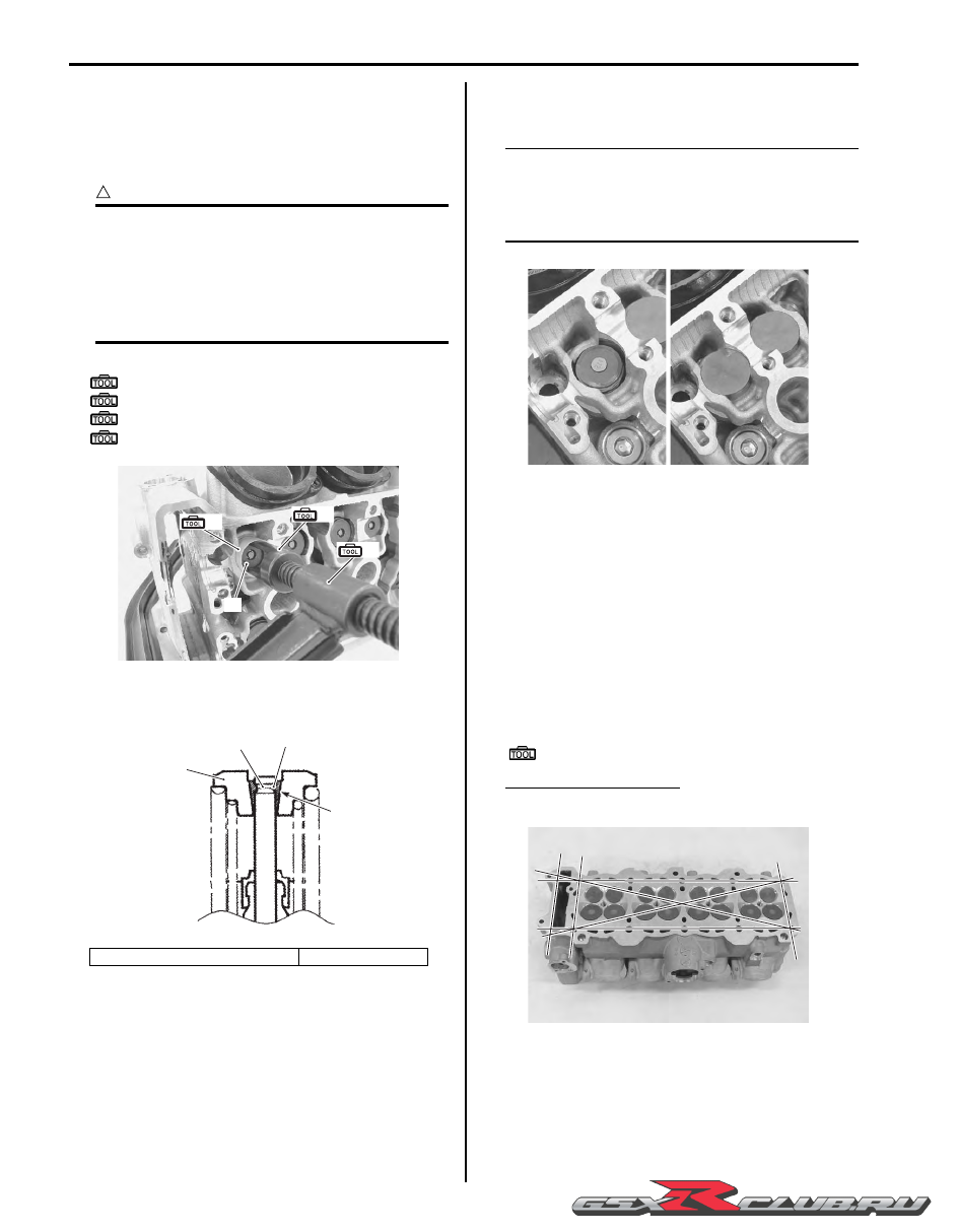
Cylinder Head Distortion

1) Decarbonize the combustion chambers.

2) Check the gasket surface of the cylinder head for 

distortion. Use a straightedge and thickness gauge. 
Take clearance readings at several places. If 
readings exceed the service limit, replace the 
cylinder head.

Special tool

:  09900–20803 (Thickness gauge)

Cylinder head distortion
Service limit: 0.02 mm (0.0008 in)

10. Valve spring retainer

11. Cotter

(A)

(B)

(C)

10

I947H1140089-01

“H”

10

11

“G”

I947H1140090-02

I947H1140091-01

I947H1140092-02

-------------------------------------------------------------------------------------------------------------------------------------------------------------

Engine Mechanical:  1D-45

Valve Stem Runout

Support the valve using V-blocks, as shown in the figure, 
and check its runout using the dial gauge. If the runout 
exceeds the service limit, replace the valve.

Special tool

(A):  09900–20607 (Dial gauge)
(B):  09900–20701 (Dial gauge chuck)
(C):  09900–21304 (V blocks)

Valve stem runout (IN. & EX.)
Service limit: 0.05 mm (0.002 in)

Valve Head Radial Runout

Place the dial gauge at a right angle to the valve head 
face and measure the valve head radial runout. If it 
measures more than the service limit, replace the valve.

Special tool

(A):  09900–20607 (Dial gauge)
(B):  09900–20701 (Dial gauge chuck)
(C):  09900–21304 (V blocks)

Valve head radial runout (IN. & EX.)
Service limit: 0.03 mm (0.001 in)

Valve Stem and Valve Face Wear Condition

Visually inspect each valve stem and valve face for wear 
and pitting. If it is worn or damaged, replace the valve 
with a new one.

Valve Stem Deflection

Lift the valve about 10 mm (0.39 in) from the valve seat. 
Measure the valve stem deflection in two directions, “X” 
and “Y”, perpendicular to each other. Position the dial 
gauge as shown. If the deflection exceeds the service 
limit, then determine whether the valve or the guide 
should be replaced with a new one.

Special tool

(A):  09900–20607 (Dial gauge)
(B):  09900–20701 (Dial gauge chuck)

Valve stem deflection (IN. & EX.)
Service limit: 0.25 mm (0.010 in)

(A)

(C)

(B)

I649G1140231-03

(A)

(B)

(C)

I649G1140232-03

I947H1140093-01

(A)

(B)

I837H1140061-03

-------------------------------------------------------------------------------------------------------------------------------------------------------------

1D-46 Engine Mechanical: 

Valve Stem Wear

Measure the valve stem O.D. using the micrometer. If it 
is out of specification, replace the valve with a new one. 
If the valve stem O.D. is within specification but the valve 
stem deflection is not, replace the valve guide. After 
replacing the valve or valve guide, recheck the 
deflection.

Special tool

(A):  09900–20205 (Micrometer (0 – 25 mm))

Valve stem O.D.
Standard (IN.): 4.475 – 4.490 mm (0.1762 – 0.1768 in)
Standard (EX.): 4.455 – 4.470 mm (0.1754 – 0.1760 in)

NOTE

If valve guides have to be removed for 
replacement after inspecting related parts, 
carry out the steps shown in valve guide 
replacement. Refer to “Valve Guide 
Replacement” (Page 1D-47)
.


Valve Spring

The force of the coil springs keep the valve seat tight. A 
weakened spring results in reduced engine power output 
and often accounts for the chattering noise coming from 
the valve mechanism.
Check the valve springs for proper strength by 
measuring their free length and also by the force 
required to compress them. If the spring length is less 
than the service limit or if the force required to compress 
the spring does not fall within the specified range, 
replace both the inner and outer springs as a set.

Special tool

(A):  09900–20102 (Vernier calipers (200 mm))

Valve spring free length (IN. & EX.)
Service limit: Inner: 30.1 mm (1.19 in)
Service limit: Outer: 35.3 mm (1.39 in)

Valve spring tension (IN. & EX.)
Standard: Inner: 31.3 – 38.3 N (3.2 – 3.9 kgf, 7.0 – 8.6 
lbs)/27.55 mm (1.085 in)
Standard: Outer: 91.3 – 105.1 N (9.3 – 10.7 kgf, 20.5 – 
23.6 lbs)/33.05 mm (1.301 in)

Valve Seat Width

1) Visually check for valve seat width on each valve 

face. If the valve face has worn abnormally, replace 
the valve.

2) Coat the valve seat with a red lead (Prussian Blue) 

and set the valve in place.

CAUTION

!


Do not use lapping compound.


3) Rotate the valve with light pressure.

Special tool

(A):  09916–10911 (Valve lapper set)

(A)

I718H1140122-01

Tension “a”

Length “b”

Inner

31.3 – 38.3 N 

(3.2 – 3.9 kgf, 7.0 – 8.6 lbs)

27.55 mm 

(1.085 in)

Outer

91.3 – 105.1 N 

(9.3 – 10.7 kgf, 20.5 – 23.6 lbs)

33.05 mm 

(1.301 in)

(A)

I649G1140237-03

“ a ”

“ b ”

I649G1140238-03

(A)

I947H1140094-01

-------------------------------------------------------------------------------------------------------------------------------------------------------------

Engine Mechanical:  1D-47

4) Check that the transferred red lead (blue) on the 

valve face is uniform all around and in center of the 
valve face.
If the seat width “a” measured exceeds the standard 
value, or seat width is not uniform reface the seat 
using the seat cutter. Refer to “Valve Seat Repair” 
(Page 1D-49).

Valve seat width “a” (IN. & EX.)
Standard: 0.9 – 1.1 mm (0.035 – 0.043 in)

Valve Seat Sealing Condition

1) Clean and assemble the cylinder head and valve 

components.

2) Fill the intake and exhaust ports with gasoline to 

check for leaks. If any leaks occur, inspect the valve 
seat and face for burrs or other things that could 
prevent the valve from sealing. Refer to “Valve Seat 
Repair” (Page 1D-49).

WARNING

!


Always use extreme caution when handling 
gasoline.


NOTE

After servicing the valve seats, be sure to 
check the valve clearance after the cylinder 
head has been reinstalled. Refer to “Valve 
Clearance Inspection and Adjustment” in 
Section 0B (Page 0B-5).


Valve Guide Replacement

B947H11406029

1) Remove the cylinder head. Refer to “Engine Top 

Side Disassembly” (Page 1D-26).

2) Remove the valves. Refer to “Cylinder Head 

Disassembly and Assembly” (Page 1D-40).

3) Using the valve guide remover, drive the valve guide 

out toward the intake or exhaust camshaft side.

Special tool

(A):  09916–43211 (Valve guide installer & 

remover)

NOTE

• Discard the removed valve guide sub-

assemblies.

• Only oversized valve guides are available 

as replacement parts. (Part No. 11115-
29G70)


4) Refinish the valve guide holes in the cylinder head 

using the reamer and handle.

CAUTION

!


When refinishing or removing the reamer 
from the valve guide hole, always turn it 
clockwise.


Special tool

(B):  09916–33320 (Valve guide reamer (9.8 

mm))

(C):  09916–34542 (Reamer handle)

“a”

I649G1140246-02

I947H1140095-01

(A)

I947H1140096-01

(B)

(C)

I947H1140097-01

-------------------------------------------------------------------------------------------------------------------------------------------------------------

1D-48 Engine Mechanical: 

5) Cool down the new valve guides in a freezer for 

about one hour and heat the cylinder head to 100 – 
150 

°

C (212 – 302 

°

F) with a hot plate.

CAUTION

!


Do not use a burner to heat the valve guide 
hole to prevent cylinder head distortion.


6) Apply engine oil to each valve guide and valve guide 

hole.

7) Drive the guide into the guide hole using the valve 

guide installer.

CAUTION

!


Failure to oil the valve guide hole before 
driving the new guide into place may result in 
a damaged guide or head.


Special tool

(A):  09916–43211 (Valve guide installer & 

remover)

(D):  09916–53380 (Valve guide installer 

attachment)

8) After installing the valve guides, refinish their guiding 

bores using the reamer. Be sure to clean and oil the 
guides after reaming.

NOTE

• Be sure to cool down the cylinder head to 

ambient air temperature.

• Insert the reamer from the combustion 

chamber and always turn the reamer 
handle clockwise.


Special tool

(C):  09916–34542 (Reamer handle)
(E):  09916–33210 (Valve guide reamer (4.5 

mm))

9) Reassemble the cylinder head. Refer to “Cylinder 

Head Disassembly and Assembly” (Page 1D-40).

10) Install the cylinder head assembly. Refer to “Engine 

Top Side Assembly” (Page 1D-28).

1. Cylinder head

“a”: 13.7 – 13.9 mm (0.54 – 0.55 in) 

[IN and EX]

“ a ”

(A)

(D)

1

I838H1140077-01

(A)

(D)

I947H1140098-01

(C)

(E)

I947H1140099-01

-------------------------------------------------------------------------------------------------------------------------------------------------------------

Engine Mechanical:  1D-49

Valve Seat Repair

B947H11406030

The valve seats (1) for both the intake and exhaust 
valves are machined to three different angles. The seat 
contact surface is cut at 45

°

.

CAUTION

!


• The valve seat contact area must be 

inspected after each cut.

• Do not use lapping compound after the 

final cut is made. The finished valve seat 
should have a velvety smooth finish but 
not a highly polished or shiny finish. This 
will provide a soft surface for the final 
seating of the valve which will occur 
during the first few seconds of engine 
operation.

• The titanium valves are coated with an 

oxidized membrane treatment to resist 
wear but the membrane tend to removed if 
lapped after valve seat servicing.


NOTE

After servicing the valve seats, be sure to 
check the valve clearance after the cylinder 
head has been reinstalled. Refer to “Valve 
Clearance Inspection and Adjustment” in 
Section 0B (Page 0B-5).


Engine Bottom Side Disassembly

B947H11406031

NOTE

The crankcase must be separated to service 
the crankshaft and conrod.


1) Remove the engine assembly from the frame. Refer 

to “Engine Assembly Removal” (Page 1D-20).

2) Remove the engine top side (1). Refer to “Engine 

Top Side Disassembly” (Page 1D-26).

Crankcase Breather (PCV) Cover

Remove the crankcase breather (PCV) cover (1).

Starter Motor

Remove the starter motor (1).

Clutch

Remove the clutch component parts (1). Refer to “Clutch 
Removal” in Section 5C (Page 5C-5).

[A]: Intake valve

[B]: Exhaust valve

Intake

Exhaust

Seat angle

30

°

/45

°

/60

°

15

°

/45

°

/60

°

Seat width

0.9 – 1.1 mm 

(0.035 – 0.043 in)

Valve 

diameter

31.0 mm 

(1.22 in)

25.0 mm 

(0.98 in)

Valve guide 

I.D.

4.500 – 4.512 mm 

(0.1772 – 0.1776 in)

60

q

1

45

q

15

q

60

q

45

q

30

q

1

[A]

[B]

I837H1140069-01

1

I947H1140107-02

1

I947H1140108-03

1

I947H1140109-01

-------------------------------------------------------------------------------------------------------------------------------------------------------------

1D-50 Engine Mechanical: 

Gearshift System

Remove the gearshift shaft (1) and gearshift cam plate 
(2). Refer to “Gearshift Shaft / Gearshift Cam Plate 
Removal and Installation” in Section 5B (Page 5B-17).

Starter Torque Limiter / Starter Clutch

Remove the starter torque limiter (1) and starter clutch 
(2) component parts. Refer to “Starter Torque Limiter 
Removal and Installation” in Section 1I (Page 1I-9) 
and 
“Starter Clutch Removal and Installation” in Section 1I 
(Page 1I-10)
.

Cam Chain / Cam Chain Tensioner / Cam Chain 
Guide No. 1

1) Remove the washer (1).

2) Remove the cam chain tensioner (2) and cam chain 

guide No. 1 (3).

3) Remove the cam chain drive sprocket (4) and cam 

chain (5).

Generator

Remove the generator cover (1) and rotor. Refer to 
“Generator Removal and Installation” in Section 1J 
(Page 1J-4).

Water Pump

1) Remove the water inlet connector (1).

1

2

I947H1140110-02

1

2

I947H1140111-02

1

I947H1140112-01

2

3

5

4

I947H1140113-02

1

I947H1140114-01

1

I947H1140115-01

-------------------------------------------------------------------------------------------------------------------------------------------------------------

Engine Mechanical:  1D-51

2) Remove the water pump (2).

Gear Position Switch

Remove the gear position switch (1).

Oil Pressure Switch

Remove the oil pressure switch lead wire (1) and switch 
(2).

Oil Filter

Remove the oil filter (1) with the special tool.

Special tool

(A):  09915–40610 (Oil filter wrench)

Oil Pan

1) Remove the plate (1).

2) Remove the oil pan (2) and gasket.

Oil Pressure Regulator / Oil Strainer

1) Remove the oil pressure regulator (1).

2) Remove the oil strainer (2).

3) Remove the O-ring (3).

2

I947H1140116-01

1

I947H1140117-01

1

2

I947H1140118-01

(A)

1

I947H1140119-01

1

2

I947H1140297-01

1

2

I947H1140121-01

3

I947H1140122-01

-------------------------------------------------------------------------------------------------------------------------------------------------------------

1D-52 Engine Mechanical: 

Oil Pump

1) Remove the spacer (1) and bearing (2).

2) Remove the oil pump drive sprocket (3) and chain 

(4).

3) Remove the thrust washer (5).

4) Remove the oil pump assembly (6).

5) Remove the dowel pins and O-ring (7).

6) Remove the breather oil return pipe (8).

Crankcase

1) Remove the clutch push rod oil seal retainer (1).

2) Remove the cap (2).

3) Remove the crankcase bolts from upper side.

NOTE

Loosen the crankcase bolts diagonally and 
smaller size ones first.


4) Remove the crankcase bolts from lower side.

1

2

I947H1140126-01

3

5

4

I947H1140127-01

6

7

I947H1140128-02

8

I947H1140129-02

1

I947H1140123-01

2

I947H1140124-02

I947H1140125-02

-------------------------------------------------------------------------------------------------------------------------------------------------------------

Engine Mechanical:  1D-53

5) Remove the crankshaft journal bolts (M9).

6) Make sure that all of the bolts are removed. Then, 

tap the sides of the lower crankcase using a plastic 
hammer to separate the upper and lower crankcase 
halves and then lift the lower crankcase off the upper 
crankcase.

7) Remove the dowel pins and O-rings (3).

Balancer Shaft

Remove the balancer shaft assembly (1) and plug (2).

Transmission

Remove the transmission component. Refer to 
“Transmission Removal” in Section 5B (Page 5B-3).

Crankshaft

1) Loosen the conrod cap bolts using a 10 mm, 12-

point socket wrench.

2) Remove the conrod caps by tapping the bolts lightly 

with a plastic hammer.

I947H1140130-01

3

I947H1140131-04

1

2

I947H1140132-01

I947H1140133-01

I947H1140134-01

I947H1140135-01

I947H1140136-01

-------------------------------------------------------------------------------------------------------------------------------------------------------------

1D-54 Engine Mechanical: 

3) Remove the crankshaft (1) and thrust bearings (2).

Piston Cooling Oil Jet

Remove the piston cooling oil jet (1) from the upper 
crankcase.

Piston / Conrod

1) Push the conrod to cylinder head side and remove 

the piston and conrod from the upper crankcase.

CAUTION

!


Be careful not to damage the cylinder wall by 
the conrod.


2) Remove the piston pin circlip (1).

3) Draw out the piston pin (2) and remove the piston 

from the conrod.

NOTE

Scribe the cylinder number on the piston 
head.


1

2

I947H1140137-01

1

I947H1140138-01

I947H1140139-02

I947H1140140-01

1

I947H1140141-01

2

I947H1140142-01

-------------------------------------------------------------------------------------------------------------------------------------------------------------

Engine Mechanical:  1D-55

Crankshaft Journal Bearing

Remove the crankshaft journal bearings, upper and 
lower.

CAUTION

!


• When removing the crankshaft journal 

bearings, be careful not to scratch the 
crankcase and the crankshaft journal 
bearings.

• Do not touch the bearing surfaces with 

your hands. Grasp the bearings by their 
edges.


NOTE

• Do not remove the crankshaft journal 

bearings unless absolutely necessary.

• Make a note of where the crankshaft 

journal bearings are removed from so that 
they can be reinstalled in their original 
positions.


Oil Jet

Remove the oil jet (1) (for transmission) from the lower 
crankcase.

Oil Gallery Plug

1) Remove the oil gallery plug (1), (2) and (3) from the 

lower crankcase.

I947H1140143-01

I947H1140144-01

1

I947H1140145-01

1

I947H1140146-01

2

I947H1140147-01

3

I947H1140148-01

-------------------------------------------------------------------------------------------------------------------------------------------------------------

1D-56 Engine Mechanical: 

2) Remove the oil gallery plug (4) from the upper 

crankcase.

Water Jacket Plug

Remove the water jacket plugs (1) from the upper 
crankcase.

Oil Seal / Bearing

Remove the oil seal and bearings if necessary. Refer to 
“Transmission Removal” in Section 5B (Page 5B-3).

Breather Oil Return Plate

Remove the breather oil return plate (1) from the upper 
crankcase.

Engine Bottom Side Assembly

B947H11406032

Assemble the engine bottom side in the reverse order of 
disassembly. Pay attention to the following points:

NOTE

Apply engine oil to each running and sliding 
part before reassembling.


Breather Oil Return Plate

When installing the breather oil return plate (1), apply 
thread lock to the bolts.

:  Thread lock cement 99000–32110 (THREAD 

LOCK CEMENT SUPER “1322” or equivalent)

Oil Seal / Bearing

Install the oil seal and bearings. Refer to “Transmission 
Installation” in Section 5B (Page 5B-5).

Water Jacket Plug

• Apply engine coolant to the O-rings of the water jacket 

plugs.

4

I947H1140149-01

1

1

I947H1140150-01

I947H1140151-01

I947H1140152-01

1

I947H1140153-01

1

I947H1140154-01

-------------------------------------------------------------------------------------------------------------------------------------------------------------

Engine Mechanical:  1D-57

• Tighten each plug to the specified torque.

CAUTION

!


Replace the O-rings with new ones.


Tightening torque
Water jacket plug (a):  9.5 N·m (0.95 kgf-m, 6.9 lbf-
ft)

Oil Gallery Plug

CAUTION

!


Replace the gaskets with new ones.


• Apply thread lock to the oil gallery plug (M10) and 

tighten it to the specified torque.

:  Thread lock cement 99000–32110 

(THREAD LOCK CEMENT SUPER “1322” or 
equivalent)

Tightening torque
Oil gallery plug (M10) (a):  18 N·m (1.8 kgf-m, 13.0 
lbf-ft)

• Apply thread lock to the oil gallery plug (M12) and 

tighten it to the specified torque.

:  Thread lock cement 99000–32110 

(THREAD LOCK CEMENT SUPER “1322” or 
equivalent)

Tightening torque
Oil gallery plug (M12) (b):  15 N·m (1.5 kgf-m, 11.0 
lbf-ft)

• Tighten the oil gallery plugs to the specified torque.

Tightening torque
Oil gallery plug (M26) (c):  11 N·m (1.1 kgf-m, 8.0 
lbf-ft)
Oil gallery plug (M6) (d):  10 N·m (1.0 kgf-m, 7.0 
lbf-ft)

Oil Jet

Install the oil jet (1) (for transmission).

(a)

(a)

I947H1140155-01

(a)

I947H1140156-01

(b)

I947H1140157-01

(c)

I947H1140159-01

(d)

I947H1140158-01

1

I947H1140160-01

-------------------------------------------------------------------------------------------------------------------------------------------------------------

1D-58 Engine Mechanical: 

Crankshaft Journal Bearing

When fitting the crankshaft journal bearings to the upper 
and lower crankcases, be sure to fix the stopper part “A” 
first and press the other end.

CAUTION

!


Do not touch the bearing surfaces with your 
hands. Grasp by the edge of the bearing 
shell.


NOTE

Inspect and select the crankshaft journal 
bearing if necessary. Refer to “Crankshaft 
Journal Bearing Inspection and Selection” 
(Page 1D-79).


Piston and Conrod

• Apply a small quantity of molybdenum oil solution 

onto each piston pin.

M/O:  Molybdenum oil  (MOLYBDENUM OIL 
SOLUTION)

• Assemble the piston and conrod.

NOTE

When installing the pistons, the indent “A” 
on the piston head must be brought to the 
other side of ID code “B” on the conrod big 
end.


• Install the piston pin circlips (1).

CAUTION

!


Use new piston pin circlips (1) to prevent 
circlip failure which will occur when it is bent.


NOTE

End gap of the circlip “C” should not be 
aligned with the cutaway in the piston pin 
bore.


• Apply a small quantity of molybdenum oil solution to 

the sliding surface of the pistons and cylinder walls.

M/O:  Molybdenum oil  (MOLYBDENUM OIL 
SOLUTION)

NOTE

Be sure to install the pistons in the cylinders 
from which they were removed in 
disassembly, referring to the cylinder 
numbers, #1 through #4, scribed on the 
piston.


“A”

I947H1140161-01

“A”

“B”

I947H1140162-01

1

“C”

I947H1140163-01

I947H1140164-01

-------------------------------------------------------------------------------------------------------------------------------------------------------------

Engine Mechanical:  1D-59

• Install the pistons with conrods into the cylinders from 

topside using the special tool.

NOTE

When installing the pistons, the indent “D” of 
each piston head must be brought to the 
exhaust side.


Special tool

(A):  09916–77310 (Piston ring compressor)

• Check that I.D. code “E” on each conrod faces intake 

side.

CAUTION

!


Be sure to clean the conrod big end.


Piston Cooling Oil Jet

• Fit new O-ring (1) to each piston cooling oil jet and 

apply engine oil to it.

CAUTION

!


Use new O-ring to prevent oil pressure 
leakage.


• Install each piston cooling oil jet.

NOTE

Apply a small quantity of thread lock to the 
bolts and tighten them to the specified 
torque.


:  Thread lock cement 99000–32110 

(THREAD LOCK CEMENT SUPER “1322” or 
equivalent)

Tightening torque
Piston cooling oil jet bolt (a):  10 N·m (1.0 kgf-m, 
7.0 lbf-ft)

Crankshaft

1) Apply molybdenum oil to each crank pin bearing 

surface and crankshaft journal bearing surface.

M/O:  Molybdenum oil  (MOLYBDENUM OIL 
SOLUTION) 

(A)

“D”

I947H1140165-01

“E”

I947H1140166-01

1

I947H1140167-01

(a)

I947H1140168-02

I947H1140169-01

-------------------------------------------------------------------------------------------------------------------------------------------------------------


Content      ..     16      17      18      19     ..