CFMoto ATV CF500-A 4x4. Service Manual - part 7


  Index      Manuals     CFMoto ATV CF500-A 4x4. Service Manual


Search            copyright infringement  


Content      ..     5      6      7      8     ..


CFMoto ATV CF500-A 4x4. Service Manual - part 7


After riding in water deep enough to allow it to enter the 
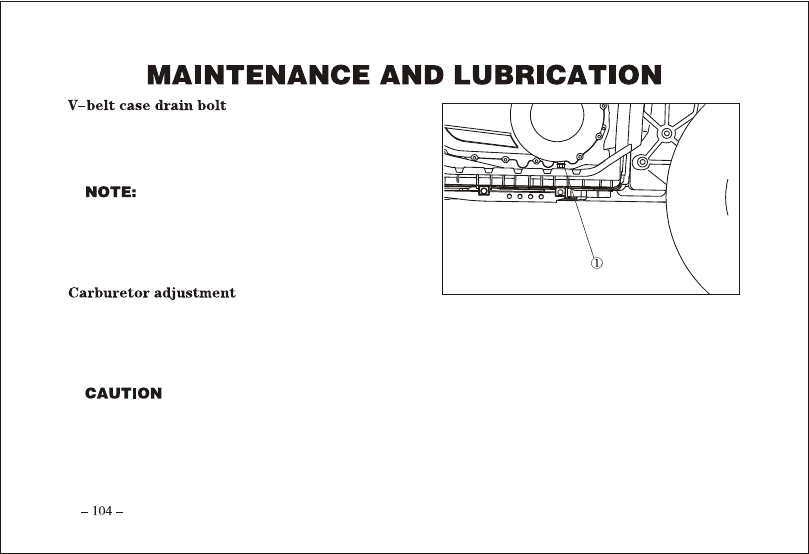
V-belt case, remove this bolt to drain the water from the 
case.

 If water drains from the V-belt case after 

removing the bolt, have your dealer inspect 
the ATV as the water may affect other engine 
parts.

The carburetor is a vital part of the engine and requires very sophisticated adjustment. Most adjusting should be 
left to your dealer who has the professional knowledge and experience to do so. However, the idling speed may 
be performed by the owner as a part of the usual maintenance routine.

The carburetor was set at the factory after many tests. If the settings are disturbed by someone without 
sufficient technical knowledge, poor engine performance and damage may result.

-------------------------------------------------------------------------------------------------------------------------------------------------------------

 A diagnostic tachometer must be used for this procedure.

1. Start the engine and warm it up for a few minutes at approximately 1,000 to 2,000r/min. Occasionally rev the 

engine to 4,000 to 5,000 r/min. The engine is warm when it 
quickly responds to the throttle.

2. Remove panel.
3. Connect the tachometer to the spark plug lead, and then set 

the idle to the specified idling speed by adjusting the throttle 
stop screw. Turn the screw in direction     to increase the 
engine speed, and in direction     to decrease the engine 
speed.

 Specified idle speed:1,200

1,400 r/min

4. Install the panel.

The correct valve clearance changes with use, resulting in improper fuel/air supply or engine noise. To prevent 
this, the valve clearance must be adjusted regularly. This adjustment however, should be left to a professional 
service technician.

a

b

-------------------------------------------------------------------------------------------------------------------------------------------------------------

Adjust the engine idling speed before adjusting 

the throttle lever free play.

1. Loosen the locknut.
2. Turn the adjusting bolt until the throttle lever free play is 

3

5 mm (0.12

0.20 in).

3. Tighten the locknut.

Check the brake pads for damage and wear.
If a brake pad thickness is less than 2 mm (0.08 in), have 
your dealer replace the pads as a set.

The wheels need to be removed to check the 

brake pads.

-------------------------------------------------------------------------------------------------------------------------------------------------------------

Inspect the brake pads for damage and wear.
If the thickness is less than 4 mm(0.16 in), have your dealer 
replace the pads.

Insufficient brake fluid may let air enter the brake system, 
possibly causing the brakes to become ineffective. Before riding, 
check that the brake fluid is above the lower level and replenish when necessary. The front brake fluid master 
cylinder reservoir is located the right of the handlebar. The rear brake fluid master cylinder reservoir is near the 
rear brake pedal.

-------------------------------------------------------------------------------------------------------------------------------------------------------------

Observe these precautions:
1. When checking the fluid level,  make sure the top of the master cylinder reservoir is level by turning the 

handlebars.

2. Use only the designated quality brake fluid. Otherwise, the rubber seals may deteriorate, causing leakage and 

poor brake performance.

Recommended brake fluid: DOT3 or DOT 4.

3. Refill with the same type of brake fluid.  Mixing fluids may result in a harmful chemical reaction and lead to 

poor brake performance.

4. Be careful that water does not enter the master cylinder reservoir when refilling.  Water will significantly 

lower the boiling point of the fluid and may result in vapor lock.

5. Brake fluid may deteriorate painted surfaces or plastic parts. Always clean up spilled fluid immediately.
6. Have your dealer check the cause if the brake fluid level goes down.

-------------------------------------------------------------------------------------------------------------------------------------------------------------

Complete fluid replacement should be done only by trained service personnel. Have your dealer replace the 
following components during periodic maintenance or when they are damaged or leaking.

 Replace the oil seals every two years.

 Replace the brake hoses every four years.

The front brake lever should have a free play of zero mm (zero in) at the lever end. If not, have your dealer 
check the brake system.

 After servicing:

 Make sure the brakes operate smoothly and that the 

free play is correct.

 Make sure the brakes do not drag.

Make sure the brakes are not spongy.

 All air must be bled from the brake system.

Replacement of brake components requires professional knowledge. These procedures should be performed 
by your dealer.

-------------------------------------------------------------------------------------------------------------------------------------------------------------

The rear brake lever free play       should be 0.5

2 mm 

(0.02

0.08 in).

1. Loosen the locknut

.

2. Turn the adjusting bolt

 in direction       to increase 

free play, and in direction         to decrease free play.

3. Tighten the locknut

.

If correct free play cannot be obtained, ask your dealer to 
make that adjustment.

  When adjusting the rear brake lever free play:

 Be sure not to step on the brake pedal.

 Make sure the brake pedal does not move.

 Adjust the rear brake before inspecting the rear brake pads.

a

b

c

-------------------------------------------------------------------------------------------------------------------------------------------------------------

The top of the brake pedal should be positioned 72mm (2.8 in) 
above the top of the footrest. If not, ask your dealer to adjust it.

After servicing:

 Make sure the brakes operate smoothly and that the free 

play is correct.

 Make sure the brakes do not drag.

 All air must be bled from the brake system.

Replacement of brake components requires professional knowledge. These procedures should be performed 
by your dealer.

The rear brake light switch, which is activated by the brake 
pedal and brake levers, is properly adjusted when the brake 
light comes on just before braking takes effect. If necessary, 
adjust the brake light switch as follows.

-------------------------------------------------------------------------------------------------------------------------------------------------------------

Turn the adjusting nut while holding the rear brake light switch in place. To make the brake light come on 
earlier, turn the adjusting nut in direction     . To make the brake light come on later, turn the adjusting nut in 
direction      .

Inspect cables frequently. Replace damaged cables.

Lubricate the inner cables and the cable ends. If the cables do not operate smoothly, ask your dealer to replace 
them.

 Recommended lubricant: SAE 10W30 motor oil

Lubricate the knuckle upper and lower pivots with a grease 
gun.

Recommended lubricant:

Lithium-soap-based grease

a

b

-------------------------------------------------------------------------------------------------------------------------------------------------------------

1. Loosen the wheel nuts.
2. Elevate the ATV and place a suitable stand under the frame.
3. Remove the nuts from the wheel.
4. Remove the wheel.

1. Install the wheel and the nuts.

 Tapered nuts are used for both the front and rear 

wheels. Install the nut with its tapered side towards the wheel. 

 The arrow        mark on the tire must point toward the rotating direction of the wheel.

-------------------------------------------------------------------------------------------------------------------------------------------------------------

2. Lower the ATV so that the wheel is on the ground.
3. Tighten the wheel nuts to the specified torque.

 Wheel nut torque: Front: 55 N m ( 5.5 m


kgf, 40  ft  lbf). Re ar: 55 N   m (5.5  m  kgf, 40 ft  lb f)

This machine is equipped with a sealed-type battery. Therefore it is not necessary to check the electrolyte or 
add distilled water in the battery. If the battery seems to have discharged, consult your dealer.

Do not try to remove the sealing caps of the battery cells. You may damage the battery.

Avoid contact with skin, eyes or clothing. Always shield eyes when working near batteries. Keep out of 
reach of children.

Antidote:
EXTERNAL: Flush with water. INTERNAL: Drink large quantities of water or milk. Follow with milk of 
magnesia, beaten egg or vegetable oil.  Get prompt medical attention.
EYES: Flush with water for 15 minutes and get prompt medical attention. Keep batteries away from sparks, 
flames, cigarettes or other sources of ignition. Ventilate when charging or using in a closed space.

-------------------------------------------------------------------------------------------------------------------------------------------------------------

1. When the machine is not used for a month or longer, remove the battery and store it in a cool, dark place. 

Completely recharge the battery before reinstallation.

A special battery charger (constant voltage/ampere or constant voltage) is required for recharging a sealed-
type battery. Using a conventional battery charger may shorten 
the battery life.

2. Always make sure the connections are correct when putting the 
battery back in the machine.

1. The main fuse case and the fuse box are located under the seat.
2. If a fuse is blown, turn off the main switch and install a new 

fuse of the specified amperage. Then turn on the switches. If 
the fuse immediately blows again, consult your dealer.

Always use a fuse of the specified rating.
Never use a material in place of the proper fuse.

-------------------------------------------------------------------------------------------------------------------------------------------------------------

To prevent accidental short-circuiting, turn off the main switch 

when checking or replacing a fuse.

If a headlight bulb burns out, replace it as follows:
1. Remove the bolts

 and pulling headlight cover

 off.

2. Remove the rubber cover at the rear of the headlight by pulling 

it off.

3. Remove the headlight lock spring.
4. Pull headlight bulb out from the headlight bulb holder.

 Wait for the bulb to cool before touching or removing it.

-------------------------------------------------------------------------------------------------------------------------------------------------------------

5. Insert a new headlight bulb into the headlight bulb holder, 

and then lock it by spring.

6. Install the bulb holder by turning it clock-wise.
7. Install the rubber cover at the rear of the headlight.
8. Install the headlight cover with the bolts.

It is advisable to have your dealer make this adjustment.

Turn the adjusting screws

 can raise or lower the beam.

-------------------------------------------------------------------------------------------------------------------------------------------------------------

If the tail/brake light bulb burns out, replace it as follows:
1. Remove the screws

, and then pull tail/brake light cover

 out.

2. Remove the tail/brake light bulb by pushing it in and turning it counter-clockwise.
3. Insert a new tail/brake light bulb, push it in, and the turning it clockwise.
4. Install the tail/brake light cover with the screws.

-------------------------------------------------------------------------------------------------------------------------------------------------------------

The spring preload can be adjusted to suit the rider s weight 

and riding conditions.

When adjusting the rear shock absorbers, the 

rear wheels need to be removed.

Adjust the spring preload as follows.
To increase the spring preload, turn the adjusting ring in 
direction      .
To decrease the spring preload, turn the ad-justing ring in 
direction       .

A special wrench can be obtained at a dealer to 

make this adjustment.

Standard position: B
A- Minimum (soft)
E- Maximum (hard)

Always adjust the shock absorbers on the left and right 
side to the same setting.

a

b

-------------------------------------------------------------------------------------------------------------------------------------------------------------


Content      ..     5      6      7      8     ..