CFMoto motorcycle CF150-A. Service Manual - part 8


  Index      Manuals     CFMoto motorcycle CF150-A. Service Manual


Search            copyright infringement  


Content      ..     6      7      8      9     ..


CFMoto motorcycle CF150-A. Service Manual - part 8


7-4

CFMOTO

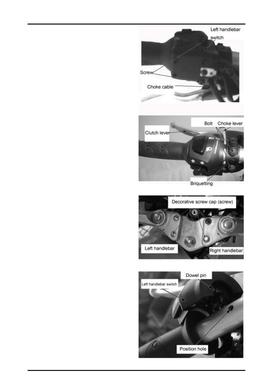
Loosen 2 pcs mounting screw,

Seperate choke cable and choke lever,

remove left handlebar switch

Loosen 2 pcs briquetting bolt,clutch lever,

remove clutch lever

Loosen 4pcs decorative screw cap(disposable items)

with straight screwdriver,remove 4 pcs fixing screw

and left handlebar.

Installation

reverse the disassembly procedure for installation.

Insert dowel pin into position hole when assembling

left handlebar.

-------------------------------------------------------------------------------------------------------------------------------------------------------------

Front wheel,Braking,Suspension  and Steering System

 7

7

7

7

7

7-5

When assembling right handlebar switch,

insert throttle grip into right handlebar,

install throttle cable.

Insert dowel pin into position hole, assemble

right handlebar.

-------------------------------------------------------------------------------------------------------------------------------------------------------------

7-6

CFMOTO

Front Wheel

Support main stand,put a jack under engine or put a

heavy thing on rack, raise  front wheel.

Loosen

-cable, speedometer

-nut, front wheel shaft

Remove

-front wheel shaft

-front wheel

Front wheel shaft inspection

Put front wheel shaft on V block,

check curvature.

service limit: >0.2mm

¡ú

replace

Front rim inspection

Put front wheel on turntable, turn wheel to check wheel

beating with dial indicator..

Service limit:

Axial direction: 2.0mm

Radial direction: 2.0mm

Check wheel bearing for looseness; turn bearing inner

ring to check for flexible rotation; Check if any loose-

ness when assembled on rim.

If any above problem, replace with a new bearing.

-------------------------------------------------------------------------------------------------------------------------------------------------------------

Front wheel,Braking,Suspension  and Steering System

 7

7

7

7

7

7-7

Disassembly

Remove counter from right side of front wheel

Remove:

-sleeve, front wheel shaft

-4pcs fising bolt

-brake disc

-front disc brake disc

-dust seal

thickness service llimit, front disc brake disc: 3mm

Push out wheel bearing and wheel shaft sleeve

-------------------------------------------------------------------------------------------------------------------------------------------------------------

7-8

CFMOTO

Installation

Apply grease to bearing inner ring,

press fitting bearing and shaft sleeve.

NOTE

Press fitting right bearing,front wheel before left breaing.

Install front brake disc,lock up bolt with retainer,

apply grease to dust seal before intalling to

brake disc side of front wheel,

install sleeve, front wheel shaft.

Install counter to wheel,

set jag into groove.

Install front wheel to front shock absorber,

insert front wheel shaft from left to right

with nut,install speedometer cable to

counter through cable clip.

UP in counter points to lock nut,front wheel

shaft in shock absorber direction.

tightening nut£¬front wheel shaf

t

£º

60-80N

¡¤

m

NOTE

NOTE

NOTE

NOTE

NOTE

Make sure cable is in line with counter when assem-

bling cable, speedometer..

-------------------------------------------------------------------------------------------------------------------------------------------------------------

Front wheel,Braking,Suspension  and Steering System

 7

7

7

7

7

7-9

Front shock absorber

Remove

front fender-(2-7)

big light cover-(¨2-8)

front wheel-(7-6)

Loosen

-2 pcs fixing bolt

-2pcs fixing screw 1

Loosen 4 pcs fixing screw, remove handlebar(LH&RH).

Loosen 2 pcs fixing bolt, brake disc

Remove front shock absorber(LH&RH).

NOTE

Do not put the shock absorber upside down in

case of oil leakage from inner absorber.

Inspection:

Oil leakage, aged or damaged oil seal 

-

Replace

Installation

Reverse removal procedure for

installation.

Set brake hose into brake clipper, apply

thread glue to fixing bolt,brake disc, tight-

ening torque:30-40N

.

m

Fastening screw 1: 20-30N

.

m

Fixing bolt: 30-40 N

.

m

Fastening screw: 10-14N

.

m

-------------------------------------------------------------------------------------------------------------------------------------------------------------

7-10

CFMOTO

Steering Column

Remove:

front fender

-(

2-7

)

big light cover

-(

2-8

)

front wheel

-(

7-6

)

handlebar

(

LH&RH

)-(

7-9

)

front shock absorber

-(

7-9

)

2 pcs bolt, loosen dashboard

Loosen fixing bolt

Loosen nut with wrench, remove dust cover and lower

joint plate, front fork.

Remove circlip, upper bearing, top and bottom ball.

Remove top and bottom bearing race with impact tool.

-------------------------------------------------------------------------------------------------------------------------------------------------------------

Front wheel,Braking,Suspension  and Steering System

 7

7

7

7

7

7-11

Installation

Put bottom ball into lower joint plate, front fork.

Install top and bottom bearing race to frame riser with

impact tool, apply enough grease.

Put top ball into top bearing race.

Install lower joint plate to frame riser,

insert top bearing race and dust cover.

Lock up lower jont plate with nut, adjust tightness to

proper position(standard:plate do not move up and

down, flexible move left and right)

lock up nut tightening torque:60-90N

.

m

Install upper joint plate, lock up with bolt,

tightening torque:60-90N

.

m

Install:

-dashboared

-front shock absorber,handlebar(LH&RH)

-front wheel

-big light cover

-front fender

-------------------------------------------------------------------------------------------------------------------------------------------------------------

7-12

CFMOTO

Front Brake

Fluid Reservoir Removal

Remove:

-rear vire mirror(RH)

-2 pcs fixing bolt

Seperate fluid reservoir from right handlebar, do not

remove fluid reservoir from right handlebar without

changing hydraulic brake.

Master Cylinder Removal

Remove 2 pcs fixing bolt, remove master cylinder from

front shock absorber(LH)

Installation

Reverse removal procedure for installation of fluid res-

ervoir and master cylinder.

NOTE

1.

.

.

.

.

Do bot hang brake pump on brake hose.

2.Remove master cylinder first before fluid


reservoir;

install fluid reservoir first before master cylinder,

do not reverse the procedure in case air enter into

hydraulic system.

3.Do not pinch front brake lever after removal of brake

pump.

-------------------------------------------------------------------------------------------------------------------------------------------------------------

Front wheel,Braking,Suspension  and Steering System

 7

7

7

7

7

7-13

Replace brake Fluid,

drain out air

Support main stand on flat ground, correct handlebar.

remove2 pcs fixing screw, fluid cup cover

NOTE

Cover coating and plastic parts with cloth  to avoid

brake fluid.

Connect a transparent hose with relief valve, master

cylinder, loosen  relief valve.

Suck out brake oil with injection tu

Brake Fluid Injection

Connect a transparent hose and injection tube with

relief valve, master cylinder, loosen  relief valve.

Inject brake oil into fluid cup,suck out air with injec-

tion tube until no air in the hose, lock up relief valve.

NOTE

1.Oil level in fluid cup should keep at least half when

sucking in case of sucking in air.

2.Use recommended brake oil(DOT3 or DOT4 non-

petroleum base brake fluid)

Drain out Air

Connect a transparent hose with relief valve, pinch front

brake lever without loosening, openn relief valve to drain

air, repeat several times until no air.

NOTE

Oil level should keep at least half when draining air

.

-------------------------------------------------------------------------------------------------------------------------------------------------------------

7-14

CFMOTO

B r a k e   D i s c / F r o n t

Brake Disc

Replace

Remove brake disc

Pres  bracket, brake disc until inner pads can be get

as illustrated.

Remove outer brake pads after getting inner brake

pads.

Remove spring 1 and 2.

Install new inner and outer brake pads by reversing

the procedure for removal.

NOTE

Brake disc must be adjustmented after installing

before usage.

Measure Brake Disc Thickness

Measure brake disc thickness with micrometer or

calliper. Replace with a new one if over serviec limit.

Service limit: 3mm

-------------------------------------------------------------------------------------------------------------------------------------------------------------


8 Rear Wheel,Rear Brake&Suspension

 8

8

8

8

8

8-1

Overhaul information

...............................................8-1

Troubleshooting

...........................................8-2

Rear Wheel

..................................................8-3

Rear arm & Rear brake

.............................8-5

Overhaul info

Note

Securely support the scooter when overhauling the front wheel and suspension system.

  1.Assemble the fender driving chain, make gap to the opposite way from the wheel.

  2.Adjust the driving chain, double confirm the brake if need to do adjustment accordinglly.

Overhaul standard

Tightening torque

Mounting nut,  REAR ARM

                  80-100N.m

Fixing bolt/nut, Front shock absorber               35-45 N.m

Nut, front wheel axle                                        80-100N.m

I t e m   S t a n d a r d  

S e r v ic e  
l im i t  

C a m b e r   o f   r e a r   w h e e l  
s h a f t  

  0 . 2 m m  

L o n g it u d a l 

  2 . 0 m m  

R i m  
r u n - o u t  

H o r i z o n t a l 

  2 . 0 m m  

S in g l e   p e r s o n

2 0 0 k P a

2 . 0 k g f

c m

2


R e a r  

w h e e l  

T i r e   p r e s s u r e  

T w o   p e r s o n

2 2 5 k P a

2 . 2 5 k g f

c m

2


R e a r  

b r a k e  

T h i c k n e s s   o f   r e a r   b r a k e  
s h o e s  

4 m m   2 m m  


-------------------------------------------------------------------------------------------------------------------------------------------------------------

8-2

Troubleshooting


Heavy steering

1.

Warped rim

2.

Improper tightening of wheel axle

3.

Faulty tire

4.

Improper tightening nut of wheel axle

5.

Improper tightening nut of rear arm

Rear suspension is too soft

1.

Weakened shock absorber

2.

Rear absorber oil leakage

3.

Improper rear absorber adjustment

Rear absorber is too hard

1.

Improper rear absorber adjustment

2.

 Air pressure of tires is too high

.

Abnormal noise with rear absorber

1.

Rear shock absorber is bended.

2.

Loosening of tightening parts

   of rear shock absorber

3.

Damping lack of oil

4.

brake shoes


assembled imporperly

5.

Worn axle arm

Poor Brake

1.

Improper brake adjust-

ment

2.

Stained or damaged brake disc

3.

Worn brake shoe

-------------------------------------------------------------------------------------------------------------------------------------------------------------


8 Rear Wheel,Rear Brake&Suspension

 8

8

8

8

8

8-3

Rear wheel

Removal

Support the frame with jack, lift the front wheel,

remove

rear wheel chain adjusting nut.

Remove:

COTTER PIN . nut 1

Rear wheel axle nut, take out rear wheel axle

Front wheel

Inspection

Wheel axle

Set axle on a V block, measure axle vibration

with centesimal gauge.

Service Limit

:

 0.2mm

Set rear wheel on the rotating stage,

check the rims vibration

Service Limit:

Horizontal

:

2.0mm

Vertical


:

2.0mm

Check rear axle clearance,

to change if too big clearance

Check rear chain wheel, to replace if worn

Check driving chain,to replace if necessary

-------------------------------------------------------------------------------------------------------------------------------------------------------------

8-4

Dissemble rear wheel

Remove

 SHAFT SLEEVE,REAR WHEEL (LH)

Remove dust boot

Remove chain comp.Remove 

RUBBER

CUSHION

,  check if there is any looseness or

worn to replace in time.

Remove rear brake comp.

Use special tool to disemble rear wheel axle

(LH&RH)

Assemble

Follow the opposite way of dissemble when As-

semble rear wheel

Use butter when assemble dust boot

Rear wheel axle nut

:80-100N

.

m

Note

;

Assemble the rear axle bearing first, then press

the rear axle to assemble

-------------------------------------------------------------------------------------------------------------------------------------------------------------


8 Rear Wheel,Rear Brake&Suspension

 8

8

8

8

8

8-5

Rear Arm

Disassembly

Remove

Rear whee

l

-

(8-3)

Loose 2 nuts, remove rear right absorber

Loose rear armer nut

Loosen the 2 bolts, remove chain  protector

Loosen the 2 bolts, rear (LH) shock

absorber

Remove SHAFT, REAR ARM, disemble rear arm

Assemble

Follow the opposite way of dissembly when asemble

Rear brake

INSPECTION

Check thickness of rear brake shoes

Using limit: to replace when below 2.00mm

Dissembly

Remove spring, brake shoe and rear brake shoes

Loosen brake rocker arm nut, remove rocker

arm, indicator and O ring, 

remove rocker

 arm axle.

Installation

Spread with butter on oil groove of the rear brake

 rocker arm and on picture indicating part.

Arrow on the indicator alignment


with arrow on

the picture to install.Install rear brake rocker arm,

fasten with bolts

To install brake shoes into hole of rear brake shoes

(spring to install properly)

Cover the brake drum(spring position inside)

Note

Installed rear wheel, check driving chain, rear

wheel position, brake drum and brake pedal clearance .

-------------------------------------------------------------------------------------------------------------------------------------------------------------


Content      ..     6      7      8      9     ..