CFMoto motorcycle CF150-A. Service Manual - part 6
5-14
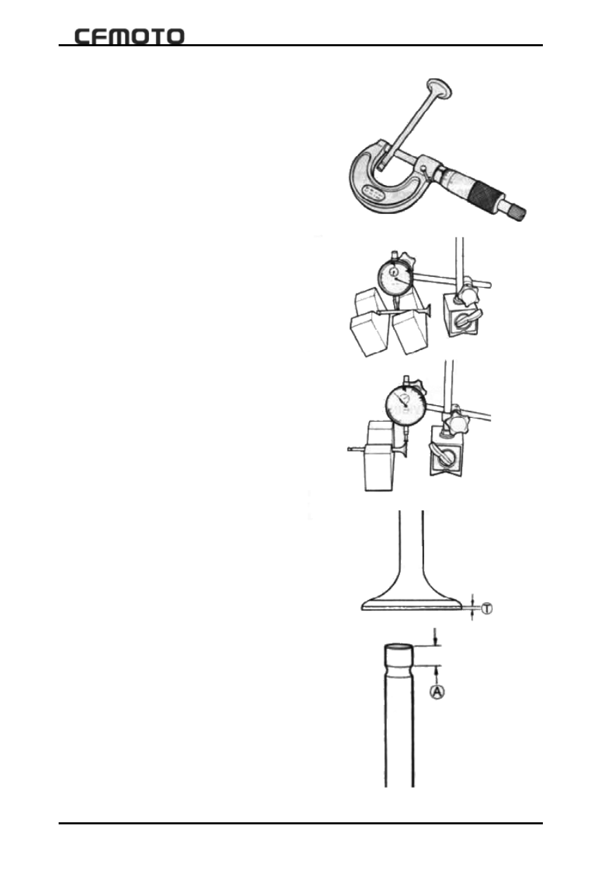
Valve stem jump
z
As illustrated,use a V-shape to support valve,
use a micrometer to measure the jump.
Tool:micrometer and V-shape support
Valve head jump
z
As illustrated,use a micrometer gauge to
meausre valve head jump. If the jump is over
limit,replace valve.
Limit
:0.03
mm
.
Tool:Megnetic clock seat, micrometer gauge
(1/100)and V-shape seat.
Valve head surface wearing
z
Check wearing of every valve head surface,
replace a new valve in case of wearing or
damage.Measure valve head width T, if valve
head depth
is smaller than limit,replace
valve.
Valve head limit
:0.5
mm
Tool:Feeler gauge
External diameter of valve stem
z
Measure with a micrometergauge
Valve intake
4.975-4.990
mm
Valve exhaust
4.955-4.970
mm
Tool:Micrometer gauge
(0-25
mm
)
Valve step end status
z
Check valve step end surface for corrosion
and wearing. If A is less than the limit,repair
it.
Valve stem length limit
:4.5
mm
Tool:feeler gauge;