CFMoto motorcycle CF150-A. Service Manual - part 5


  Index      Manuals     CFMoto motorcycle CF150-A. Service Manual


Search            copyright infringement  


Content      ..     3      4      5      6     ..


CFMoto motorcycle CF150-A. Service Manual - part 5


4-10


Stationary Seal Ring:

z

Carefully check stationary seal for damage, espe-

cially the seal face.

z

IN case of damage or leakage,replace the station-

ary seal ring,if necessary ,replace moving seal ring.


Moving seal Ring

:

z

Carefully check Moving seal for damage, especially

the seal face

;


Water Pump Body

:

z

Check the joint surface of water pump body with

bearing and seal ,if damage, replace it .


Water Pump Impeller:

z

Check impeller and shaft,if damage,replace with new

impeller.

z

Check O-ring carfully,if it’s damaged,replace it with

a new one.


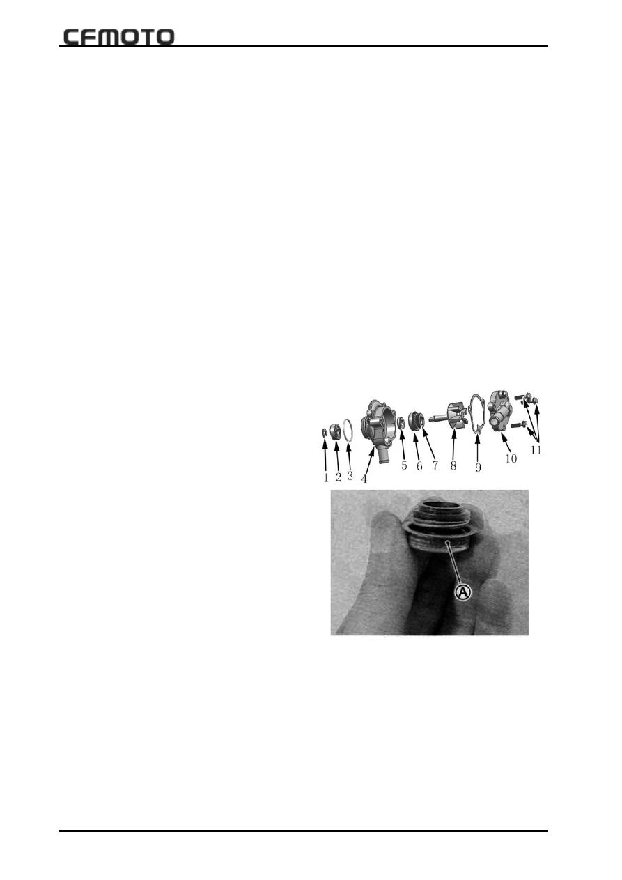
Assembly and installation of water   pump

z

Install Oil seal 5into water pump 4 with special

tool.

z

Install Stationary Seal  6 into water pump 4 with

special tool.

Note

:

 Apply sealant to side “A ” of stationary seal.

z

Install bearing  2 into water pump 4.

z

Install moving seal 7  on the impeller 8.

Note

:

side  “A”Moving seal  is outward.

z

Apply grease to impeller shaft

z

Install impeller shaft which installed Stationary

Seal to water pump body

z

Install new ring to water pump shaft

 1

z

Install new gasket 9 to water pump body

z

Install water pump cover 10 and tighten the bolts

11 and bleed bolt

z

check impeller for smooth turning

z

Install new O-ring

Note

:

Apply engine Oil to the O-ring when install

water Pump.

z

Install water pump and joint waterhoses

-------------------------------------------------------------------------------------------------------------------------------------------------------------

4-11


4  Cooling and Lubricating System

 4

4

4

4

4


Lubricant system drawing

157MJ-2A ENGINE LUBRICANT SYSTEM

DRAWING

-------------------------------------------------------------------------------------------------------------------------------------------------------------

4-12


z

Schematic diagram of engine lubrication system


 1

.

crankcase oil tray     2

.

engine oil screen    3

.

Oil Strainer Cover

      4

.

Oil Level Mirror         5

.

Oil drain plug        6

.

Oil Pump Assy

      7

.

Oil Fiter Assy.          8

.

Clutch      9

.

Countershaft      10

.

Mainshaft     11

.

Crankshaft

     12

.

Cylinder Assy.     13

.

Piston     14

.

Camshaft


z

Engine lubrication system:most of parts inside engine which run at high speed,like

 piston,   Crankshaft,Camshaft all need great lubrication,the good lubrication is the base of

the good condition of engine working.


157MJ-2A engine is used pressure and splash lubrication system,Apply special engine oil for

 4-Stroke engine,Engine Oil is not only used for lubrication,but also for clean  rustproof,sealing

and cooling.

Inspection of Lubrication system

          (see page3-12)

Inspection of engine oil pump

          (see page 5-3)

-------------------------------------------------------------------------------------------------------------------------------------------------------------

5-1

                             5 ENGINE REMOVAL AND ASSEMBLY

 5

5

5

5

5

    Engine removal, inspection and assembly


Page location 

Location PARTS 

REMOVAL INSPECTION ASSEMBLY 

REMARK 

Engine 
outside 

CARBURETOR 5-2 

— 

5-38 


WATER PUMP 

5-2 

— 

5-37 


ENGINE  

LEFT 

LEFT SIDE COVER 

5-2 

— 

5-38 


MAIN  CHAIN 

5-2 

— 

5-38 


GEAR TOUCHER 

5-2 

— 

5-38 


DUAL GEAR CHAIN 

5-2 

— 

5-38 


ENGINE 


STARTOR MOTOR 

5-3 

— 

5-37 


OIL FILTER COVER AND 
PAPER ELEMENT 

5-3 — 5-34 


RIGHT SIDE COVER 

5-3 

— 

5-33 


OIL PUMP SECONDARY 
GEAR 

5-3 — 5-32 


OIL PUMP MAIN GEAR 

5-3 

— 

5-32 


CLUTCH 5-3 

5-23 

5-32 


OIL PUMP 

5-3 

— 

5-32 


ENGINE  

HEAD 

TIMING SPROCKET 
TENSIONER 

5-4 — 5-37 


SPARK PLUG 

5-4 

— 

5-17 


CYLINDER HEAD&COVER 

5-4 

5-10 

5-36 


CAMSHAFT 5-4 

5-17 

5-36 


MAGNETO ROTOR 

5-5 

— 

5-37 


MAIN CHAIN 

5-5 

5-28 

5-37 


CYLINDER COVER 

5-6 

5-11 

5-35 


CYLINDER BODY 

5-6 

5-19 

5-35 


TIMING SPROCKET 

5-7 

— 

5-36 


PISTON 5-7 

5-20 

5-34 


CRANKSHAFT 

GEARSHIFT ROD 

5-7 

5-27 

5-31 


CAMSHAFT CHAIN 

5-7 

— 

5-31 


FILTER COVER 

5-8 

— 

5-31 


RIGHT CRANKSHAFT 

5-8 

— 

5-30 


GEAR BOX,FORK,MAIN 
SHAFT 

5-8 5-25 5-29  

CRANKSHAFT 5-9 

5-22 

5-29 


REMARK:ARROW MEANS REMOVAL PROCEDURES AND 

PROCEDURE IS REVERSE FOR ASSEMBLY. 

-------------------------------------------------------------------------------------------------------------------------------------------------------------

5-2


Engine removal

Preparations

z

Prepare a plate for parts;

z

Prepare tools;

z

Drain all oil and coolant;

z

Loosen clamp 2,remove water pipe

connection, loosen 3 pieces of bolt 1, and

take out water pump.

 Water pump


Engine left side

Left side cover

Remove 10 pieces of assembly bolts on left

side cover and remove left rear cover, left front

cover and left front mat.

Main drive chain

Loosen bolt 2, and remove main drive chain;

Carburetor

z

Loosen two bolts 1, and remove

carburetor 2.


Engine outside

Gear contactor

Use a screwdriver to loosen two pieces of

bolts 3, and remove gear contactor

DUAL GEAR

Take out dual gear axle and remove duel gear

4.


-------------------------------------------------------------------------------------------------------------------------------------------------------------

5-3

                             5 ENGINE REMOVAL AND ASSEMBLY

 5

5

5

5

5

Oil filter cover and element:

Loosen 3 pieces of assembly bolts 3, and

remove filter cover 4 then element and other

parts;

Clutch

z

Loosen 5 pieces of bolt 6 and remove clutch

plate 7, then take out clutch main plate and

driven plate;

z

Loosen clutch tightening bolt 8,   remove 9

and clutch gear 10 and  then other parts;

z

Take out clutch main driven gear 11.


Engine right side

Starting motor

Loosen two pieces of bolt 1 and remove start-

ing motor 2.


 Right side cover

Loosen right side cover bolts 5 & 6, remove

right side cover 7 and right side cover mat.


Driven gear oil pump

 Use special tool to remove clamp 1 and then

remove driven gear 2;

Main gear oil pump

Use chisel to loosen bolt 4 and remove

main gear 5;


Oil pump

z

Loosen 3 pieces of bolt 12, and then remove

oil pump 13.

-------------------------------------------------------------------------------------------------------------------------------------------------------------

5-4

Camshaft


Engine head

Timing sprocket tensoioner

z

Remove bolt 1 and take out tensioner spring;

z

Remove tensioner bolt and then the

tensioner.

z

Use a special tool to remove spark plug 1.

Spark plug

 Note:Do not let dowel pin fall into

crankcase.

z

Remove valve room cover 1;

z

Remove cover bolt;

z

Remove cylinder cover;

z

Remove cylinder cover pin.

z

Remove timing sprocket bolt 1;

z

Remove camshaft spacer 3;

z

Remove timing sprocket 2 from camshaft;

z

Take out camshaft 1;

N o t e : D o   n o t   l e t   s p a c e r   f a l l   i n t o

crankcase. Hook the timing sprocket

during removal to avoid drom into

crankcase.


  Cylinder cover

-------------------------------------------------------------------------------------------------------------------------------------------------------------

5-5

                             5 ENGINE REMOVAL AND ASSEMBLY

 5

5

5

5

5

MAGNETO ROTOR

z

Remove tightening bolt 1;

z

Use tool to fix on the outer thread and re-

move the rotor and get off the woodruf key.


 Tool: Rotor puller


Main gear


z

Remove the main gear.


-------------------------------------------------------------------------------------------------------------------------------------------------------------

5-6

Cylinder tightening bolt

z

Loosen 4 pieces of  tightening bolts.

Cylinder head

z

Loosen 4 pieces of cylinder cover bolts and

copper mat.

z

Remove cylinder cover 1.

Cylinder body

z

Remove pin 1;

z

Remove gasket 2;

z

Remove timing chain guide;

z

Remove cylinder 4;

-------------------------------------------------------------------------------------------------------------------------------------------------------------

5-7

                             5 ENGINE REMOVAL AND ASSEMBLY

 5

5

5

5

5

Timing chain

z

Remove dowel pin;

z

Remove gasket 2;

z

Remove timing chain;


Piston

z

Use clipper to remove piston pin 4;

z

Remove pistion pin 5;

z

Remove piston.

Note:

Note:

Note:

Note:

Note:

z

Keep order with cylinder during  piston

assembly;

z

During piston removal, clear pin or groove

surface, and use too to remove piston if

necessary. Do not use knock out the piston

with hammer


Tool:Piston pin removal tool

Engine crankcase

Gearshift rod unit

z

Remove gearshift rod unit 1;

Gearshift camshaft driven gear

z

Use a screwdriver to loosen 4 pieces of

bolts 2;

z

Remove gearshift camshaft driver gear

Note:

During removal of driven gear 3, do not

loosen 4 and 5, spring 6 and pin 7.

-------------------------------------------------------------------------------------------------------------------------------------------------------------

5-8

Right crankcase

z

Loosen bolts on crankcase;

z

Put left crankcase downwards and right one

upward, use tool to separate left and right

crankcases, then remove right crankcase.

Filter element cover

z

Loosen bolt 1 and take out spacer pin spring

and neutral spacer pin.

z

Loosen 3 pieces of bolts 2;

z

Remove cover 3.

Gearbox,shifting fork axle and shifting

fork,main and driven axle

z

Remove shifting fork axle 1;

z

Remove shiting fork 2;

z

Remove shifting fork axle 3;

z

Remove shiting fork 4;

z

Remove main gear 6 and driven gear 5;

z

Remove gearbox.

-------------------------------------------------------------------------------------------------------------------------------------------------------------

5-9

                             5 ENGINE REMOVAL AND ASSEMBLY

 5

5

5

5

5

Crankshaft

z

Use tool to separate crankshaft from left

crankcase;

Tool: Crankshaft separating tool

-------------------------------------------------------------------------------------------------------------------------------------------------------------

5-10

 Engine parts inspection

 Cylinder head cover

Disassembly

Warning:during 

disassembly, make sure

each part position so assembly can be made

just same as done in factory.

z

Remove 2 valve covers;

z

Disassemble spacer 2;

z

Disassemble two rocker arms 2;

z

Disassemble two rocker arms 4.

Cylinder cover surface

Clean glue on cylinder cover and put it plain,

use a feeler gauge to check surface situation.

Limit:0.05mm

Tool: feeler gauge.


Replace with new parts if limit is exceeded.

Rocker arm

z

Use a micrometer to measure external

diameter.

External diameter:Rocker arm(air inlet and

outlet)

Standard

: 11.977~11.995mm

Tool: Micrometer

(0~ 25mm)

Note:Cylinder head and cover are an

assy,and should be replaced as a set.


Touching surface of cylinder cover

-------------------------------------------------------------------------------------------------------------------------------------------------------------

5-11

                             5 ENGINE REMOVAL AND ASSEMBLY

 5

5

5

5

5


Rocker arm

z

During valve rocker arm, check also surface

1 and adjustment bolt for wearing ;

z

Valve rocker arm inner diameter:standard

:

12.000¡«12.018mm

Tool:Innter diameter gauge


Assembly

z

Coat rocker inner hole and rocker arm with

oil and assemble rocker arm as illustrated.

z

Install rocker arm O-ring, make sure rocker

arm surface in line with spacer position A.

Note:

Note:

Note:

Note:

Note:

Replace O-ring for every rocker arm inspec-

tion

Cylinder cover

Disassembly

z

Remove air inlet pipe.

z

Remove thermostat cover 1, water

temperature  sensor 2 and chain tensioner 3.

-------------------------------------------------------------------------------------------------------------------------------------------------------------

5-12

z

Take out thermostat;

z

Use a special tool to compress valve spring

and then remove clamp 1.

z

Take out valve spring upper seat 2 and then

outer spring 3 and inner spring  

4.

Tool: Valve compress tool.

z

Remove outlet valve 5 and inlet 6

;

z

Take out sealing 7.

z

Remove seat valve spring.

-------------------------------------------------------------------------------------------------------------------------------------------------------------

5-13

                             5 ENGINE REMOVAL AND ASSEMBLY

 5

5

5

5

5

Cylinder deformation

z

Clear burning room and touching surface.

z

Use gauge to measure cylinder head and

touching deformation.Replace  cylinder head

cover if necessary.

Cylinder head deforming limit

:0.03mm

Tool: Feel gauge, kinfe feeler

;

V a l v e   s t e p   a n d   g u i d e   b u s h i n g

composition.

z

Raise valve seat 10 mm higher from valve,

and use micrometer gauge to measure the

deviation at  X and Y vertical position.Replace

valve or cylinder if limit is exceeded.

Deviation limit

(

Valve intake and exhaust

)£º

0.25

mm

Tools:Micrometer gauge and magnetic clock

seat.

Valve width

:

:

:

:

:

z

Coat a  layer of color on A and then insert

valve and turn gently,in order to get clear trace

use tool to fix valve head.

z

Coating trace on valve head must be con-

tinuous and strip width must be within follow

limit. Repair if nenessary.

Standard valve seat width

.:0.9-1.1

mm

Tool:Valve repair.

-------------------------------------------------------------------------------------------------------------------------------------------------------------


Content      ..     3      4      5      6     ..