SINUMERIK 840D sl/828D. Job Planning. Programming Manual (2010-2018) - page 24
Additional functions
14.4 Wait for valid axis position (WAITENC)
Program code
Comment
IF $P_PROG_EVENT == 4
; Power-up
IF $P_TRAFO <> 0
; Transformation has been selected.
WAITENC
; Wait for valid axis positions of the orientation axes.
TOROTZ
; Rotate the Z axis of the WCS towards the tool axis.
ENDIF
M17
ENDIF
The tool can then be retracted in JOG mode by means of a retraction movement towards the
tool axis.
Job Planning
682
Programming Manual, 03/2010, 6FC5398-2BP20-1BA0
Additional functions
14.5 Check scope of NC language present (STRINGIS)
14.5
Check scope of NC language present (STRINGIS)
Function
Using the function STRINGIS(...) it can be checked as to whether the specified string is
available as element of the NC programming language in the actual language scope.
Definition
INT STRINGIS(STRING <Name>)
Syntax
STRINGIS(<Name>)
Meaning
STRINGIS:
Function with return value
<name>:
Name of the NC programming language element to be checked
Return value:
The return value format is yxx (decimal).
Elements of the NC programming language
The following elements of the NC programming language can be checked:
● G codes of all existing G function groups e.g. G0, INVCW, POLY, ROT, KONT, SOFT, CUT2D, CDON,
RMB, SPATH
● DIN or NC addresses such as e.g. ADIS, RNDM, SPN, SR, MEAS
● Functions e.g. TANG(...) or GETMDACT
● Procedures, e.g. SBLOF.
● Keywords e.g. ACN, DEFINE or SETMS
● System data, e.g. machine data $M... , setting data $S... or option data $O...
● System variable $A... , $V... , $P...
● Arithmetic parameter R...
● Cycle names of activated cycles
● GUD and LUD variables
● Macro names
● Label names
Job Planning
Programming Manual, 03/2010, 6FC5398-2BP20-1BA0
683

Additional functions
14.5 Check scope of NC language present (STRINGIS)
Return value
Only the first 3 decimal positions of the return value are relevant. The return value format is
yxx, with y = basis information and xx = detailed information.
Return value
Meaning
000
The 'name' string is not known in this system 1)
100
The 'name' string is an element of the NC programming language, but currently cannot be programmed
(option / function is inactive)
2xx
The 'name' string is a programmable element of the NC programming language (option/function is
active). The detailed information xx contains additional information about the element type:
xx
Meaning
01
DIN address or NC address2)
02
G code (e.g. G04, INVCW)
03
Function with return value
04
Function without return value
05
Keyword (e.g. DEFINE)
06
Machine ($M...), setting ($S...) or option data ($O...)
07
System parameters, e.g.. system variable ($...) or arithmetic parameter (R...)
08
Cycle (the cycle must be loaded into the NCK and the cycle program must be active 3) )
09
GUD variable (the GUD variable must be defined in the GUD definition files and the GUD
variables activated)
10
Macro name (the macro must be defined in the macro definition files and macros activated) 4)
11
LUD variable of the actual part program
12
ISO G code (ISO language mode must be active)
400
The 'name' string is an NC address, that was not identified as xx == 01 or xx == 10 and is not G or R 2)
y00
No specific assignment possible
1) Depending on the control, under certain circumstances, only a subset of the Siemens NC language commands are
known, e.g. SINUMERIK 802D sl. For these controls, for strings that are principally Siemens NC language commands, a
value of 0 is returned. This behavior can be changed using MD10711 $MN_NC_LANGUAGE_CONFIGURATION. For
MD10711 = 1, then a value of 100 is always returned for Siemens NC language commands.
2) NC addresses are the following letters: A, B, C, E, I, J, K, Q, U, V, W, X, Y, Z. These NC addresses can also be
programmed with an address extension. The address extension can be specified when checking with STRINGIS.
Example: 201 == STRINGIS("A1").
The letters: D, F, H, L, M, N, O, P, S, T are NC addresses or auxiliary functions that are defined by the user. A value of 400
is always returned for these. Example: 400 == STRINGIS( "D" ). These NC addresses cannot be specified with address
extension when checking with STRINGIS.
Example: 000 == STRINGIS("M02"), but 400 == STRINGIS("M").
3) Names of cycle parameters cannot be checked with STRINGIS.
4) Address, defined as macro, e.g. G, H, M, L are identified as macro
Job Planning
684
Programming Manual, 03/2010, 6FC5398-2BP20-1BA0
Additional functions
14.5 Check scope of NC language present (STRINGIS)
Examples
In the following examples it is assumed that the NC language elements specified as string -
as long as nothing else is noted - can in principle be programmed in the control.
1. String "T" is defined as auxiliary function:
400 == STRINGIS("T")
000 == STRINGIS ("T3")
2. String "X" is defined as axis:
201 == STRINGIS("X")
201 == STRINGIS("X1")
3. String "A2" is defined as address with extension:
201 == STRINGIS("A")
201 == STRINGIS("A2")
4. String "INVCW" is defined as named G code:
202 == STRINGIS("INVCW")
5. String "$MC_GCODE_RESET_VALUES" is defined as machine data:
206 == STRINGIS("$MC_GCODE_RESET_VALUES")
6. String "GETMDACT" is an NC language function:
203 == STRINGIS("GETMDACT ")
7. String "DEFINE" is a keyword:
205 == STRINGIS("DEFINE")
8. String "$TC_DP3" is a system parameter (tool length component):
207 == STRINGIS("$TC_DP3")
9. String "$TC_TP4" is a system parameter (tool size):
207 == STRINGIS("$TC_TP4")
10.String "$TC_MPP4" is a system parameter (magazine location state):
- Tool magazine management is active: 207 == STRINGIS("$TC_MPP4") ;
- Tool magazine management is not active: 000 == STRINGIS("$TC_MPP4")
Also refer to the paragraph below: Tool magazine management.
11.The string "MACHINERY_NAME" is defined as GUD variable:
209 == STRINGIS("MACHINERY_NAME")
12.The "LONGMACRO" string is defined as macro:
210 == STRINGIS("LONGMACRO")
13.The string "MYVAR" is defined as LUD variable:
211 == STRINGIS("MYVAR")
14.String "XYZ" is a command that is not known in the NCK, GUD variable, macro or cycle
name:
000 == STRINGIS("XYZ")
Job Planning
Programming Manual, 03/2010, 6FC5398-2BP20-1BA0
685
Additional functions
14.5 Check scope of NC language present (STRINGIS)
Tool magazine management
If the tool magazine management function is not active, STRINGIS supplies for the system
parameters of the tool magazine management, independent of the machine data
● MD10711 $MN_NC_LANGUAGE_CONFIGURATION
always a value of 000.
ISO mode
If the "ISO mode" function is active:
● MD18800 $MN_MM_EXTERN_LANGUAGE (activation, external NC languages)
● MD10880 $MN_ MM_EXTERN_CNC_SYSTEM (control system to be adapted)
STRINGIS checks the specified string initially as SINUMERIK G-Code. If the string is not a
SINUMERIK G code, then it is subsequently checked as ISO G code.
Programmed switchovers (G290 (SINUMERIK mode), G291 (ISO Mode)) have no effect on
STRINGIS.
Example
The machine data, relevant for the function STRINGIS(...), have the following values:
● MD10711 $MN_NC_LANGUAGE_CONFIGURATION = 2 (only the NC language
commands whose options are set are considered to be known)
● MD19410 $ON_TRAFO_TYPE_MASK = 'H0' (option: transformations)
● MD10700 $MN_PREPROCESSING_LEVEL='H43' (preprocessing for cycles is active)
The following program example is executed without error message:
Program code
Comment
N1 R1=STRINGIS("TRACYL")
;
R1 == 0, as TRACYL is identified as
;
"not known" because of the missing transformation
;
option
N2 IF STRINGIS("TRACYL") == 204
;
N3 TRACYL(1,2,3)
;
N3 is skipped
N4 ELSE
N5 G00
;
and instead, N5 is executed
N6 ENDIF
N7 M30
Job Planning
686
Programming Manual, 03/2010, 6FC5398-2BP20-1BA0
Additional functions
14.6 Function call ISVAR and read machine data array index
14.6
Function call ISVAR and read machine data array index
Function
The ISVAR command is a function as defined in the NC language that has a
● Function value of type BOOL
● transfer parameter of type STRING
The ISVAR command returns TRUE if the transfer parameter contains a variable known in
the NC (machine data, setting data, system variable, general variables such as GUDs).
Syntax
ISVAR(<variable identifier>)
ISVAR(<identifier>,[<value>,<value>])
Significance
<Variable identifier>
Transfer parameter of type string can be undimensioned,
1-dimensional, or 2-dimensional.
<identifier>
Identifier with a known variable with or without an array
index as machine data, setting data, system variable, or
general variable.
Extension:
For general and channel-specific machine data, the first
element of the array will be read even when no index is
specified.
<value>
Function value of type BOOL
Checks
The following checks are made in accordance with the transfer parameter:
● Does the identifier exist
● Is it a 1- or 2-dimensional array
● Is an array index permitted
Only if all these checks have a positive result will TRUE be returned. If a check has a
negative result or if a syntax error has occurred, it will return FALSE. Axial variables are
accepted as an index for the axis names but not checked.
Extension: Read machine data and setting data array without index.
If there is no index for general and channel-specific machine data, alarm 12400 "channel %
1 block % 2 array % 3 element not present" is no longer output.
Job Planning
Programming Manual, 03/2010, 6FC5398-2BP20-1BA0
687
Additional functions
14.6 Function call ISVAR and read machine data array index
At least the axis index must still be programmed for axis-specific machine data. Otherwise
alarm 12400 will be issued.
Example: Function call ISVAR
Program code
Comments
DEF INT VAR1
DEF BOOL IS_VAR=FALSE
; Transfer parameter is a general variable
N10 IS_VAR=ISVAR("VAR1")
; IS_VAR is in this case, TRUE
DEF REAL VARARRAY[10,10]
DEF BOOL IS_VAR=FALSE
; Various syntax versions
N20 IS_VAR=ISVAR("VARARRAY[,]")
; IS_VAR is TRUE with a
two-dimensional array
N30 IS_VAR=ISVAR("VARARRAY")
; IS_VAR is TRUE, variable exists
N40 IS_VAR=ISVAR("VARARRAY[8,11]")
; IS_VAR is FALSE, array index is not
permitted
N50 IS_VAR=ISVAR("VARARRAY[8,8")
; IS_VAR is FALSE, syntax error for
missing "]"
N60 IS_VAR=ISVAR("VARARRAY[,8]")
; IS_VAR is TRUE, array index is permitted
N70 IS_VAR=ISVAR("VARARRAY[8,]")
; IS_VAR is TRUE
DEF BOOL IS_VAR=FALSE
; Transfer parameter is a machine data
N100 IS_VAR=ISVAR("$MC_GCODE_RESET_VALUES[1]"
; IS_VAR is TRUE
DEF BOOL IS_VAR=FALSE
; Transfer parameter is a system variable
N10 IS_VAR=ISVAR("$P_EP")
; IS_VAR is in this case TRUE
N10 IS_VAR=ISVAR("$P_EP[X]")
; IS_VAR is in this case TRUE
Example: Read machine data array with and without index.
The first element will be read for
R1=$MC_EXTERN_GCODE_RESET_VALUES
as previous, this corresponds to
R1=$MC_EXTERN_GCODE_RESET_VALUES[0]
or the first element will be read
R1=$MA_POSTCTRL_GAIN[X1]
The corresponds to as before
R1=$MA_POSTCTRL_GAIN[0, X1]
The first element in synchronized actions is also read for
WHEN TRUE DO $R1 = $MC_EXTERN_GCODE_RESET_VALUES
The corresponds to as before
WHEN TRUE DO $R1 = $MC_EXTERN_GCODE_RESET_VALUES[0]
and would previously not be read with alarm 12400.
The alarm 12400 will still be issued for
R1=$MA_POSTCTRL_GAIN
Job Planning
688
Programming Manual, 03/2010, 6FC5398-2BP20-1BA0
Additional functions
14.7 Learn compensation characteristics (QECLRNON, QECLRNOF)
14.7
Learn compensation characteristics (QECLRNON, QECLRNOF)
Function
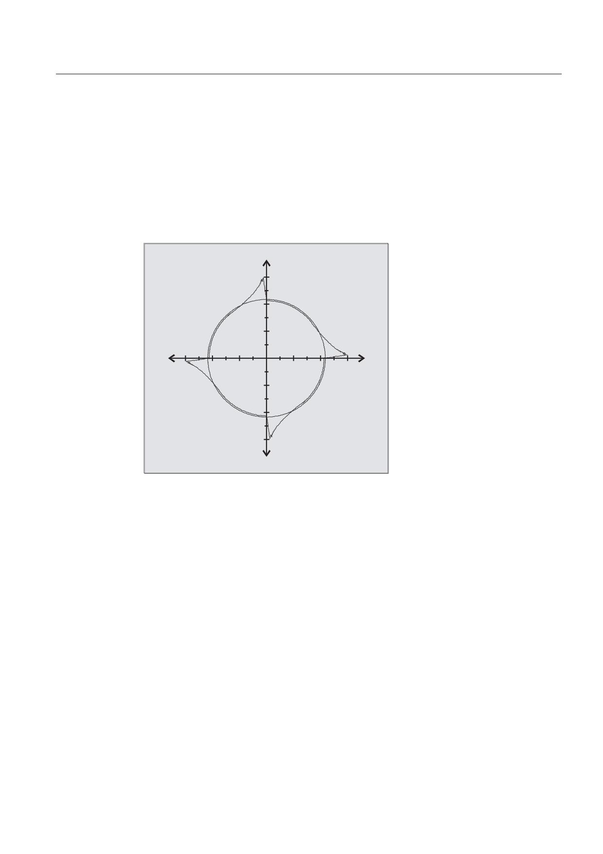
Quadrant error compensation (QEC) reduces contour errors that occur on reversal of the
traversing direction due to mechanical non-linearities (e.g. friction, backlash) or torsion. On
the basis of a neural network, the optimum compensation data can be adapted by the control
during a learning phase in order to determine the compensation characteristics
automatically. Learning can take place simultaneously for up to four axes.
[
P
,,
,
[
P
,,,
,9
Syntax
QECLRNON
QECLRNOF
Activate learning operation: QECLRNON
The actual learning operation is activated in the NC program using the command QECLRNON
specifying the axes:
QECLRNON (X1, Y1, Z1, Q)
The characteristics are only changed if the command is active.
Deactivating learning: QECLRNOF
After the learning motions of the required axes have been completed, the learning process is
simultaneously deactivated for all axes using QECLRNOF.
Job Planning
Programming Manual, 03/2010, 6FC5398-2BP20-1BA0
689
Additional functions
14.7 Learn compensation characteristics (QECLRNON, QECLRNOF)
Significance
QECLRNON (axis 1,…4)
Activate "Learn quadrant error compensation" function
QECLRNO
Deactivate "Learn quadrant error compensation" function
QECLRN.SPF
Learning cycle
QECDAT.MPF
Sample NC program for assigning system variables and for
parameterizing the learning cycle
QECTEST.MPF
Sample NC program for the circularity test
Description
The traversing movements of the axes required for the learning process are generated with
the aid of an NC program. The learning movements are stored in the program in the form of
a learning cycle.
First teach-in
Sample NC programs contained on the disk of the standard PLC program are used to teach
the movements and assign the QEC system variables in the initial learning phase during
startup of the control:
Relearning
The learnt characteristics can be optimized with subsequent learning. The data stored in the
user memory are used as the basis for optimization. Optimization is performed by adapting
the sample NC programs to your needs.
The parameters for the learning cycle (e.g. QECLRN.SPF) might have to be changed for
"relearning".
● Set "Learn mode" = 1
● Reduce "Number of learn passes" if required
● Activate "Modular learning" if required and define area limits.
Job Planning
690
Programming Manual, 03/2010, 6FC5398-2BP20-1BA0
Additional functions
14.8 Interactively call the window from the part program (MMC)
14.8
Interactively call the window from the part program (MMC)
Function
You can use the MMC command to display user-defined dialog windows (dialog displays) on
the HMI from the part program.
The dialog window appearance is defined in a pure text configuration (COM file in cycles
directory), while the HMI system software remains unchanged.
User-defined dialog windows cannot be called simultaneously in different channels.
Syntax
MMC(CYCLES,PICTURE_ON,T_SK.COM,BILD,MGUD.DEF,BILD_3.AWB,TEST_1,A1","
S")
Significance
MMC
Calling the dialog window interactively from the part program on the
HMI.
CYCLES
Operating area in which the configured user dialog boxes are
implemented.
PICTURE_ON
or
Command: Display selection or display deselection.
PICTURE_OFF
T_SK.COM
Com file: Name of the dialog display file (user cycles). The dialog
display design is defined here. The dialog screen is used to display
user variables and/or comment texts.
DISPLAY
Name of dialog display: The individual displays are selected via the
names of the dialog displays.
MGUD.DEF
User data definition file, which is addressed while reading/writing
variables.
PICTURE_3.AWB
Graphics file
TEST_1
Display time or acknowledgement variable.
A1
Text variables...",
"S"
Acknowledgement mode: synchronous, acknowledgement via "OK"
soft key.
References
Refer to the Commissioning Manual for detailed information on programming the MMC
command (incl. programming examples).
Job Planning
Programming Manual, 03/2010, 6FC5398-2BP20-1BA0
691

Additional functions
14.9 Program runtime/part counter
14.9
Program runtime/part counter
14.9.1
Program runtime/part counter (overview)
Information on the program runtime and workpiece counter are provided to support the
machine tool operator.
This information can be processed as system variables in the NC and/or PLC program. This
information is also available to be displayed on the operator interface.
14.9.2
Program runtime
Function
The "program runtime" function provides internal NC timers to monitor technological
processes, which can be read into the part program and into synchronized actions via the
NC and channel-specific system variables.
The trigger for the runtime measurement ($AC_PROG_NET_TIME_TRIGGER) is the only
system variable of the function that can be written to and is used to selectively measure
program sections. This means that by writing the trigger into the NC program, the time
measurement can be activated and deactivated.
System variable
Meaning
Activity
NC-specific
$AN_SETUP_TIME
Time since the last control power up with default
• Always active
values ("cold restart") in minutes.
Is automatically reset to "0" every time the control
powers up with default values.
$AN_POWERON_TIME
Time since the last normal control power up ("warm
restart") in minutes.
Is automatically reset to "0" every time the control
powers up normally.
Job Planning
692
Programming Manual, 03/2010, 6FC5398-2BP20-1BA0

Additional functions
14.9 Program runtime/part counter
System variable
Meaning
Activity
Channel-specific
$AC_OPERATING_TIME
Total runtime of NC programs in automatic mode in
• Activated via
seconds.
MD27860
The value is automatically reset to "0" every time the
• Only AUTOMATIC
mode
control powers up.
$AC_CYCLE_TIME
Runtime of the selected NC program in seconds.
The value is automatically reset to "0" every time a
new NC program starts up.
$AC_CUTTING_TIME
Processing time in seconds
The runtime of the path axes (at least one is active) is
measured in all NC programs between NC start and
end of program/NC reset without rapid traverse
active. The measurement is interrupted when a dwell
time is active.
The value is automatically reset to "0" every time the
control powers up with default values.
$AC_ACT_PROG_NET_TIME
Actual net runtime of the current NC program in
• Always active
seconds.
• Only AUTOMATIC
Is automatically reset to "0" when a new NC program
mode
starts.
$AC_OLD_PROG_NET_TIME
Net runtime in seconds of the program that has just
be correctly ended with M30
$AC_OLD_PROG_NET_TIME_COUNT
Changes to $AC_OLD_PROG_NET_TIME
After POWER ON,
$AC_OLD_PROG_NET_TIME_COUNT is at "0".
$AC_OLD_PROG_NET_TIME_COUNT is always
increased if the control has newly written to
$AC_OLD_PROG_NET_TIME.
Job Planning
Programming Manual, 03/2010, 6FC5398-2BP20-1BA0
693

Additional functions
14.9 Program runtime/part counter
System variable
Meaning
Activity
$AC_PROG_NET_TIME_TRIGGER
Trigger for the runtime measurement:
• Only AUTOMATIC
mode
0
Neutral state
The trigger is not active.
1
Exit
Ends the measurement and copies the value
from $AC_ACT_PROG_NET_TIME into
$AC_OLD_PROG_NET_TIME.
$AC_ACT_PROG_NET_TIME is set to "0" and
then continues to run.
2
Start
Starts the measurement and in so doing sets
$AC_ACT_PROG_NET_TIME to "0".
$AC_OLD_PROG_NET_TIME is not changed.
3
Stop
Stops the measurement. Does not change
$AC_OLD_PROG_NET_TIME and keeps
$AC_ACT_PROG_NET_TIME constant until it
resumes
4
Resume
The measurement is resumed, i.e. a
measurement that was previously stopped is
continued. $AC_ACT_PROG_NET_TIME
continues to run. $AC_OLD_PROG_NET_TIME
is not changed.
All system variables are reset to 0 as a result of POWER ON!
Reference:
A detailed description of the listed system variables is provided in:
Function Manual, Basic Functions; Mode Group, Channel, Program Operation, Reset Response (K1), Chapter: Program
runtime
Note
Machine manufacturer
Machine data MD27860 $MC_PROCESSTIMER_MODE is used to switch-in the timer that
can be activated.
The behavior of active time measurements for certain functions (e.g. GOTOS,
override = 0%, active test run feed, program test, ASUB, PROG_EVENT, …) is configured
using machine data MD27850 $MC_PROG_NET_TIMER_MODE and
MD27860 $MC_PROCESSTIMER_MODE.
References:
Function Manual, Basic Functions; BAG, Channel, Program Operation, Reset Response
(K1), Chapter: Program runtime
Job Planning
694
Programming Manual, 03/2010, 6FC5398-2BP20-1BA0
Additional functions
14.9 Program runtime/part counter
Note
Residual time for a workpiece
If the same workpieces are produced one after the other, then the timer values:
• Processing time for the last workpiece produced (see $AC_OLD_PROG_NET_TIME)
and
• Current processing time (see $AC_ACT_PROG_NET_TIME)
can be used to determine the remaining residual time for a workpiece.
The residual time is displayed on the operator interface in addition to the current processing
time.
NOTICE
Using STOPRE
The system variables $AC_OLD_PROG_NET_TIME and
$AC_OLD_PROG_NET_TIME_COUNT do not generate any implicit preprocessing stop.
This is uncritical when used in the part program if the value of the system variables comes
from the previous program run. However, if the trigger for the runtime measurement
($AC_PROG_NET_TIME_TRIGGER) is written very frequently and as a result
$AC_OLD_PROG_NET_TIME changes very frequently, then an explicit STOPRE should be
used in the part program.
General conditions
● Block search
No program runtimes are determined through block searches.
● REPOS
The duration of a REPOS process is added to the current processing time
($AC_ACT_PROG_NET_TIME).
Job Planning
Programming Manual, 03/2010, 6FC5398-2BP20-1BA0
695
Additional functions
14.9 Program runtime/part counter
Examples
Example 1: Measuring the duration of "mySubProgrammA"
Program code
N50 DO $AC_PROG_NET_TIME_TRIGGER=2
N60 FOR ii= 0 TO 300
N70 mySubProgrammA
N80 DO $AC_PROG_NET_TIME_TRIGGER=1
N95 ENDFOR
N97 mySubProgrammB
N98 M30
After the program has processed line N80, the net runtime of "mySubProgrammA" is located
in $AC_OLD_PROG_NET_TIME.
The value from $AC_OLD_PROG_NET_TIME:
● is kept beyond M30.
● is updated each time the loop is run through.
Example 2: Measuring the duration of "mySubProgrammA" and "mySubProgrammC"
Program code
N10 DO $AC_PROG_NET_TIME_TRIGGER=2
N20 mySubProgrammA
N30 DO $AC_PROG_NET_TIME_TRIGGER=3
N40 mySubProgrammB
N50 DO $AC_PROG_NET_TIME_TRIGGER=4
N60 mySubProgrammC
N70 DO $AC_PROG_NET_TIME_TRIGGER=1
N80 mySubProgrammD
N90 M30
Job Planning
696
Programming Manual, 03/2010, 6FC5398-2BP20-1BA0
Additional functions
14.9 Program runtime/part counter
14.9.3
Workpiece counter
Function
The "Workpiece counter" function makes available various counters which can be used in
particular internally in the control to count workpieces.
The counters exist as channel-specific system variables with read and write access in a
range of values from 0 to 999,999,999.
System variable
Significance
$AC_REQUIRED_PARTS
Number of workpieces to be produced (setpoint number of
workpieces)
In this counter the number of workpieces at which the actual workpiece
count ($AC_ACTUAL_PARTS) will be reset to "0" can be defined.
$AC_TOTAL_PARTS
Total number of completed workpieces (actual workpiece total)
This counter specifies the total number of all workpieces produced
since the start time. The value is only automatically reset to "0" when
the control powers up with default values.
$AC_ACTUAL_PARTS
Number of completed workpieces (actual workpiece total)
This counter registers the total number of all workpieces produced
since the start time. On condition that $AC_REQUIRED_PARTS > 0,
the counter is automatically reset to "0" when the required number of
workpieces ($AC_REQUIRED_PARTS) is reached.
$AC_SPECIAL_PARTS
Number of workpieces selected by the user
This counter supports user-specific workpiece counts. An alarm can be
defined to be output when the setpoint number of workpieces is
reached ($AC_REQUIRED_PARTS). Users must reset the counter
themselves.
Note
All workpiece counters are set to "0" when the control powers up with default values and can
be read and written independent of their activation.
Note
Channel-specific machine data can be used to control counter activation, counter reset
timing and the counting algorithm.
Note
Workpiece counting with user-defined M command
Machine data can be set so that the count pulses for the various workpiece counters are
triggered using user-defined M commands rather than the end of the program (M2/M30).
Job Planning
Programming Manual, 03/2010, 6FC5398-2BP20-1BA0
697
Additional functions
14.9 Program runtime/part counter
References
For further information about the "Workpiece counter" function see:
● Function Manual, Basic Functions; BAG, Channel, Program Operation, Reset Response
(K1), Chapter: Workpiece counter
Job Planning
698
Programming Manual, 03/2010, 6FC5398-2BP20-1BA0
Additional functions
14.10 Alarms (SETAL)
14.10
Alarms (SETAL)
Function
Alarms can be set in an NC program. Alarms are displayed in a separate field at the operator
interface. An alarm always goes hand in hand with a response from the controller according
to the alarm category.
References:
Further information on alarm responses, refer to the Commissioning Manual.
Syntax
SETAL(<alarm number>)
SETAL(<alarm number>,<character string>)
Significance
SETAL
Keyword to program an alarm.
SETAL must be programmed in a separate NC block.
<Alarm number>
Type INT variable. Contains the alarm number.
The valid range for alarm numbers lies between 60000 and 69999,
of which 60000 to 64999 are reserved for SIEMENS cycles and
65000 to 69999 are available to users.
<character string> When programming user cycle alarms, in addition, a character string
with up to 4 parameters can be specified.
Variable user texts can be defined in these parameters.
However, the following predefined parameters are available:
Parameter
Significance
%1
Channel number
%2
Block number, label
%3
Text index for cycle alarms
%4
Additional alarm parameters
Note
Alarm texts must be configured in the operator interface.
Job Planning
Programming Manual, 03/2010, 6FC5398-2BP20-1BA0
699
Additional functions
14.10 Alarms (SETAL)
Example
Program code
Comments
N100 SETAL (65000)
; Setting alarm No. 65000
Job Planning
700
Programming Manual, 03/2010, 6FC5398-2BP20-1BA0
User stock removal programs
15
15.1
Supporting functions for stock removal
Functions
Preprogrammed stock removal programs are provided for stock removal. Beyond this, you
have the possibility of generating your own stock removal programs using the following listed
functions:
● Generate contour table (CONTPRON)
● Generate coded contour table (CONTDCON)
● Deactivate contour preparation (EXECUTE)
● Determine point of intersection between two contour elements (INTERSEC)
(Only for tables that were generated using CONTPRON)
● Executing contour elements of a table block-by-block (EXECTAB)
(Only for tables that were generated using CONTPRON)
● Calculate circle data (CALCDAT)
Note
You can use these functions universally, not just for stock removal.
Prerequisites
The following must be done before calling the CONTPRON or CONTDCON functions:
● A starting point that permits collision-free machining must approached.
● The cutting radius compensation must be deactivated with G40.
Job Planning
Programming Manual, 03/2010, 6FC5398-2BP20-1BA0
701
User stock removal programs
15.2 Generate contour table (CONTPRON)
15.2
Generate contour table (CONTPRON)
Function
Contour preparation is activated using the command CONTPRON. The NC blocks that are
subsequently called are not executed, but are split-up into individual movements and stored
in the contour table. Each contour element corresponds to one row in the two-dimensional
array of the contour table. The number of relief cuts is returned.
Syntax
Activate contour preparation:
CONTPRON(<contour table>,<machining type>,<relief cuts>,
<machining direction>)
Deactivate contour preparation and return to the normal execution mode:
EXECUTE(<ERROR>)
See "Deactivate contour preparation (EXECUTE)"
Significance
CONTPRON
Command to activate contour preparation to
generate a contour table
<contour table>
Names of contour table
<machining type>
Parameter for the machining type
Type:
CHAR
"G"
Value:
Longitudinal turning: Inside
machining
"L"
Longitudinal turning: External
machining
"N"
Face turning: Inside machining
"P"
Face turning: External machining
<relief cuts>
Result variable for the number of relief cut elements
that occur
Type:
INT
<machining direction>
Parameters for the machining direction
Type:
INT
Value:
0
Contour preparation, forwards
(default value)
1
Contour preparation in both
directions
Job Planning
702
Programming Manual, 03/2010, 6FC5398-2BP20-1BA0
User stock removal programs
15.2 Generate contour table (CONTPRON)
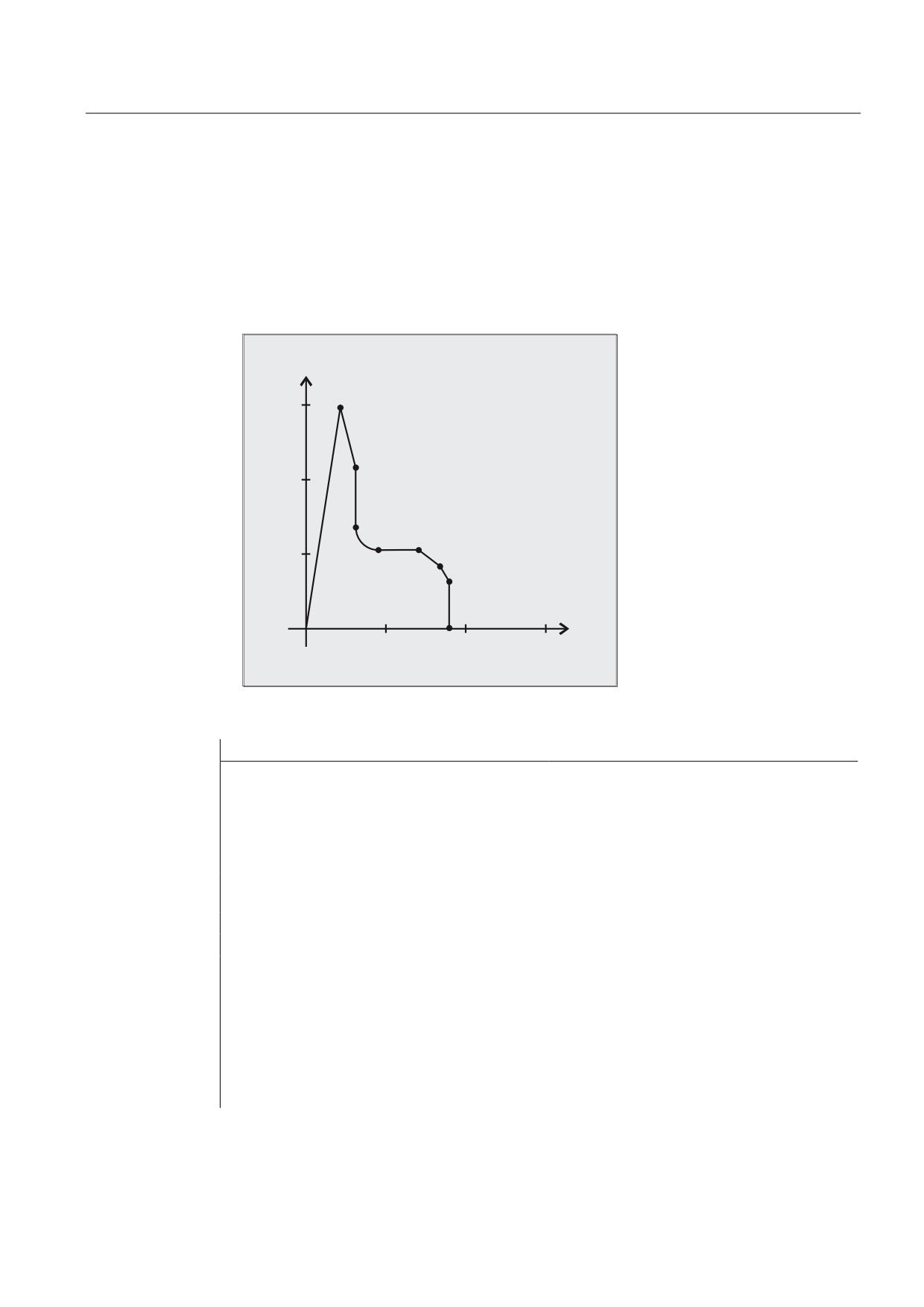
Example 1
Generating a contour table with:
● Name "KTAB"
● Max. 30 contour elements (circles, straight lines)
● One variable for the number of relief cut elements that occur
● One variable for fault messages
;
=
NC program:
Program code
Comments
N10 DEF REAL KTAB[30,11]
; Contour table with the KTAB name and
max. 30 contour elements, parameter
value 11 (number of table columns) is a
fixed quantity.
N20 DEF INT ANZHINT
; Variable for the number of relief cut
elements with the name ANZHINT.
N30 DEF INT ERROR
; Variable for fault feedback signal (0=no
fault, 1=fault).
N40 G18
N50 CONTPRON(KTAB,"G",ANZHINT)
; Activate contour preparation.
N60 G1 X150 Z20
; N60 to N120: Contour description
N70 X110 Z30
N80 X50 RND=15
N90 Z70
N100 X40 Z85
N110 X30 Z90
N120 X0
Job Planning
Programming Manual, 03/2010, 6FC5398-2BP20-1BA0
703

User stock removal programs
15.2 Generate contour table (CONTPRON)
Program code
Comments
N130 EXECUTE(ERROR)
; End filling the contour table, change
over to normal program operation.
N140 …
; Continue to process the table.
Contour table KTAB:
Index
Column
Line
(0)
(1)
(2)
(3)
(4)
(5)
(6)
(7)
(8)
(9)
(10)
7
7
11
0
0
20
150
0
82.40535663
0
0
0
2
11
20
150
30
110
-1111
104.0362435
0
0
1
3
11
30
110
30
65
0
90
0
0
2
4
13
30
65
45
50
0
180
45
65
3
5
11
45
50
70
50
0
0
0
0
4
6
11
70
50
85
40
0
146.3099325
0
0
5
7
11
85
40
90
30
0
116.5650512
0
0
6
0
11
90
30
90
0
0
90
0
0
0
0
0
0
0
0
0
0
0
0
0
0
0
0
0
0
0
0
0
0
0
0
Explanation of the column contents:
(0)
Pointer to next contour element (to the row number of that column)
(1)
Pointer to previous contour element
(2)
Coding the contour mode for motion
Possible values for X = abc
a = 102
G90 = 0
G91 = 1
b = 101
G70 = 0
G71 = 1
c = 100
G0 = 0
G1 = 1
G2 = 2
G3 = 3
(3), (4)
Starting point of contour elements
(3) = abscissa, (4) = ordinate of the current plane
(5), (6)
Starting point of the contour elements
(5) = abscissa, (6) = ordinate of the current plane
(7)
Max/min indicator: Identifies local maximum and minimum values on the
contour
(8)
Maximum value between contour element and abscissa (for longitudinal
machining) or ordinate (for face cutting). The angle depends on the type of
machining programmed.
(9), (10)
Center point coordinates of contour element, if it is a circle block.
(9) = abscissa, (10) = ordinate
Job Planning
704
Programming Manual, 03/2010, 6FC5398-2BP20-1BA0
User stock removal programs
15.2 Generate contour table (CONTPRON)
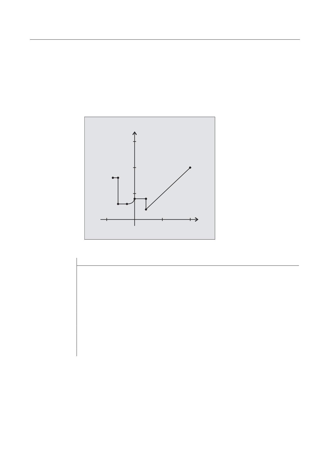
Example 2
Generating a contour table with
● Name KTAB
● Max. 92 contour elements (circles, straight lines)
● Mode: Longitudinal turning, outer machining
● Preparation, forwards and backwards
;
=
NC program:
Program code
Comments
N10 DEF REAL KTAB[92,11]
; Contour table with name KTAB and
max. 92 contour elements,
parameter value 11 is a fixed
quantity.
N20 DEF CHAR BT="L"
; Mode for CONTPRON: Longitudinal
turning, outer machining
N30 DEF INT HE=0
; Number of relief cut elements=0
N40 DEF INT MODE=1
; Preparation, forwards and
backwards
N50 DEF INT ERR=0
; Fault feedback signal
N100 G18 X100 Z100 F1000
N105 CONTPRON(KTAB,BT,HE,MODE)
; Activate contour preparation.
Job Planning
Programming Manual, 03/2010, 6FC5398-2BP20-1BA0
705
User stock removal programs
15.2 Generate contour table (CONTPRON)
Program code
Comments
N110 G1 G90 Z20 X20
N120 X45
N130 Z0
N140 G2 Z-15 X30 K=AC(-15) I=AC(45)
N150 G1 Z-30
N160 X80
N170 Z-40
N180 EXECUTE(ERR)
; End filling the contour table,
change over to normal program
operation.
Contour table KTAB:
After contour preparation is finished, the contour is available in both directions.
Index
Column
Line
(0)
(1)
(2)
(3)
(4)
(5)
(6)
(7)
(8)
(9)
(10)
0
61)
72)
11
100
100
20
20
0
45
0
0
1
03)
2
11
20
20
20
45
-3
90
0
0
2
1
3
11
20
45
0
45
0
0
0
0
3
2
4
12
0
45
-15
30
5
90
-15
45
4
3
5
11
-15
30
-30
30
0
0
0
0
5
4
7
11
-30
30
-30
45
-1111
90
0
0
6
7
04)
11
-30
80
-40
80
0
0
0
0
7
5
6
11
-30
45
-30
80
0
90
0
0
8
15)
26)
0
0
0
0
0
0
0
0
0
83
84
07)
11
20
45
20
80
0
90
0
0
84
90
83
11
20
20
20
45
-1111
90
0
0
85
08)
86
11
-40
80
-30
80
0
0
0
0
86
85
87
11
-30
80
-30
30
88
90
0
0
87
86
88
11
-30
30
-15
30
0
0
0
0
88
87
89
13
-15
30
0
45
-90
90
-15
45
89
88
90
11
0
45
20
45
0
0
0
0
90
89
84
11
20
45
20
20
84
90
0
0
91
839)
8510)
11
20
20
100
100
0
45
0
0
Job Planning
706
Programming Manual, 03/2010, 6FC5398-2BP20-1BA0
User stock removal programs
15.2 Generate contour table (CONTPRON)
Explanation of column contents and comments for lines 0, 1, 6, 8, 83, 85 and 91
The explanations of the column contents given in example 1 apply.
Always in table line 0:
1) Predecessor: Line n contains the contour end (forwards)
2) Successor: Line n is the contour table end (forwards)
Once each within the contour elements forwards:
3) Predecessor: Contour start (forwards)
4) Successor: Contour end (forwards)
Always in line contour table end (forwards) +1:
5) Predecessor: Number of relief cuts (forwards)
6) Successor: Number of relief cuts (backwards)
Once each within the contour elements backwards:
7) Successor: Contour end (backwards)
8) Predecessor: Contour start (backwards)
Always in last line of table:
9) Predecessor: Line n is the contour table start (backwards)
10) Successor: Line n contains the contour start (backwards)
Further Information
Permitted traversing commands, coordinate system
The following G commands can be used for the contour programming:
● G group 1: G0, G1, G2, G3
In addition, the following are possible:
● Rounding and chamfer
● Circle programming using CIP and CT
The spline, polynomial and thread functions result in errors.
Changes to the coordinate system by activating a frame are not permissible between
CONTPRON and EXECUTE. The same applies for a change between G70 and G71 or G700 and G710.
Replacing the geometry axes with GEOAX while preparing the contour table produces an
alarm.
Relief cut elements
The contour description for the individual relief cut elements can be performed either in a
subprogram or in individual blocks.
Stock removal independent of the programmed contour direction
The contour preparation with CONTPRON was expanded so that after it has been called, the
contour table is available independent of the programmed direction.
Job Planning
Programming Manual, 03/2010, 6FC5398-2BP20-1BA0
707
User stock removal programs
15.3 Generate coded contour table (CONTDCON)
15.3
Generate coded contour table (CONTDCON)
Function
With the contour preparation activated with CONTDCON, the following NC blocks that are called
are saved in a coded form in a 6-column contour table to optimize memory use. Each
contour element corresponds to one row in the contour table. When familiar with the coding
rules specified below, e.g., you can combine DIN code programs for cycles from the table
lines. The data of the output point are saved in the table line with the number 0.
Syntax
Activate contour preparation:
CONTDCON(<contour table>,<machining direction>)
Deactivate contour preparation and return to the normal execution mode:
EXECUTE(<ERROR>)
See "Deactivate contour preparation (EXECUTE)"
Significance
CONTDCON
Command to activate the contour preparation to
generate a coded contour table
<contour table>
Names of contour table
<machining direction>
Parameter for machining direction
Type:
INT
Value:
0
Contour preparation according to
the sequence of contour blocks
(default value)
1
Not permissible
Note
The G codes permitted for CONTDCON in the program section to be included in the table are
more comprehensive than for CONTPRON. Further, feed rates and feed rate type are saved for
each contour section.
Job Planning
708
Programming Manual, 03/2010, 6FC5398-2BP20-1BA0
User stock removal programs
15.3 Generate coded contour table (CONTDCON)
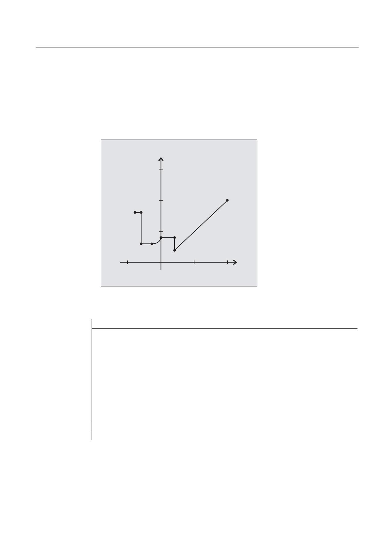
Example
Generating a contour table with:
● Name "KTAB"
● Contour elements (circles, straight lines)
● Mode: Turning
● Machining direction: Upwards
;
=
NC program:
Program code
Comments
N10 DEF REAL KTAB[9,6]
; Contour table with name KTAB and
9 table cells. These allow
8 contour sets. The parameter
value 6 (column number in table)
is a fixed size.
N20 DEF INT MODE = 0
; Variable for the machining
direction. Standard value 0:
Only in the programmed direction
of the contour.
N30 DEF INT ERROR = 0
; Variable for the fault feedback
signal.
N100 G18 G64 G90 G94 G710
N101 G1 Z100 X100 F1000
Job Planning
Programming Manual, 03/2010, 6FC5398-2BP20-1BA0
709

User stock removal programs
15.3 Generate coded contour table (CONTDCON)
Program code
Comments
N105 CONTDCON (KTAB, MODE)
; Call contour preparation (MODE
can be omitted).
N110 G1 Z20 X20 F200
; Contour description.
N120 G9 X45 F300
N130 Z0 F400
N140 G2 Z-15 X30 K=AC(-15) I=AC(45)F100
N150 G64 Z-30 F600
N160 X80 F700
N170 Z-40 F800
N180 EXECUTE(ERROR)
; End filling the contour table,
change over to normal program
operation.
Contour table KTAB:
Column index
0
1
2
3
4
5
Line index
Contour
End point
End point
Center point
Center point
Feedrate
mode
abscissa
ordinate
abscissa
ordinate
0
30
100
100
0
0
7
1
11031
20
20
0
0
200
2
111031
20
45
0
0
300
3
11031
0
45
0
0
400
4
11032
-15
30
-15
45
100
5
11031
-30
30
0
0
600
6
11031
-30
80
0
0
700
7
11031
-40
80
0
0
800
8
0
0
0
0
0
0
Explanation of the column contents:
Line 0 Coding for the starting point:
100 (units digit): G0 = 0
Column 0:
101 (tens position): G70 = 0, G71 = 1, G700 = 2, G710 = 3
Column 1:
starting point of abscissa
Column 2:
starting point of ordinate
Column 3-4:
0
Column 5:
line index of last contour piece in the table
Job Planning
710
Programming Manual, 03/2010, 6FC5398-2BP20-1BA0
User stock removal programs
15.3 Generate coded contour table (CONTDCON)
Lines 1-n: Entries for contour pieces
100 (units digit): G0 = 0, G1 = 1, G2 = 2, G3 = 3
Column 0:
101 (tens position): G70 = 0, G71 = 1, G700 = 2, G710 = 3
102 (hundreds digit): G90 = 0, G91 = 1
103 (thousands digit): G93 = 0, G94 = 1, G95 = 2, G96 = 3
104 (ten thousands digit): G60 = 0, G44 = 1, G641 = 2, G642 = 3
105 (hundred thousands digit): G9 = 1
Column 1:
End point abscissa
Column 2:
End point ordinate
Column 3:
Center point abscissa for circular interpolation
Column 4:
Center point ordinate for circular interpolation
Column 5:
Feedrate
Further Information
Permitted traversing commands, coordinate system
The following G groups and G commands can be used for the contour programming:
G group 1:
G0, G1, G2, G3
G group 10:
G60, G64, G641, G642
G9
G group 11:
G group 13:
G70, G71, G700, G710
G group 14:
G90, G91
G group 15:
G93, G94, G95, G96, G961
In addition, the following are possible:
● Rounding and chamfer
● Circle programming using CIP and CT
The spline, polynomial and thread functions result in errors.
Changes to the coordinate system by activating a frame are not permissible between
CONTDCON and EXECUTE. The same applies for a change between G70 and G71 or G700 and G710.
Replacing the geometry axes with GEOAX while preparing the contour table produces an
alarm.
Machining direction
The contour table generated using CONTDCON is used for stock removal in the programmed
direction of the contour.
Job Planning
Programming Manual, 03/2010, 6FC5398-2BP20-1BA0
711
User stock removal programs
15.4 Determine point of intersection between two contour elements (INTERSEC)
15.4
Determine point of intersection between two contour elements
(INTERSEC)
Function
INTERSEC determines the point of intersection of two normalized contour elements from the
contour tables generated using CONTPRON.
Syntax
<Status>=INTERSEC(<contour table_1>[<contour element_1>],
<contour table_2>[<contour element_2>],<intersection
point>,<machining type>)
Significance
INTERSEC
Key word to determine the point of intersection between two
contour elements from the contour tables generated with
CONTPRON
<status>
Variable for the point of intersection status
Type:
BOOL
Value:
TRUE
Point of intersection found
FALSE
No intersection found
<contour table_1>
Name of the first contour table
<contour element_1>
Number of the contour element of the first contour table
<contour table_2>
Names of the second contour table
<contour element_2>
Number of the contour element of the second contour table
<point of intersection>
Intersection coordinates in the active plane (G17 / G18 / G19)
Type:
REAL
<machining type>
Parameter for the machining type
Type:
INT
Value:
0
Point of intersection calculation in the
active plane with parameter 2
(standard value)
1
Point of intersection calculation
independent of the transferred plane
Note
Please note that the variables must be defined before they are used.
Job Planning
712
Programming Manual, 03/2010, 6FC5398-2BP20-1BA0

User stock removal programs
15.4 Determine point of intersection between two contour elements (INTERSEC)
The values defined with CONTPRON must be observed when transferring the contours:
Parameter
Significance
2
Coding of contour mode for the movement
3
Contour start point abscissa
4
Contour start point ordinate
5
Contour end point abscissa
6
Contour end point ordinate
9
Center point coordinates for abscissa (only for circle contour)
10
Center point coordinates for ordinate (only for circle contour)
Example
Calculate the intersection of contour element 3 in table TABNAME1 and contour element 7 in
table TABNAME2. The intersection coordinates in the active plane are stored in the variables
ISCOORD (1st element = abscissa, 2nd element = ordinate). If no intersection exists, the
program jumps to NOCUT (no intersection found).
Program code
Comments
DEF REAL TABNAME1[12,11]
; Contour table 1
DEF REAL TABNAME2[10,11]
; Contour table 2
DEF REAL ISCOORD [2]
; Variable for the point of
intersection coordinates.
DEF BOOL ISPOINT
; Variable for the intersection
status.
DEF INT MODE
; Variable for machining type.
…
MODE=1
; Calculation independent of the
active plane.
N10 ISPOINT=INTERSEC(TABNAME1[3],TABNAME2[7],ISCOORD,MODE)
; Call point of intersection of
the contour elements.
N20 IF ISPOINT==FALSE GOTOF NOCUT
; Jump to NOCUT
…
Job Planning
Programming Manual, 03/2010, 6FC5398-2BP20-1BA0
713
User stock removal programs
15.5 Execute the contour elements of a table block-by-block (EXECTAB)
15.5
Execute the contour elements of a table block-by-block (EXECTAB)
Function
Using the command EXECTAB, you can execute the contour elements of a table - that were
generated e.g. using the command CONTPRON - block-by-block.
Syntax
EXECTAB(<contour table>[<contour element>])
Significance
EXECTAB
Command to execute a contour element
<contour table>
Names of contour table
<contour element>
Number of the contour element
Example
Contour elements 0 to 2 in table KTAB should be executed block-by-block.
Program code
Comments
N10 EXECTAB(KTAB[0])
; Traverse element 0 of table KTAB.
N20 EXECTAB(KTAB[1])
; Traverse element 1 of table KTAB.
N30 EXECTAB(KTAB[2])
; Traverse element 2 of table KTAB.
Job Planning
714
Programming Manual, 03/2010, 6FC5398-2BP20-1BA0
User stock removal programs
15.6 Calculate circle data (CALCDAT)
15.6
Calculate circle data (CALCDAT)
Function
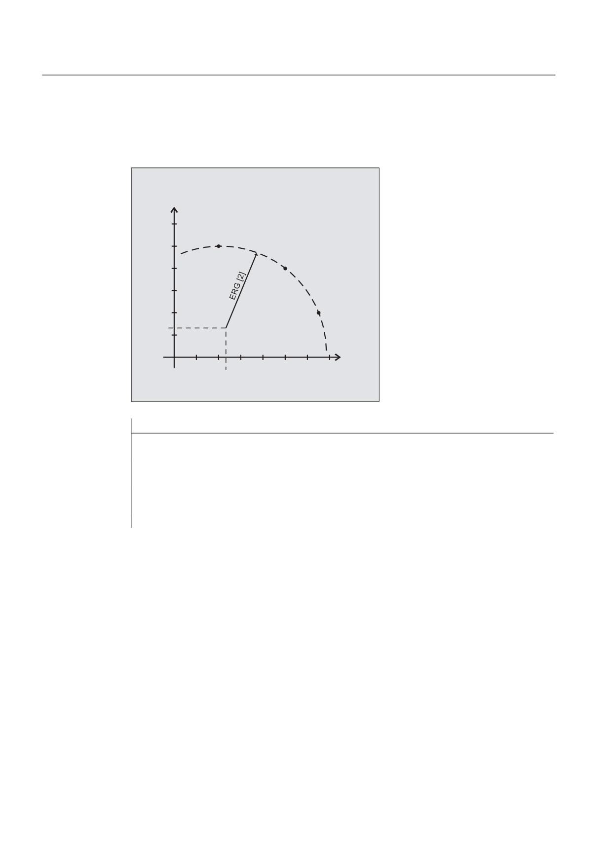
Using the CALCDAT command, you can calculate the radius and the circle center point
coordinates from the three or four points known along the circle The specified points must be
different. Where four points do not lie directly on the circle an average value is taken for the
circle center point and the radius.
Syntax
<Status>=CALCDAT(<circle points>[<number>,<type>],<number>,<result>)
Significance
CALCDAT
Command to calculate the radius and center point coordinates
of a circle from 3 or 4 points
<status>
Variable for the circle calculation status
Type:
BOOL
Value:
TRUE
The specified points lie on a circle.
FALSE
The specified points do not lie on a
circle.
<circle points>[]
Variable to specify the circle points
using parameters
<number>
Number of circle points (3 or 4)
<type>
Type of coordinate data,
e.g. 2 for 2-point coordinates
<number>
Parameter for the number of the points used for the calculation
(3 or 4)
<result>[3]
Variable for result:
Circle center point coordinates and radius
0
Circle center point coordinate: Abscissa value
1
Circle center point coordinate: Ordinate value
2
Radius
Note
Please note that the variables must be defined before they are used.
Job Planning
Programming Manual, 03/2010, 6FC5398-2BP20-1BA0
715
User stock removal programs
15.6 Calculate circle data (CALCDAT)
Example
Using three points it should be determined as to whether they are located on a circle
segment.
<
(5* > @
;
(5* > @
Program code
Comments
N10 DEF REAL PT[3,2]=(20,50,50,40,65,20)
; Variable to specify the points
along a circle
N20 DEF REAL RES[3]
; Variable for result
N30 DEF BOOL STATUS
; Variable for status
N40 STATUS=CALCDAT(PKT,3,ERG)
; Call the determined circle
data.
N50 IF STATUS == FALSE GOTOF ERROR
; Jump to error
Job Planning
716
Programming Manual, 03/2010, 6FC5398-2BP20-1BA0
User stock removal programs
15.7 Deactivate contour preparation (EXECUTE)
15.7
Deactivate contour preparation (EXECUTE)
Function
The command EXECUTE is used to deactivate the contour preparation and at the same time
the system returns to the normal execution mode.
Syntax
EXECUTE(<ERROR>)
Significance
EXECUTE
Command to terminate contour preparation
<FAULT>
Variable for the fault feedback signal
Type:
INT
The value of the variable indicates whether the contour was able to be
prepared error-free:
0
Errors
1
No error
Example
Program code
N30 CONTPRON(...)
N40 G1 X... Z
N100 EXECUTE(...)
Job Planning
Programming Manual, 03/2010, 6FC5398-2BP20-1BA0
717
User stock removal programs
15.7 Deactivate contour preparation (EXECUTE)
Job Planning
718
Programming Manual, 03/2010, 6FC5398-2BP20-1BA0
Tables
16
16.1
List of statements
Legend:
1)
Reference to the document containing the detailed description of the operation:
PGsl
Programming Manual, Fundamentals
PGAsl
Programming Manual, Job Planning
BHDsl
Operating Manual, Turning
BHFsl
Operating Manual, Milling
FB1 ( )
Function Manual, Basic Functions (with the alphanumeric abbreviation of the corresponding
function description in brackets)
FB2 ( )
Function Manual, Extended Functions (with the alphanumeric abbreviation of the corresponding
function description in brackets)
FB3 ( )
Function Manual, Special Functions (with the alphanumeric abbreviation of the corresponding
function description in brackets)
FBSIsl
Function Manual, Safety Integrated
FBSY
Function Manual, Synchronized Actions
FBW
Function Manual, Tool Management
2)
Effectiveness of the operation:
m
modal
s
non-modal
3)
Availability for SINUMERIK 828D (D = Turning, F = Milling):
●
Standard
○
Option
-
Not available
4)
Default setting at beginning of program (factory settings of the control, if nothing else programmed).
Operation
Meaning
Description see 1)
W 2)
828D 3)
PPU260 / 261
PPU280 / 281
D
F
D
F
:
NC main block number,
PGAsl
●
●
●
●
jump label termination,
Arithmetic functions (Page 61)
concatenation operator
*
Operator for multiplication
PGAsl
●
●
●
●
Arithmetic functions (Page 61)
+
Operator for addition
PGAsl
●
●
●
●
Arithmetic functions (Page 61)
Job Planning
Programming Manual, 03/2010, 6FC5398-2BP20-1BA0
719
Tables
16.1 List of statements
Operation
Meaning
Description see 1)
W 2)
828D 3)
PPU260 / 261
PPU280 / 281
D
F
D
F
-
Operator for subtraction
PGAsl
●
●
●
●
Arithmetic functions (Page 61)
<
Comparison operator,
PGAsl
●
●
●
●
less than
Arithmetic functions (Page 61)
<<
Concatenation operator
PGAsl
●
●
●
●
for strings
Arithmetic functions (Page 61)
<=
Comparison operator,
PGAsl
●
●
●
●
less than or equal to
Arithmetic functions (Page 61)
=
Assignment operator
PGAsl
●
●
●
●
Arithmetic functions (Page 61)
>=
Comparison operator,
PGAsl
●
●
●
●
greater than or equal to
Arithmetic functions (Page 61)
/
Operator for division
PGAsl
●
●
●
●
Arithmetic functions (Page 61)
/0
Block is skipped (1st skip
PGsl
●
●
●
●
…
level)
…
Block is skipped (8th skip
/7
level)
○
○
○
○
A
Axis name
PGAsl
m/s
●
●
●
●
Programming of the tool
orientation (A..., B..., C..., LEAD,
TILT) (Page 323)
A2
Tool orientation: RPY or
PGAsl
s
●
●
●
●
Euler angle
Programming of the tool
orientation (A..., B..., C..., LEAD,
TILT) (Page 323)
A3
Tool orientation:
PGAsl
s
●
●
●
●
Direction/surface normal
Programming of the tool
vector component
orientation (A..., B..., C..., LEAD,
TILT) (Page 323)
A4
Tool orientation: Surface
PGAsl
s
●
●
●
●
normal vector for
Face milling (3D-milling A4, B4,
beginning of block
C4, A5, B5, C5) (Page 329)
A5
Tool orientation: Surface
PGAsl
s
●
●
●
●
normal vector for end of
Face milling (3D-milling A4, B4,
block
C4, A5, B5, C5) (Page 329)
ABS
Absolute value (amount)
PGAsl
●
●
●
●
Arithmetic functions (Page 61)
AC
Absolute dimensions of
PGsl
s
●
●
●
●
coordinates/positions
ACC
Effect of current axial
PGsl
m
●
●
●
●
acceleration
Job Planning
720
Programming Manual, 03/2010, 6FC5398-2BP20-1BA0
Tables
16.1 List of statements
Operation
Meaning
Description see 1)
W 2)
828D 3)
PPU260 / 261
PPU280 / 281
D
F
D
F
ACCLIMA
Effect of current
PGsl
m
●
●
●
●
maximum axial
acceleration
ACN
Absolute dimensions for
PGsl
s
●
●
●
●
rotary axes, approach
position in negative
direction
ACOS
Arc cosine
PGAsl
●
●
●
●
(trigon. function)
Arithmetic functions (Page 61)
ACP
Absolute dimensions for
PGsl
s
●
●
●
●
rotary axes, approach
position in positive
direction
ACTBLOCNO
Output of current block
PGAsl
●
●
●
●
number of an alarm
Suppress current block display
block, even if "current
(DISPLOF, DISPLON,
block display
ACTBLOCNO) (Page 164)
suppressed" (DISPLOF)
is active.
ADDFRAME
Inclusion and possible
PGAsl, FB1(K2)
●
●
●
●
activation of a measured
Frame calculation from three
frame
measuring points in space
(MEAFRAME) (Page 298)
ADIS
Rounding clearance for
PGsl
m
●
●
●
●
path functions G1, G2,
G3, ...
ADISPOS
Rounding clearance for
PGsl
m
●
●
●
●
rapid traverse G0
ADISPOSA
Size of the tolerance
PGAsl
m
●
●
●
●
window for IPOBRKA
Programmed end-of-motion
criterion (FINEA, COARSEA,
IPOENDA, IPOBRKA,
ADISPOSA) (Page 274)
ALF
LIFTFAST angle
PGAsl
m
●
●
●
●
Fast retraction from the contour
(SETINT LIFTFAST, ALF)
(Page 115)
AMIRROR
Programmable mirroring
PGsl
s
●
●
●
●
AND
Logical AND
PGAsl
●
●
●
●
Comparison and logic
operations (Page 64)
ANG
Contour angle
PGsl
s
●
●
●
●
Job Planning
Programming Manual, 03/2010, 6FC5398-2BP20-1BA0
721
Tables
16.1 List of statements
Operation
Meaning
Description see 1)
W 2)
828D 3)
PPU260 / 261
PPU280 / 281
D
F
D
F
AP
Polar angle
PGsl
m/s
●
●
●
●
APR
Read/show access
PGAsl
●
●
●
●
protection
Attribute: Access rights (APR,
APW, APRP, APWP, APRB,
APWB) (Page 38)
APRB
Read access right, OPI
PGAsl
●
●
●
●
Attribute: Access rights (APR,
APW, APRP, APWP, APRB,
APWB) (Page 38)
APRP
Read access right, part
PGAsl
●
●
●
●
program
Attribute: Access rights (APR,
APW, APRP, APWP, APRB,
APWB) (Page 38)
APW
Write access protection
PGAsl
●
●
●
●
Attribute: Access rights (APR,
APW, APRP, APWP, APRB,
APWB) (Page 38)
APWB
Write access right, OPI
PGAsl
●
●
●
●
Attribute: Access rights (APR,
APW, APRP, APWP, APRB,
APWB) (Page 38)
APWP
Write access right, part
PGAsl
●
●
●
●
program
Attribute: Access rights (APR,
APW, APRP, APWP, APRB,
APWB) (Page 38)
APX
Definition of the access
PGAsl
●
●
●
●
right for executing the
Redefinition of system variables,
specified language
user variables, and NC
element
language commands (REDEF)
(Page 28)
AR
Opening angle
PGsl
m/s
●
●
●
●
AROT
Programmable rotation
PGsl
s
●
●
●
●
AROTS
Programmable frame
PGsl
s
●
●
●
●
rotations with solid angles
SL
Macro definition
PGAsl
●
●
●
●
Macro technique (DEFINE ...
AS) (Page 201)
ASCALE
Programmable scaling
PGsl
s
●
●
●
●
Job Planning
722
Programming Manual, 03/2010, 6FC5398-2BP20-1BA0
Tables
16.1 List of statements
Operation
Meaning
Description see 1)
W 2)
828D 3)
PPU260 / 261
PPU280 / 281
D
F
D
F
ASIN
Arithmetic function, arc
PGAsl
●
●
●
●
sine
Arithmetic functions (Page 61)
ASPLINE
Akima spline
PGAsl
m
-
○
-
○
Spline interpolation (ASPLINE,
BSPLINE, CSPLINE, BAUTO,
BNAT, BTAN, EAUTO, ENAT,
ETAN, PW, SD, PL) (Page 233)
ATAN2
Arc tangent 2
PGAsl
●
●
●
●
Arithmetic functions (Page 61)
ATOL
Axis-specific tolerance for
PGAsl
-
●
-
●
compressor functions,
Programmable
orientation smoothing
contour/orientation tolerance
and smoothing types
(CTOL, OTOL, ATOL)
(Page 491)
ATRANS
Additive programmable
PGsl
s
●
●
●
●
translation
AX
Variable axis identifier
PGAsl
m/s
●
●
●
●
Axis functions (AXNAME, AX,
SPI, AXTOSPI, ISAXIS,
AXSTRING, MODAXVAL)
(Page 669)
AXCTSWE
Advance container axis
PGAsl
-
-
-
-
Axis container (AXCTSWE,
AXCTSWED) (Page 677)
AXCTSWED
Rotate axis container
PGAsl
-
-
-
-
Axis container (AXCTSWE,
AXCTSWED) (Page 677)
AXIS
Axis identifier, axis
PGAsl
●
●
●
●
address
Definition of user variables
(DEF) (Page 22)
AXNAME
Converts input string into
PGAsl
●
●
●
●
axis identifier
Axis functions (AXNAME, AX,
SPI, AXTOSPI, ISAXIS,
AXSTRING, MODAXVAL)
(Page 669)
AXSTRING
Converts string spindle
PGAsl
●
●
●
●
number
Axis functions (AXNAME, AX,
SPI, AXTOSPI, ISAXIS,
AXSTRING, MODAXVAL)
(Page 669)
AXTOCHAN
Request axis for a
PGAsl
●
●
●
●
specific channel. Possible
Transfer axis to another channel
from NC program and
(AXTOCHAN) (Page 126)
synchronized action.
Job Planning
Programming Manual, 03/2010, 6FC5398-2BP20-1BA0
723
Tables
16.1 List of statements
Operation
Meaning
Description see 1)
W 2)
828D 3)
PPU260 / 261
PPU280 / 281
D
F
D
F
AXTOSPI
Converts axis identifier
PGAsl
●
●
●
●
into a spindle index
Axis functions (AXNAME, AX,
SPI, AXTOSPI, ISAXIS,
AXSTRING, MODAXVAL)
(Page 669)
B
Axis name
PGAsl
m/s
●
●
●
●
Programming of the tool
orientation (A..., B..., C..., LEAD,
TILT) (Page 323)
B2
Tool orientation: RPY or
PGAsl
s
●
●
●
●
Euler angle
Programming of the tool
orientation (A..., B..., C..., LEAD,
TILT) (Page 323)
B3
Tool orientation:
PGAsl
s
●
●
●
●
Direction/surface normal
Programming of the tool
vector component
orientation (A..., B..., C..., LEAD,
TILT) (Page 323)
B4
Tool orientation: Surface
PGAsl
s
●
●
●
●
normal vector for
Face milling (3D-milling A4, B4,
beginning of block
C4, A5, B5, C5) (Page 329)
B5
Tool orientation: Surface
PGAsl
s
●
●
●
●
normal vector for end of
Face milling (3D-milling A4, B4,
block
C4, A5, B5, C5) (Page 329)
B_AND
Bit AND
PGAsl
●
●
●
●
Comparison and logic
operations (Page 64)
B_OR
Bit OR
PGAsl
●
●
●
●
Comparison and logic
operations (Page 64)
B_NOT
Bit negation
PGAsl
●
●
●
●
Comparison and logic
operations (Page 64)
B_XOR
Bit exclusive OR
PGAsl
●
●
●
●
Comparison and logic
operations (Page 64)
BAUTO
Definition of the first
PGAsl
m
-
○
-
○
spline section by means
Spline interpolation (ASPLINE,
of the next 3 points
BSPLINE, CSPLINE, BAUTO,
BNAT, BTAN, EAUTO, ENAT,
ETAN, PW, SD, PL) (Page 233)
BLOCK
Together with the
PGAsl
●
●
●
●
keyword TO defines the
Indirect subprogram call with
program part to be
specification of the calling
processed in an indirect
program part (CALL BLOCK ...
subprogram call
TO ...) (Page 188)
Job Planning
724
Programming Manual, 03/2010, 6FC5398-2BP20-1BA0
Tables
16.1 List of statements
Operation
Meaning
Description see 1)
W 2)
828D 3)
PPU260 / 261
PPU280 / 281
D
F
D
F
BLSYNC
Processing of interrupt
PGAsl
●
●
●
●
routine is only to start
Assign and start interrupt routine
with the next block
(SETINT, PRIO, BLSYNC)
change
(Page 111)
BNAT 4)
Natural transition to first
PGAsl
m
-
○
-
○
spline block
Spline interpolation (ASPLINE,
BSPLINE, CSPLINE, BAUTO,
BNAT, BTAN, EAUTO, ENAT,
ETAN, PW, SD, PL) (Page 233)
BOOL
Data type: Boolean value
PGAsl
●
●
●
●
TRUE/FALSE or 1/0
Definition of user variables
(DEF) (Page 22)
BOUND
Tests whether the value
PGAsl
●
●
●
●
falls within the defined
Variable minimum, maximum
value range. If the values
and range (MINVAL, MAXVAL
are equal, the test value
and BOUND) (Page 68)
is returned.
BRISK 4)
Fast non-smoothed path
PGsl
m
●
●
●
●
acceleration
BRISKA
Switch on brisk path
PGsl
●
●
●
●
acceleration for the
programmed axes
BSPLINE
B-spline
PGAsl
m
-
○
-
○
Spline interpolation (ASPLINE,
BSPLINE, CSPLINE, BAUTO,
BNAT, BTAN, EAUTO, ENAT,
ETAN, PW, SD, PL) (Page 233)
BTAN
Tangential transition to
PGAsl
m
-
○
-
○
first spline block
Spline interpolation (ASPLINE,
BSPLINE, CSPLINE, BAUTO,
BNAT, BTAN, EAUTO, ENAT,
ETAN, PW, SD, PL) (Page 233)
C
Axis name
PGAsl
m/s
●
●
●
●
Programming of the tool
orientation (A..., B..., C..., LEAD,
TILT) (Page 323)
C2
Tool orientation: RPY or
PGAsl
s
●
●
●
●
Euler angle
Programming of the tool
orientation (A..., B..., C..., LEAD,
TILT) (Page 323)
C3
Tool orientation:
PGAsl
s
●
●
●
●
Direction/surface normal
Programming of the tool
vector component
orientation (A..., B..., C..., LEAD,
TILT) (Page 323)
Job Planning
Programming Manual, 03/2010, 6FC5398-2BP20-1BA0
725
Tables
16.1 List of statements
Operation
Meaning
Description see 1)
W 2)
828D 3)
PPU260 / 261
PPU280 / 281
D
F
D
F
C4
Tool orientation: Surface
PGAsl
s
●
●
●
●
normal vector for
Face milling (3D-milling A4, B4,
beginning of block
C4, A5, B5, C5) (Page 329)
C5
Tool orientation: Surface
PGAsl
s
●
●
●
●
normal vector for end of
Face milling (3D-milling A4, B4,
block
C4, A5, B5, C5) (Page 329)
CAC
Absolute position
PGAsl
●
●
●
●
approach
Approaching coded positions
(CAC, CIC, CDC, CACP, CACN)
(Page 231)
CACN
Absolute approach of the
PGAsl
●
●
●
●
value listed in the table in
Approaching coded positions
negative direction
(CAC, CIC, CDC, CACP, CACN)
(Page 231)
CACP
Absolute approach of the
PGAsl
●
●
●
●
value listed in the table in
Approaching coded positions
positive direction
(CAC, CIC, CDC, CACP, CACN)
(Page 231)
CALCDAT
Calculates radius and
PGAsl
●
●
●
●
center point of circle from
Calculate circle data
3 or 4 points
(CALCDAT) (Page 715)
CALCPOSI
Checking for protection
PGAsl
●
●
●
●
zone violation, working
Checking for protection zone
area limitation and
violation, working area limitation
software limits
and software limits (CALCPOSI)
(Page 223)
CALL
Indirect subroutine call
PGAsl
●
●
●
●
Indirect subprogram call (CALL)
(Page 187)
CALLPATH
Programmable search
PGAsl
●
●
●
●
path for subroutine calls
Extend search path for
subprogram calls (CALLPATH)
(Page 192)
CANCEL
Cancel modal
PGAsl
●
●
●
●
synchronized action
Delete synchronized action
(CANCEL) (Page 636)
CASE
Conditional program
PGAsl
●
●
●
●
branch
Program branch (CASE ... OF ...
DEFAULT ...) (Page 86)
CDC
Direct approach of a
PGAsl
●
●
●
●
position
Approaching coded positions
(CAC, CIC, CDC, CACP, CACN)
(Page 231)
Job Planning
726
Programming Manual, 03/2010, 6FC5398-2BP20-1BA0
Tables
16.1 List of statements
Operation
Meaning
Description see 1)
W 2)
828D 3)
PPU260 / 261
PPU280 / 281
D
F
D
F
CDOF 4)
Collision detection OFF
PGsl
m
●
●
●
●
CDOF2
Collision detection OFF,
PGsl
m
●
●
●
●
for 3D circumferential
milling
CDON
Collision detection ON
PGsl
m
●
●
●
●
CFC 4)
Constant feedrate on
PGsl
m
●
●
●
●
contour
CFIN
Constant feedrate for
PGsl
m
●
●
●
●
internal radius only, not
for external radius
CFINE
Assignment of fine offset
PGAsl
●
●
●
●
to a FRAME variable
Coarse and fine offsets (CFINE,
CTRANS) (Page 293)
CFTCP
Constant feedrate in tool
PGsl
m
●
●
●
●
center point (center point
path)
CHAN
Specify validity range for
PGAsl
●
●
●
●
data
Definition of user variables
(DEF) (Page 22)
CHANDATA
Set channel number for
PGAsl
●
●
●
●
channel data access
Working memory (CHANDATA,
COMPLETE, INITIAL)
(Page 210)
CHAR
Data type: ASCII
PGAsl
●
●
●
●
character
Definition of user variables
(DEF) (Page 22)
CHECKSUM
Forms the checksum
PGAsl
●
●
●
●
over an array as a fixed-
Checksum calculation using an
length STRING
array (CHECKSUM) (Page 142)
CHF
Chamfer;
PGsl
s
●
●
●
●
value = length of chamfer
CHKDM
Uniqueness check within
FBW
●
●
●
●
a magazine
CHKDNO
Check for unique D
PGAsl
●
●
●
●
numbers
Free assignment of D numbers:
Checking D numbers
(CHKDNO) (Page 430)
Job Planning
Programming Manual, 03/2010, 6FC5398-2BP20-1BA0
727
Tables
16.1 List of statements
Operation
Meaning
Description see 1)
W 2)
828D 3)
PPU260 / 261
PPU280 / 281
D
F
D
F
CHR
Chamfer;
PGsl
●
●
●
●
value = length of chamfer
in direction of movement
CIC
Approach position by
PGAsl
●
●
●
●
increments
Approaching coded positions
(CAC, CIC, CDC, CACP, CACN)
(Page 231)
CIP
Circular interpolation
PGsl
m
●
●
●
●
through intermediate
point
CLEARM
Reset one/several
PGAsl
-
-
-
-
markers for channel
Program coordination (INIT,
coordination
START, WAITM, WAITMC,
WAITE, SETM, CLEARM)
(Page 103)
CLRINT
Deselect interrupt
PGAsl
●
●
●
●
Delete assignment of interrupt
routine (CLRINT) (Page 114)
CMIRROR
Mirror on a coordinate
PGAsl
●
●
●
●
axis
Arithmetic functions (Page 61)
COARSEA
Motion end when "Exact
PGAsl
m
●
●
●
●
stop coarse" reached
Programmed end-of-motion
criterion (FINEA, COARSEA,
IPOENDA, IPOBRKA,
ADISPOSA) (Page 274)
COMPCAD
Compressor ON:
PGAsl
m
-
○
-
○
Optimum surface quality
NC block compression
for CAD programs
(COMPON, COMPCURV,
COMPCAD, COMPOF)
(Page 247)
COMPCURV
Compressor ON:
PGAsl
m
-
○
-
○
Polynomials with
NC block compression
constant curvature
(COMPON, COMPCURV,
COMPCAD, COMPOF)
(Page 247)
COMPLETE
Control instruction for
PGAsl
●
●
●
●
reading and writing data
Working memory (CHANDATA,
COMPLETE, INITIAL)
(Page 210)
COMPOF 4)
Compressor OFF
PGAsl
m
-
○
-
○
NC block compression
(COMPON, COMPCURV,
COMPCAD, COMPOF)
(Page 247)
Job Planning
728
Programming Manual, 03/2010, 6FC5398-2BP20-1BA0
Tables
16.1 List of statements
Operation
Meaning
Description see 1)
W 2)
828D 3)
PPU260 / 261
PPU280 / 281
D
F
D
F
COMPON
Compressor ON
PGAsl
-
○
-
○
NC block compression
(COMPON, COMPCURV,
COMPCAD, COMPOF)
(Page 247)
CONTDCON
Tabular contour decoding
PGAsl
●
●
●
●
ON
Generate coded contour table
(CONTDCON) (Page 708)
CONTPRON
Activate reference
PGAsl
●
●
●
●
preprocessing
Generate contour table
(CONTPRON) (Page 702)
CORROF
All active overlaid
PGsl
●
●
●
●
movements are
deselected
COS
Cosine
PGAsl
●
●
●
●
(trigon. function)
Arithmetic functions (Page 61)
COUPDEF
Definition ELG
PGAsl
○
-
○
-
group/synchronous
Synchronous spindle:
spindle group
Programming (COUPDEF,
COUPDEL, COUPON,
COUPONC, COUPOF,
COUPOFS, COUPRES,
WAITC) (Page 535)
COUPDEL
Delete ELG group
PGAsl
○
-
○
-
Synchronous spindle:
Programming (COUPDEF,
COUPDEL, COUPON,
COUPONC, COUPOF,
COUPOFS, COUPRES,
WAITC) (Page 535)
COUPOF
ELG group/synchronous
PGAsl
○
-
○
-
spindle pair ON
Synchronous spindle:
Programming (COUPDEF,
COUPDEL, COUPON,
COUPONC, COUPOF,
COUPOFS, COUPRES,
WAITC) (Page 535)
COUPOFS
Deactivate ELG
PGAsl
○
-
○
-
group/synchronous
Synchronous spindle:
spindle pair with stop of
Programming (COUPDEF,
following spindle
COUPDEL, COUPON,
COUPONC, COUPOF,
COUPOFS, COUPRES,
WAITC) (Page 535)
Job Planning
Programming Manual, 03/2010, 6FC5398-2BP20-1BA0
729
Tables
16.1 List of statements
Operation
Meaning
Description see 1)
W 2)
828D 3)
PPU260 / 261
PPU280 / 281
D
F
D
F
COUPON
ELG group/synchronous
PGAsl
○
-
○
-
spindle pair ON
Synchronous spindle:
Programming (COUPDEF,
COUPDEL, COUPON,
COUPONC, COUPOF,
COUPOFS, COUPRES,
WAITC) (Page 535)
COUPONC
Transfer activation of
PGAsl
○
-
○
-
ELG group/synchronous
Synchronous spindle:
spindle pair with previous
Programming (COUPDEF,
programming
COUPDEL, COUPON,
COUPONC, COUPOF,
COUPOFS, COUPRES,
WAITC) (Page 535)
COUPRES
Reset ELG group
PGAsl
○
-
○
-
Synchronous spindle:
Programming (COUPDEF,
COUPDEL, COUPON,
COUPONC, COUPOF,
COUPOFS, COUPRES,
WAITC) (Page 535)
CP
Path motion
PGAsl
m
●
●
●
●
Cartesian PTP travel
(Page 376)
CPRECOF 4)
Programmable contour
PGsl
m
●
●
●
●
accuracy OFF
CPRECON
Programmable contour
PGsl
m
●
●
●
●
accuracy ON
CPROT
Channel-specific
PGAsl
●
●
●
●
protection zone ON/OFF
Activating/deactivating
protection zones (CPROT,
NPROT) (Page 219)
CPROTDEF
Definition of a channel-
PGAsl
●
●
●
●
specific protection zone
Definition of the protection
zones (CPROTDEF,
NPROTDEF) (Page 215)
CR
Circle radius
PGsl
s
●
●
●
●
CROT
Rotation of the current
PGAsl
●
●
●
●
coordinate system
Arithmetic functions (Page 61)
CROTS
Programmable frame
PGsl
s
●
●
●
●
rotations with solid angles
(rotation in the specified
axes)
CRPL
Frame rotation in any
FB1(K2)
●
●
●
●
plane
Job Planning
730
Programming Manual, 03/2010, 6FC5398-2BP20-1BA0
Tables
16.1 List of statements
Operation
Meaning
Description see 1)
W 2)
828D 3)
PPU260 / 261
PPU280 / 281
D
F
D
F
CSCALE
Scale factor for multiple
PGAsl
●
●
●
●
axes
Arithmetic functions (Page 61)
CSPLINE
Cubic spline
PGAsl
m
-
○
-
○
Spline interpolation (ASPLINE,
BSPLINE, CSPLINE, BAUTO,
BNAT, BTAN, EAUTO, ENAT,
ETAN, PW, SD, PL) (Page 233)
CT
Circle with tangential
PGsl
m
●
●
●
●
transition
CTAB
Define following axis
PGAsl
-
-
-
-
position according to
Read curve table values
leading axis position from
(CTABTSV, CTABTEV,
curve table
CTABTSP, CTABTEP,
CTABSSV, CTABSEV, CTAB,
CTABINV, CTABTMIN,
CTABTMAX) (Page 513)
CTABDEF
Table definition ON
PGAsl
-
-
-
-
Define curve tables (CTABDEF,
CATBEND) (Page 502)
CTABDEL
Clear curve table
PGAsl
-
-
-
-
Delete curve tables (CTABDEL)
(Page 508)
CTABEND
Table definition OFF
PGAsl
-
-
-
-
Define curve tables (CTABDEF,
CATBEND) (Page 502)
CTABEXISTS
Checks the curve table
PGAsl
-
-
-
-
with number n
Check for presence of curve
table (CTABEXISTS)
(Page 508)
CTABFNO
Number of curve tables
PGAsl
-
-
-
-
still possible in the
Curve tables: Check use of
memory
resources (CTABNO,
CTABNOMEM, CTABFNO,
CTABSEGID, CTABSEG,
CTABFSEG, CTABMSEG,
CTABPOLID, CTABPOL,
CTABFPOL, CTABMPOL)
(Page 518)
Job Planning
Programming Manual, 03/2010, 6FC5398-2BP20-1BA0
731
Tables
16.1 List of statements
Operation
Meaning
Description see 1)
W 2)
828D 3)
PPU260 / 261
PPU280 / 281
D
F
D
F
CTABFPOL
Number of polynomials
PGAsl
-
-
-
-
still possible in the
Curve tables: Check use of
memory
resources (CTABNO,
CTABNOMEM, CTABFNO,
CTABSEGID, CTABSEG,
CTABFSEG, CTABMSEG,
CTABPOLID, CTABPOL,
CTABFPOL, CTABMPOL)
(Page 518)
CTABFSEG
Number of curve
PGAsl
-
-
-
-
segments still possible in
Curve tables: Check use of
the memory
resources (CTABNO,
CTABNOMEM, CTABFNO,
CTABSEGID, CTABSEG,
CTABFSEG, CTABMSEG,
CTABPOLID, CTABPOL,
CTABFPOL, CTABMPOL)
(Page 518)
CTABID
Returns table number of
PGAsl
-
-
-
-
the nth curve table
Curve tables: Determine table
properties (CTABID,
CTABISLOCK, CTABMEMTYP,
CTABPERIOD) (Page 511)
CTABINV
Define leading axis
PGAsl
-
-
-
-
position according to
Read curve table values
following axis position
(CTABTSV, CTABTEV,
from curve table
CTABTSP, CTABTEP,
CTABSSV, CTABSEV, CTAB,
CTABINV, CTABTMIN,
CTABTMAX) (Page 513)
CTABISLOCK
Returns the lock state of
PGAsl
-
-
-
-
the curve table with
Curve tables: Determine table
number n
properties (CTABID,
CTABISLOCK, CTABMEMTYP,
CTABPERIOD) (Page 511)
CTABLOCK
Delete and overwrite,
PGAsl
-
-
-
-
lock
Locking curve tables to prevent
deletion and overwriting
(CTABLOCK, CTABUNLOCK)
(Page 510)
CTABMEMTYP
Returns the memory in
PGAsl
-
-
-
-
which curve table number
Curve tables: Determine table
n is created
properties (CTABID,
CTABISLOCK, CTABMEMTYP,
CTABPERIOD) (Page 511)
Job Planning
732
Programming Manual, 03/2010, 6FC5398-2BP20-1BA0
Tables
16.1 List of statements
Operation
Meaning
Description see 1)
W 2)
828D 3)
PPU260 / 261
PPU280 / 281
D
F
D
F
CTABMPOL
Max. number of
PGAsl
-
-
-
-
polynomials still possible
Curve tables: Check use of
in the memory
resources (CTABNO,
CTABNOMEM, CTABFNO,
CTABSEGID, CTABSEG,
CTABFSEG, CTABMSEG,
CTABPOLID, CTABPOL,
CTABFPOL, CTABMPOL)
(Page 518)
CTABMSEG
Max. number of curve
PGAsl
-
-
-
-
segments still possible in
Curve tables: Check use of
the memory
resources (CTABNO,
CTABNOMEM, CTABFNO,
CTABSEGID, CTABSEG,
CTABFSEG, CTABMSEG,
CTABPOLID, CTABPOL,
CTABFPOL, CTABMPOL)
(Page 518)
CTABNO
Number of defined curve
FB3(M3)
-
-
-
-
tables in SRAM or DRAM
CTABNOMEM
Number of defined curve
PGAsl
-
-
-
-
tables in SRAM or DRAM
Curve tables: Check use of
resources (CTABNO,
CTABNOMEM, CTABFNO,
CTABSEGID, CTABSEG,
CTABFSEG, CTABMSEG,
CTABPOLID, CTABPOL,
CTABFPOL, CTABMPOL)
(Page 518)
CTABPERIOD
Returns the table
PGAsl
-
-
-
-
periodicity of curve table
Curve tables: Determine table
number n
properties (CTABID,
CTABISLOCK, CTABMEMTYP,
CTABPERIOD) (Page 511)
CTABPOL
Number of polynomials
PGAsl
-
-
-
-
already used in the
Curve tables: Check use of
memory
resources (CTABNO,
CTABNOMEM, CTABFNO,
CTABSEGID, CTABSEG,
CTABFSEG, CTABMSEG,
CTABPOLID, CTABPOL,
CTABFPOL, CTABMPOL)
(Page 518)
Job Planning
Programming Manual, 03/2010, 6FC5398-2BP20-1BA0
733
Tables
16.1 List of statements
Operation
Meaning
Description see 1)
W 2)
828D 3)
PPU260 / 261
PPU280 / 281
D
F
D
F
CTABPOLID
Number of the curve
PGAsl
-
-
-
-
polynomials used by the
Curve tables: Check use of
curve table with number n
resources (CTABNO,
CTABNOMEM, CTABFNO,
CTABSEGID, CTABSEG,
CTABFSEG, CTABMSEG,
CTABPOLID, CTABPOL,
CTABFPOL, CTABMPOL)
(Page 518)
CTABSEG
Number of curve
PGAsl
-
-
-
-
segments already used in
Curve tables: Check use of
the memory
resources (CTABNO,
CTABNOMEM, CTABFNO,
CTABSEGID, CTABSEG,
CTABFSEG, CTABMSEG,
CTABPOLID, CTABPOL,
CTABFPOL, CTABMPOL)
(Page 518)
CTABSEGID
Number of the curve
PGAsl
-
-
-
-
segments used by the
Curve tables: Check use of
curve table with number n
resources (CTABNO,
CTABNOMEM, CTABFNO,
CTABSEGID, CTABSEG,
CTABFSEG, CTABMSEG,
CTABPOLID, CTABPOL,
CTABFPOL, CTABMPOL)
(Page 518)
CTABSEV
Returns the final value of
PGAsl
-
-
-
-
the following axis of a
Read curve table values
segment of the curve
(CTABTSV, CTABTEV,
table
CTABTSP, CTABTEP,
CTABSSV, CTABSEV, CTAB,
CTABINV, CTABTMIN,
CTABTMAX) (Page 513)
CTABSSV
Returns the initial value
PGAsl
-
-
-
-
of the following axis of a
Read curve table values
segment of the curve
(CTABTSV, CTABTEV,
table
CTABTSP, CTABTEP,
CTABSSV, CTABSEV, CTAB,
CTABINV, CTABTMIN,
CTABTMAX) (Page 513)
CTABTEP
Returns the value of the
PGAsl
-
-
-
-
leading axis at curve
Read curve table values
table end
(CTABTSV, CTABTEV,
CTABTSP, CTABTEP,
CTABSSV, CTABSEV, CTAB,
CTABINV, CTABTMIN,
CTABTMAX) (Page 513)
Job Planning
734
Programming Manual, 03/2010, 6FC5398-2BP20-1BA0
Tables
16.1 List of statements
Operation
Meaning
Description see 1)
W 2)
828D 3)
PPU260 / 261
PPU280 / 281
D
F
D
F
CTABTEV
Returns the value of the
PGAsl
-
-
-
-
the following axis at curve
Read curve table values
table end
(CTABTSV, CTABTEV,
CTABTSP, CTABTEP,
CTABSSV, CTABSEV, CTAB,
CTABINV, CTABTMIN,
CTABTMAX) (Page 513)
CTABTMAX
Returns the maximum
PGAsl
-
-
-
-
value of the following axis
Read curve table values
of the curve table
(CTABTSV, CTABTEV,
CTABTSP, CTABTEP,
CTABSSV, CTABSEV, CTAB,
CTABINV, CTABTMIN,
CTABTMAX) (Page 513)
CTABTMIN
Returns the minimum
PGAsl
-
-
-
-
value of the following axis
Read curve table values
of the curve table
(CTABTSV, CTABTEV,
CTABTSP, CTABTEP,
CTABSSV, CTABSEV, CTAB,
CTABINV, CTABTMIN,
CTABTMAX) (Page 513)
CTABTSP
Returns the value of the
PGAsl
-
-
-
-
leading axis at curve
Read curve table values
table start
(CTABTSV, CTABTEV,
CTABTSP, CTABTEP,
CTABSSV, CTABSEV, CTAB,
CTABINV, CTABTMIN,
CTABTMAX) (Page 513)
CTABTSV
Returns the value of the
PGAsl
-
-
-
-
following axis at curve
Read curve table values
table start
(CTABTSV, CTABTEV,
CTABTSP, CTABTEP,
CTABSSV, CTABSEV, CTAB,
CTABINV, CTABTMIN,
CTABTMAX) (Page 513)
CTABUNLOCK
Revoke delete and
PGAsl
-
-
-
-
overwrite lock
Locking curve tables to prevent
deletion and overwriting
(CTABLOCK, CTABUNLOCK)
(Page 510)
CTOL
Contour tolerance for
PGAsl
-
○
-
○
compressor functions,
Programmable
orientation smoothing
contour/orientation tolerance
and smoothing types
(CTOL, OTOL, ATOL)
(Page 491)
CTRANS
Zero offset for multiple
PGAsl
●
●
●
●
axes
Coarse and fine offsets (CFINE,
CTRANS) (Page 293)
Job Planning
Programming Manual, 03/2010, 6FC5398-2BP20-1BA0
735
Tables
16.1 List of statements
Operation
Meaning
Description see 1)
W 2)
828D 3)
PPU260 / 261
PPU280 / 281
D
F
D
F
CUT2D 4)
2D tool offset
PGsl
m
●
●
●
●
CUT2DF
2D tool offset The tool
PGsl
m
●
●
●
●
offset is applied relative
to the current frame
(inclined plane).
CUT3DC
3D tool offset
PGAsl
m
-
-
-
-
circumferential milling
Activate 3D tool offsets
(CUT3DC..., CUT3DF...)
(Page 409)
CUT3DCC
3D tool offset
PGAsl
m
-
-
-
-
circumferential milling
3D tool offset Taking into
with limitation surfaces
consideration a limitation
surface (CUT3DCC,
CUT3DCCD) (Page 419)
CUT3DCCD
3D tool offset
PGAsl
m
-
-
-
-
circumferential milling
3D tool offset Taking into
with limitation surfaces
consideration a limitation
with differential tool
surface (CUT3DCC,
CUT3DCCD) (Page 419)
CUT3DF
3D tool offset face milling
PGAsl
m
-
-
-
-
Activate 3D tool offsets
(CUT3DC..., CUT3DF...)
(Page 409)
CUT3DFF
3D tool offset face milling
PGAsl
m
-
-
-
-
with constant tool
Activate 3D tool offsets
orientation dependent on
(CUT3DC..., CUT3DF...)
active frame
(Page 409)
CUT3DFS
3D tool offset face milling
PGAsl
m
-
-
-
-
with constant tool
Activate 3D tool offsets
orientation independent
(CUT3DC..., CUT3DF...)
of active frame
(Page 409)
CUTCONOF 4)
Constant radius
PGsl
m
●
●
●
●
compensation OFF
CUTCONON
Constant radius
PGsl
m
●
●
●
●
compensation ON
CUTMOD
Activate "Modification of
PGAsl
●
●
●
●
the offset data for
Cutting data modification for
rotatable tools"
tools that can be rotated
(CUTMOD) (Page 446)
CYCLE...
Measuring cycles
BHDsl/BHFsl
Job Planning
736
Programming Manual, 03/2010, 6FC5398-2BP20-1BA0
Tables
16.1 List of statements
Operation
Meaning
Description see 1)
W 2)
828D 3)
PPU260 / 261
PPU280 / 281
D
F
D
F
D
Tool offset number
PGsl
●
●
●
●
D0
With D0, offsets for the
PGsl
●
●
●
●
tool are ineffective.
DAC
Absolute non-modal axis-
PGsl
s
●
●
●
●
specific diameter
programming
DC
Absolute dimensions for
PGsl
s
●
●
●
●
rotary axes, approach
position directly
DEF
Variable definition
PGAsl
●
●
●
●
Definition of user variables
(DEF) (Page 22)
DEFINE
Keyword for macro
PGAsl
●
●
●
●
definitions
Macro technique (DEFINE ...
AS) (Page 201)
DEFAULT
Branch in CASE branch
PGAsl
●
●
●
●
Program branch (CASE ... OF ...
DEFAULT ...) (Page 86)
DELAYFSTON
Define the start of a stop
PGAsl
m
●
●
●
●
delay section
Program branch (CASE ... OF ...
DEFAULT ...) (Page 86)
DELAYFSTOF
Define the end of a stop
PGAsl
m
●
●
●
●
delay section
Conditionally interruptible
program sections
(DELAYFSTON, DELAYFSTOF)
(Page 468)
DELDL
Delete additive offsets
PGAsl
●
●
●
●
Delete additive offsets (DELDL)
(Page 395)
DELDTG
Deletion of distance-to-go
PGAsl
●
●
●
●
Delete distance-to-go (DELDTG)
(Page 582)
DELETE
Delete the specified file.
PGAsl
●
●
●
●
The file name can be
Delete file (DELETE)
specified with path and
(Page 132)
file identifier.
Job Planning
Programming Manual, 03/2010, 6FC5398-2BP20-1BA0
737
Tables
16.1 List of statements
Operation
Meaning
Description see 1)
W 2)
828D 3)
PPU260 / 261
PPU280 / 281
D
F
D
F
DELTOOLENV
Delete data records
FB1(W1)
●
●
●
●
describing tool
environments
DIACYCOFA
Axis-specific modal
FB1(P1)
m
●
●
●
●
diameter programming:
OFF in cycles
DIAM90
Diameter programming
PGAsl
m
●
●
●
●
for G90, radius
programming for G91
DIAM90A
Axis-specific modal
PGsl
m
●
●
●
●
diameter programming
for G90 and AC, radius
programming for G91 and
IC
DIAMCHAN
Transfer of all axes from
PGsl
●
●
●
●
MD axis functions to
diameter programming
channel status
DIAMCHANA
Transfer of the diameter
PGsl
●
●
●
●
programming channel
status
DIAMCYCOF
Channel-specific
FB1(P1)
m
●
●
●
●
diameter programming:
OFF in cycles
DIAMOF 4)
Diameter programming:
PGsl
m
●
●
●
●
OFF
Normal position, see
machine manufacturer
DIAMOFA
Axis-specific modal
PGsl
m
●
●
●
●
diameter programming:
OFF
Normal position, see
machine manufacturer
DIAMON
Diameter programming:
PGsl
m
●
●
●
●
ON
DIAMONA
Axis-specific modal
PGsl
m
●
●
●
●
diameter programming:
ON
Activation, see machine
manufacturer
Job Planning
738
Programming Manual, 03/2010, 6FC5398-2BP20-1BA0
Tables
16.1 List of statements
Operation
Meaning
Description see 1)
W 2)
828D 3)
PPU260 / 261
PPU280 / 281
D
F
D
F
DIC
Relative non-modal axis-
PGsl
s
●
●
●
●
specific diameter
programming
DILF
Retraction path (length)
PGsl
m
●
●
●
●
DISABLE
Interrupt OFF
PGAsl
●
●
●
●
Deactivating/reactivating the
assignment of an interrupt
routine (DISABLE, ENABLE)
(Page 113)
DISC
Transition circle
PGsl
m
●
●
●
●
overshoot tool radius
compensation
DISCL
Clearance between the
PGsl
●
●
●
●
end point of the fast
infeed motion and the
machining plane
DISPLOF
Suppress current block
PGAsl
●
●
●
●
display
Suppress current block display
(DISPLOF, DISPLON,
ACTBLOCNO) (Page 164)
DISPLON
Revoke suppression of
PGAsl
●
●
●
●
the current block display
Suppress current block display
(DISPLOF, DISPLON,
ACTBLOCNO) (Page 164)
DISPR
Path differential for
PGAsl
s
●
●
●
●
repositioning
Repositioning to a contour
(REPOSA, REPOSL, REPOSQ,
REPOSQA, REPOSH,
REPOSHA, DISR, DISPR, RMI,
RMB, RME, RMN) (Page 476)
DISR
Distance for repositioning
PGAsl
s
●
●
●
●
Repositioning to a contour
(REPOSA, REPOSL, REPOSQ,
REPOSQA, REPOSH,
REPOSHA, DISR, DISPR, RMI,
RMB, RME, RMN) (Page 476)
DITE
Thread run-out path
PGsl
m
●
●
●
●
DITS
Thread run-in path
PGsl
m
●
●
●
●
DIV
Integer division
PGAsl
●
●
●
●
Arithmetic functions (Page 61)
Job Planning
Programming Manual, 03/2010, 6FC5398-2BP20-1BA0
739
Tables
16.1 List of statements
Operation
Meaning
Description see 1)
W 2)
828D 3)
PPU260 / 261
PPU280 / 281
D
F
D
F
DL
Select location-
PGAsl
m
-
-
-
-
dependent additive tool
Selecting additive offsets (DL)
offset (DL, total set-up
(Page 392)
offset)
DO
Keyword for
PGAsl
●
●
●
●
synchronized action,
Actions (DO) (Page 557)
triggers action when
condition is fulfilled
DRFOF
Deactivation of
PGsl
m
●
●
●
●
handwheel offsets (DRF)
DRIVE
Velocity-dependent path
PGsl
m
●
●
●
●
acceleration
DRIVEA
Activate bent acceleration
PGsl
●
●
●
●
characteristic curve for
the programmed axes
DYNFINISH
Dynamic response for
PGsl
m
●
●
●
●
smooth finishing
DYNNORM
Standard dynamic
PGsl
m
●
●
●
●
response
DYNPOS
Dynamic response for
PGsl
m
●
●
●
●
positioning mode, tapping
DYNROUGH
Dynamic response for
PGsl
m
●
●
●
●
roughing
DYNSEMIFIN
Dynamic response for
PGsl
m
●
●
●
●
finishing
DZERO
Marks all D numbers of
PGAsl
●
●
●
●
the TO unit as invalid
Free assignment of D numbers:
Invalidate D numbers (DZERO)
(Page 433)
EAUTO
Definition of the last
PGAsl
m
-
○
-
○
spline section by means
Spline interpolation (ASPLINE,
of the last 3 points
BSPLINE, CSPLINE, BAUTO,
BNAT, BTAN, EAUTO, ENAT,
ETAN, PW, SD, PL) (Page 233)
EGDEF
Definition of an electronic
PGAsl
-
-
-
-
gear
Defining an electronic gear
(EGDEF) (Page 526)
EGDEL
Delete coupling definition
PGAsl
-
-
-
-
for the following axis
Deleting the definition of an
electronic gear (EGDEL)
(Page 532)
Job Planning
740
Programming Manual, 03/2010, 6FC5398-2BP20-1BA0
Tables
16.1 List of statements
Operation
Meaning
Description see 1)
W 2)
828D 3)
PPU260 / 261
PPU280 / 281
D
F
D
F
EGOFC
Turn off electronic gear
PGAsl
-
-
-
-
continuously
Switching-in the electronic
gearbox (EGOFS, EGOFC)
(Page 531)
EGOFS
Turn off electronic gear
PGAsl
-
-
-
-
selectively
Switching-in the electronic
gearbox (EGOFS, EGOFC)
(Page 531)
EGON
Turn on electronic gear
PGAsl
-
-
-
-
Switching-in the electronic
gearbox (EGOFS, EGOFC)
(Page 531)
EGONSYN
Turn on electronic gear
PGAsl
-
-
-
-
Switching-in the electronic
gearbox (EGOFS, EGOFC)
(Page 531)
EGONSYNE
Turn on electronic gear,
PGAsl
-
-
-
-
with specification of
Switching-in the electronic
approach mode
gearbox (EGOFS, EGOFC)
(Page 531)
ELSE
Program branch, if IF
PGAsl
●
●
●
●
condition not fulfilled
Program loop with alternative
(IF, ELSE, ENDIF) (Page 96)
ENABLE
Interrupt ON
PGAsl
●
●
●
●
Deactivating/reactivating the
assignment of an interrupt
routine (DISABLE, ENABLE)
(Page 113)
ENAT 4)
Natural transition to next
PGAsl
m
-
○
-
○
traversing block
Spline interpolation (ASPLINE,
BSPLINE, CSPLINE, BAUTO,
BNAT, BTAN, EAUTO, ENAT,
ETAN, PW, SD, PL) (Page 233)
ENDFOR
End line of FOR counter
PGAsl
●
●
●
●
loop
Count loop (FOR ... TO ...,
ENDFOR) (Page 99)
ENDIF
End line of IF branch
PGAsl
●
●
●
●
Program loop with alternative
(IF, ELSE, ENDIF) (Page 96)
ENDLABEL
End label for part
PGAsl, FB1(K1)
●
●
●
●
program repetitions with
Repeat program section
REPEAT
(REPEAT, REPEATB,
ENDLABEL, P) (Page 88)
Job Planning
Programming Manual, 03/2010, 6FC5398-2BP20-1BA0
741
Tables
16.1 List of statements
Operation
Meaning
Description see 1)
W 2)
828D 3)
PPU260 / 261
PPU280 / 281
D
F
D
F
ENDLOOP
End line of endless
PGAsl
●
●
●
●
program loop LOOP
Continuous program loop
(LOOP, ENDLOOP) (Page 98)
ENDPROC
End line of program with
●
●
●
●
start line PROC
ENDWHILE
End line of WHILE loop
PGAsl
●
●
●
●
Program loop with condition at
start of loop (WHILE,
ENDWHILE) (Page 100)
ETAN
Tangential transition to
PGAsl
m
-
○
-
○
next traversing block at
Spline interpolation (ASPLINE,
spline begin
BSPLINE, CSPLINE, BAUTO,
BNAT, BTAN, EAUTO, ENAT,
ETAN, PW, SD, PL) (Page 233)
EVERY
Execute synchronized
PGAsl
●
●
●
●
action on transition of
Cyclically checking the condition
condition from FALSE to
(WHEN, WHENEVER, FROM,
TRUE
EVERY) (Page 555)
EX
Keyword for value
PGAsl
●
●
●
●
assignment in
Predefined user variables:
exponential notation
Arithmetic parameters (R)
(Page 18)
EXECSTRING
Transfer of a string
PGAsl
●
●
●
●
variable with the
Indirectly programming part
executing part program
program lines (EXECSTRING)
line
(Page 60)
EXECTAB
Execute an element from
PGAsl
●
●
●
●
a motion table
Indirectly programming part
program lines (EXECSTRING)
(Page 60)
EXECUTE
Program execution ON
PGAsl
●
●
●
●
Deactivate contour preparation
(EXECUTE) (Page 717)
EXP
Exponential function ex
PGAsl
●
●
●
●
Arithmetic functions (Page 61)
EXTCALL
Execute external
PGAsl
●
●
●
●
subprogram
Execute external subroutine
(EXTCALL) (Page 193)
EXTERN
Declaration of a
PGAsl
●
●
●
●
subprogram with
Subprogram call without
parameter transfer
parameter transfer (Page 178)
Job Planning
742
Programming Manual, 03/2010, 6FC5398-2BP20-1BA0
Tables
16.1 List of statements
Operation
Meaning
Description see 1)
W 2)
828D 3)
PPU260 / 261
PPU280 / 281
D
F
D
F
F
Feedrate value
PGsl
●
●
●
●
(in conjunction with G4
the dwell time is also
programmed with F)
FA
Axial feedrate
PGsl
m
●
●
●
●
FAD
Infeed rate for soft
PGsl
●
●
●
●
approach and retraction
FALSE
Logical constant:
PGAsl
●
●
●
●
Incorrect
Definition of user variables
(DEF) (Page 22)
FB
Non-modal feedrate
PGsl
●
●
●
●
FCTDEF
Define polynomial
PGAsl
-
-
-
-
function
Online tool offset (PUTFTOCF,
FCTDEF, PUTFTOC, FTOCON,
FTOCOF) (Page 404)
FCUB
Feedrate variable
PGAsl
m
●
●
●
●
according to cubic spline
Feedrate response (FNORM,
FLIN, FCUB, FPO) (Page 460)
FD
Path feedrate for
PGsl
s
●
●
●
●
handwheel override
FDA
Axis feedrate for
PGsl
s
●
●
●
●
handwheel override
FENDNORM
Corner deceleration OFF
PGAsl
m
●
●
●
●
Feed reduction with corner
deceleration (FENDNORM,
G62, G621) (Page 273)
FFWOF 4)
Feedforward control OFF
PGsl
m
●
●
●
●
FFWON
Feedforward control ON
PGsl
m
●
●
●
●
FGREF
Reference radius for
PGsl
m
●
●
●
●
rotary axes or path
reference factors for
orientation axes (vector
interpolation)
FGROUP
Definition of axis/axes
PGsl
●
●
●
●
with path feedrate
Job Planning
Programming Manual, 03/2010, 6FC5398-2BP20-1BA0
743
Tables
16.1 List of statements
Operation
Meaning
Description see 1)
W 2)
828D 3)
PPU260 / 261
PPU280 / 281
D
F
D
F
FI
Parameter for access to
PGAsl
●
●
●
●
frame data: Fine offset
Reading and changing frame
components (TR, FI, RT, SC,
MI) (Page 289)
FIFOCTRL
Control of preprocessing
PGAsl
m
●
●
●
●
buffer
Program sequence with
preprocessing memory
(STOPFIFO, STARTFIFO,
FIFOCTRL, STOPRE)
(Page 465)
FILEDATE
Returns date of most
PGAsl
●
●
●
●
recent write access to file
Read out file information
(FILEDATE, FILETIME,
FILESIZE, FILESTAT,
FILEINFO) (Page 139)
FILEINFO
Returns summary
PGAsl
●
●
●
●
information listing
Read out file information
FILEDATE, FILESIZE,
(FILEDATE, FILETIME,
FILESTAT, and
FILESIZE, FILESTAT,
FILETIME
FILEINFO) (Page 139)
FILESIZE
Returns current file size
PGAsl
●
●
●
●
Read out file information
(FILEDATE, FILETIME,
FILESIZE, FILESTAT,
FILEINFO) (Page 139)
FILESTAT
Returns file status of
PGAsl
●
●
●
●
rights for read, write,
Read out file information
execute, display, delete
(FILEDATE, FILETIME,
(rwxsd)
FILESIZE, FILESTAT,
FILEINFO) (Page 139)
FILETIME
Returns time of most
PGAsl
●
●
●
●
recent write access to file
Read out file information
(FILEDATE, FILETIME,
FILESIZE, FILESTAT,
FILEINFO) (Page 139)
FINEA
End of motion when
PGAsl
m
●
●
●
●
"Exact stop fine" reached
Programmed end-of-motion
criterion (FINEA, COARSEA,
IPOENDA, IPOBRKA,
ADISPOSA) (Page 274)
FL
Limit velocity for
PGsl
m
●
●
●
●
synchronized axis
Reading and changing frame
components (TR, FI, RT, SC,
MI) (Page 289)
FLIN
Feed linear variable
PGAsl
m
●
●
●
●
Feedrate response (FNORM,
FLIN, FCUB, FPO) (Page 460)
Job Planning
744
Programming Manual, 03/2010, 6FC5398-2BP20-1BA0
Tables
16.1 List of statements
Operation
Meaning
Description see 1)
W 2)
828D 3)
PPU260 / 261
PPU280 / 281
D
F
D
F
FMA
Multiple feedrates axial
PGsl
m
-
-
-
-
FNORM 4)
Feedrate normal to DIN
PGAsl
m
●
●
●
●
66025
Feedrate response (FNORM,
FLIN, FCUB, FPO) (Page 460)
FOCOF
Deactivate travel with
PGAsl
m
○
-
○
-
limited torque/force
Travel to fixed stop (FXS, FXST,
FXSW, FOCON, FOCOF)
(Page 620)
FOCON
Activate travel with
PGAsl
m
○
-
○
-
limited torque/force
Travel to fixed stop (FXS, FXST,
FXSW, FOCON, FOCOF)
(Page 620)
FOR
Counter loop with fixed
PGAsl
●
●
●
●
number of passes
Count loop (FOR ... TO ...,
ENDFOR) (Page 99)
FP
Fixed point: Number of
PGsl
s
●
●
●
●
fixed point to be
approached
FPO
Feedrate characteristic
PGAsl
-
-
-
-
programmed via a
Feedrate response (FNORM,
polynomial
FLIN, FCUB, FPO) (Page 460)
FPR
Rotary axis identifier
PGsl
●
●
●
●
FPRAOF
Deactivate revolutional
PGsl
●
●
●
●
feedrate
FPRAON
Activate revolutional
PGsl
●
●
●
●
feedrate
FRAME
Data type for the
PGAsl
●
●
●
●
definition of coordinate
Defining new frames (DEF
systems
FRAME) (Page 292)
FRC
Feedrate for radius and
PGsl
s
●
●
●
●
chamfer
FRCM
Feedrate for radius and
PGsl
m
●
●
●
●
chamfer, modal
FROM
The action is executed if
PGAsl
●
●
●
●
the condition is fulfilled
Cyclically checking the condition
once and as long as the
(WHEN, WHENEVER, FROM,
synchronized action is
EVERY) (Page 555)
active
Job Planning
Programming Manual, 03/2010, 6FC5398-2BP20-1BA0
745
Tables
16.1 List of statements
Operation
Meaning
Description see 1)
W 2)
828D 3)
PPU260 / 261
PPU280 / 281
D
F
D
F
FTOC
Change fine tool offset
PGsl
●
●
●
●
Online tool offset (PUTFTOCF,
FCTDEF, PUTFTOC, FTOCON,
FTOCOF) (Page 404)
FTOCOF 4)
Online fine tool offset
PGAsl
m
●
●
●
●
OFF
Online tool offset (PUTFTOCF,
FCTDEF, PUTFTOC, FTOCON,
FTOCOF) (Page 404)
FTOCON
Online fine tool offset ON
PGAsl
m
●
●
●
●
Online tool offset (PUTFTOCF,
FCTDEF, PUTFTOC, FTOCON,
FTOCOF) (Page 404)
FXS
Travel to fixed stop ON
PGsl
m
●
●
●
●
Travel to fixed stop (FXS, FXST,
FXSW, FOCON, FOCOF)
(Page 620)
FXST
Torque limit for travel to
PGsl
m
●
●
●
●
fixed stop
Travel to fixed stop (FXS, FXST,
FXSW, FOCON, FOCOF)
(Page 620)
FXSW
Monitoring window for
PGsl
●
●
●
●
travel to fixed stop
Travel to fixed stop (FXS, FXST,
FXSW, FOCON, FOCOF)
(Page 620)
FZ
Tooth feedrate
PGsl
m
●
●
●
●
G0
Linear interpolation with
PGsl
m
●
●
●
●
rapid traverse (rapid
traverse motion)
G1 4)
Linear interpolation with
PGsl
m
●
●
●
●
feedrate (linear
interpolation)
G2
Circular interpolation
PGsl
m
●
●
●
●
clockwise
G3
Circular interpolation
PGsl
m
●
●
●
●
counter-clockwise
G4
Dwell time, preset
PGsl
s
●
●
●
●
G5
Oblique plunge-cut
PGAsl
s
●
●
●
●
grinding
Inclined axis (TRAANG)
(Page 371)
Job Planning
746
Programming Manual, 03/2010, 6FC5398-2BP20-1BA0
Tables
16.1 List of statements
Operation
Meaning
Description see 1)
W 2)
828D 3)
PPU260 / 261
PPU280 / 281
D
F
D
F
G7
Compensatory motion
PGAsl
s
●
●
●
●
during oblique plunge-cut
Inclined axis (TRAANG)
grinding
(Page 371)
G9
Exact stop - deceleration
PGsl
s
●
●
●
●
G17 4)
Selection of working
PGsl
m
●
●
●
●
plane X/Y
G18
Selection of working
PGsl
m
●
●
●
●
plane Z/X
G19
Selection of working
PGsl
m
●
●
●
●
plane Y/Z
G25
Lower working area
PGsl
s
●
●
●
●
limitation
G26
Upper working area
PGsl
s
●
●
●
●
limitation
G33
Thread cutting with
PGsl
m
●
●
●
●
constant lead
G34
Thread cutting with linear
PGsl
m
●
●
●
●
increasing lead
G35
Thread cutting with linear
PGsl
m
●
●
●
●
decreasing lead
G40 4)
Tool radius compensation
PGsl
m
●
●
●
●
OFF
G41
Tool radius compensation
PGsl
m
●
●
●
●
left of contour
G42
Tool radius compensation
PGsl
m
●
●
●
●
right of contour
G53
Suppression of current
PGsl
s
●
●
●
●
work offset (non-modal)
G54
1st adjustable work offset
PGsl
m
●
●
●
●
G55
2nd adjustable work
PGsl
m
●
●
●
●
offset
G56
3rd adjustable work offset
PGsl
m
●
●
●
●
G57
4th adjustable work offset
PGsl
m
●
●
●
●
Job Planning
Programming Manual, 03/2010, 6FC5398-2BP20-1BA0
747
Tables
16.1 List of statements
Operation
Meaning
Description see 1)
W 2)
828D 3)
PPU260 / 261
PPU280 / 281
D
F
D
F
G58
Axial programmable work
PGsl
s
●
●
●
●
offset, absolute, coarse
offset
G59
Axial programmable work
PGsl
s
●
●
●
●
offset, additive, fine offset
G60 4)
Exact stop - deceleration
PGsl
m
●
●
●
●
G62
Corner deceleration at
PGAsl
m
●
●
●
●
inside corners when tool
Feed reduction with corner
radius offset is active
deceleration (FENDNORM,
(G41, G42)
G62, G621) (Page 273)
G63
Tapping with
PGsl
s
●
●
●
●
compensating chuck
G64
Continuous-path mode
PGsl
m
●
●
●
●
G70
Inch dimensions for
PGsl
m
●
●
●
●
geometric specifications
(lengths)
G71 4)
Metric dimensions for
PGsl
m
●
●
●
●
geometric specifications
(lengths)
G74
Search for reference
PGsl
s
●
●
●
●
G75
Fixed point approach
PGsl
s
●
●
●
●
G90 4)
Absolute dimensions
PGsl
m/s
●
●
●
●
G91
Incremental dimensions
PGsl
m/s
●
●
●
●
G93
Inverse-time feedrate rpm
PGsl
m
●
●
●
●
G94 4)
Linear feedrate F in
PGsl
m
●
●
●
●
mm/min or inch/min and
degree/min
G95
Revolutional feedrate F in
PGsl
m
●
●
●
●
mm/rev or inch/rev
G96
Constant cutting rate (as
PGsl
m
●
●
●
●
for G95) ON
Job Planning
748
Programming Manual, 03/2010, 6FC5398-2BP20-1BA0
Tables
16.1 List of statements
Operation
Meaning
Description see 1)
W 2)
828D 3)
PPU260 / 261
PPU280 / 281
D
F
D
F
G97
Constant cutting rate (as
PGsl
m
●
●
●
●
for G95) OFF
G110
Pole programming
PGsl
s
●
●
●
●
relative to the last
programmed setpoint
position
G111
Pole programming
PGsl
s
●
●
●
●
relative to zero of current
workpiece coordinate
system
G112
Pole programming
PGsl
s
●
●
●
●
relative to the last valid
pole
G140 4)
SAR approach direction
PGsl
m
●
●
●
●
defined by G41/G42
G141
SAR approach direction
PGsl
m
●
●
●
●
to left of contour
G142
SAR approach direction
PGsl
m
●
●
●
●
to right of contour
G143
SAR approach direction
PGsl
m
●
●
●
●
tangent-dependent
G147
Soft approach with
PGsl
s
●
●
●
●
straight line
G148
Soft retraction with
PGsl
s
●
●
●
●
straight line
G153
Suppression of current
PGsl
s
●
●
●
●
frames including basic
frame
G247
Soft approach with
PGsl
s
●
●
●
●
quadrant
G248
Soft retraction with
PGsl
s
●
●
●
●
quadrant
G290
Switch over to
FBW
m
●
●
●
●
SINUMERIK mode ON
G291
Switch over to ISO2/3
FBW
m
●
●
●
●
mode ON
G331
Rigid tapping, positive
PGsl
m
●
●
●
●
lead, clockwise
G332
Rigid tapping, negative
PGsl
m
●
●
●
●
lead, counter-clockwise
Job Planning
Programming Manual, 03/2010, 6FC5398-2BP20-1BA0
749
Tables
16.1 List of statements
Operation
Meaning
Description see 1)
W 2)
828D 3)
PPU260 / 261
PPU280 / 281
D
F
D
F
G340 4)
Spatial approach block
PGsl
m
●
●
●
●
(depth and in plane at the
same time (helix))
G341
Initial infeed on
PGsl
m
●
●
●
●
perpendicular axis (z),
then approach in plane
G347
Soft approach with
PGsl
s
●
●
●
●
semicircle
G348
Soft retraction with
PGsl
s
●
●
●
●
semicircle
G450 4)
Transition circle
PGsl
m
●
●
●
●
G451
Intersection of
PGsl
m
●
●
●
●
equidistances
G460 4)
Activation of collision
PGsl
m
●
●
●
●
detection for the
approach and retraction
block
G461
Insertion of a circle into
PGsl
m
●
●
●
●
the TRC block
G462
Insertion of a straight line
PGsl
m
●
●
●
●
into the TRC block
G500 4)
Deactivation of all
PGsl
m
●
●
●
●
adjustable frames, basic
frames are active
G505 to G599
5th ... 99th adjustable
PGsl
m
●
●
●
●
work offset
G601 4)
Block change on exact
PGsl
m
●
●
●
●
stop fine
G602
Block change on exact
PGsl
m
●
●
●
●
stop coarse
G603
Block change at IPO
PGsl
m
●
●
●
●
block end
G621
Corner deceleration at all
PGAsl
m
●
●
●
●
corners
Feed reduction with corner
deceleration (FENDNORM,
G62, G621) (Page 273)
G641
Continuous-path mode
PGsl
m
●
●
●
●
with smoothing as per
distance criterion (=
programmable rounding
clearance)
Job Planning
750
Programming Manual, 03/2010, 6FC5398-2BP20-1BA0
Tables
16.1 List of statements
Operation
Meaning
Description see 1)
W 2)
828D 3)
PPU260 / 261
PPU280 / 281
D
F
D
F
G642
Continuous-path mode
PGsl
m
●
●
●
●
with smoothing within the
defined tolerances
G643
Continuous-path mode
PGsl
m
●
●
●
●
with smoothing within the
defined tolerances (block-
internal)
G644
Continuous-path mode
PGsl
m
●
●
●
●
with smoothing with
maximum possible
dynamic response
G645
Continuous-path mode
PGsl
m
●
●
●
●
with smoothing and
tangential block
transitions within the
defined tolerances
G700
Inch dimensions for
PGsl
m
●
●
●
●
geometric and
technological
specifications (lengths,
feedrate)
G710 4)
Metric dimensions for
PGsl
m
●
●
●
●
geometric and
technological
specifications (lengths,
feedrate)
G751
Approach fixed point via
PGsl
s
●
●
●
●
intermediate point
G810 4), ...,
G group reserved for the
PGAsl
●
●
●
●
G819
OEM user
Special functions for OEM users
(OEMIPO1, OEMIPO2, G810 to
G829) (Page 272)
G820 4), ...,
G group reserved for the
PGAsl
●
●
●
●
G829
OEM user
Special functions for OEM users
(OEMIPO1, OEMIPO2, G810 to
G829) (Page 272)
G931
Feedrate specified by
m
●
●
●
●
traversing time
G942
Freeze linear feedrate
m
●
●
●
●
and constant cutting rate
or spindle speed
Job Planning
Programming Manual, 03/2010, 6FC5398-2BP20-1BA0
751
Tables
16.1 List of statements
Operation
Meaning
Description see 1)
W 2)
828D 3)
PPU260 / 261
PPU280 / 281
D
F
D
F
G952
Freeze revolutional
m
●
●
●
●
feedrate and constant
cutting rate or spindle
speed
G961
Constant cutting rate and
PGsl
m
●
●
●
●
linear feedrate
G962
Linear or revolutional
PGsl
m
●
●
●
●
feedrate and constant
cutting rate
G971
Freeze spindle speed
PGsl
m
●
●
●
●
and linear feedrate
G972
Freeze linear or
PGsl
m
●
●
●
●
revolutional feedrate and
constant spindle speed
G973
Revolutional feedrate
PGsl
m
●
●
●
●
without spindle speed
limitation
GEOAX
Assign new channel axes
PGAsl
●
●
●
●
to geometry axes 1 - 3
Replaceable geometry axes
(GEOAX) (Page 672)
GET
Replace enabled axis
PGAsl
●
●
●
●
between channels
Axis replacement, spindle
replacement (RELEASE, GET,
GETD) (Page 121)
GETACTT
Gets active tool from a
FBW
●
●
●
●
group of tools with the
same name
GETACTTD
Gets the T number
PGAsl
●
●
●
●
associated with an
Free assignment of D numbers:
absolute D number
Determine T number to the
specified D number
(GETACTTD) (Page 432)
GETD
Replace axis directly
PGAsl
●
●
●
●
between channels
Axis replacement, spindle
replacement (RELEASE, GET,
GETD) (Page 121)
Job Planning
752
Programming Manual, 03/2010, 6FC5398-2BP20-1BA0
Tables
16.1 List of statements
Operation
Meaning
Description see 1)
W 2)
828D 3)
PPU260 / 261
PPU280 / 281
D
F
D
F
GETDNO
Returns the D number of
PGAsl
●
●
●
●
a cutting edge (CE) of a
Free assignment of D numbers:
tool (T)
Rename D numbers (GETDNO,
SETDNO) (Page 431)
GETEXET
Reading of the loaded
FBW
●
●
●
●
T number
GETFREELOC
Find a free space in the
FBW
●
●
●
●
magazine for a given tool
GETSELT
Return selected T
FBW
●
●
●
●
number
GETT
Get T number for tool
FBW
●
●
●
●
name
GETTCOR
Read out tool lengths
FB1(W1)
●
●
●
●
and/or tool length
components
GETTENV
Read T, D and DL
FB1(W1)
●
●
●
●
numbers
GOTO
Jump operation first
PGAsl
●
●
●
●
forward then backward
Program jumps to jump markers
(direction initially to end
(GOTOB, GOTOF, GOTO,
of program and then to
GOTOC) (Page 83)
beginning of program)
GOTOB
Jump backward (toward
PGAsl
●
●
●
●
the beginning of the
Program jumps to jump markers
program)
(GOTOB, GOTOF, GOTO,
GOTOC) (Page 83)
GOTOC
As GOTO, but suppress
PGAsl
●
●
●
●
alarm 14080 "Jump
Program jumps to jump markers
destination not found"
(GOTOB, GOTOF, GOTO,
GOTOC) (Page 83)
GOTOF
Jump forward (toward the
PGAsl
●
●
●
●
end of the program)
Program jumps to jump markers
(GOTOB, GOTOF, GOTO,
GOTOC) (Page 83)
GOTOS
Jump back to beginning
PGAsl
●
●
●
●
of program
Return jump to the start of the
program (GOTOS) (Page 82)
Job Planning
Programming Manual, 03/2010, 6FC5398-2BP20-1BA0
753
Tables
16.1 List of statements
Operation
Meaning
Description see 1)
W 2)
828D 3)
PPU260 / 261
PPU280 / 281
D
F
D
F
GP
Keyword for the indirect
PGAsl
●
●
●
●
programming of position
Indirectly programming position
attributes
attributes (BP) (Page 57)
GWPSOF
Deselect constant
PGsl
s
●
●
●
●
grinding wheel peripheral
speed (GWPS)
GWPSON
Select constant grinding
PGsl
s
●
●
●
●
wheel peripheral speed
(GWPS)
H...
Auxiliary function output
PGsl/FB1(H2)
●
●
●
●
to the PLC
HOLES1
Drilling pattern cycle, hole
BHDsl/BHFsl
●
●
●
●
sequence
HOLES2
Drilling pattern cycle, hole
BHDsl/BHFsl
●
●
●
●
circle
I
Interpolation parameters
PGsl
s
●
●
●
●
I1
Intermediate point
PGsl
s
●
●
●
●
coordinate
IC
Incremental dimensions
PGsl
s
●
●
●
●
ICYCOF
All blocks of a technology
PGAsl
●
●
●
●
cycle are processed in
Control processing of
one interpolation cycle
technology cycles (ICYCOF,
following ICYCOF
ICYCON) (Page 631)
ICYCON
Each block of a
PGAsl
●
●
●
●
technology cycle is
Control processing of
processed in a separate
technology cycles (ICYCOF,
interpolation cycle
ICYCON) (Page 631)
following ICYCON
ID
Identifier for modal
PGAsl
m
●
●
●
●
synchronized actions
Area of validity and machining
sequence (ID, IDS) (Page 553)
IDS
Identifier for modal static
PGAsl
●
●
●
●
synchronized actions
Area of validity and machining
sequence (ID, IDS) (Page 553)
IF
Introduction of a
PGAsl
●
●
●
●
conditional jump in the
Program loop with alternative
part program/technology
(IF, ELSE, ENDIF) (Page 96)
cycle
Job Planning
754
Programming Manual, 03/2010, 6FC5398-2BP20-1BA0
Tables
16.1 List of statements
Operation
Meaning
Description see 1)
W 2)
828D 3)
PPU260 / 261
PPU280 / 281
D
F
D
F
INDEX
Define index of character
PGAsl
●
●
●
●
in input string
Search for character/string in the
string (INDEX, RINDEX,
MINDEX, MATCH) (Page 78)
INIPO
Initialization of variables
PGAsl
●
●
●
●
at POWER ON
Definition of user variables
(DEF) (Page 22)
INIRE
Initialization of variables
PGAsl
●
●
●
●
at reset
Definition of user variables
(DEF) (Page 22)
INICF
Initialization of variables
PGAsl
●
●
●
●
at NewConfig
Definition of user variables
(DEF) (Page 22)
INIT
Selection of a particular
PGAsl
-
-
-
-
NC program for execution
Program coordination (INIT,
in a particular channel
START, WAITM, WAITMC,
WAITE, SETM, CLEARM)
(Page 103)
INITIAL
Generation of an INI file
PGAsl
●
●
●
●
across all areas
Working memory (CHANDATA,
COMPLETE, INITIAL)
(Page 210)
INT
Data type: Integer with
PGAsl
●
●
●
●
sign
Definition of user variables
(DEF) (Page 22)
INTERSEC
Calculate intersection
PGAsl
●
●
●
●
between two contour
Determine point of intersection
elements
between two contour elements
(INTERSEC) (Page 712)
INVCCW
Trace involute, counter-
PGsl
m
-
-
-
-
clockwise
INVCW
Trace involute, clockwise
PGsl
m
-
-
-
-
INVFRAME
Calculate the inverse
FB1(K2)
●
●
●
●
frame from a frame
IP
Variable interpolation
PGAsl
●
●
●
●
parameter
Indirect programming (Page 53)
Job Planning
Programming Manual, 03/2010, 6FC5398-2BP20-1BA0
755
Tables
16.1 List of statements
Operation
Meaning
Description see 1)
W 2)
828D 3)
PPU260 / 261
PPU280 / 281
D
F
D
F
IPOBRKA
Motion criterion from
PGAsl
m
●
●
●
●
braking ramp activation
Programmed end-of-motion
criterion (FINEA, COARSEA,
IPOENDA, IPOBRKA,
ADISPOSA) (Page 274)
IPOENDA
End of motion when “IPO
PGAsl
m
●
●
●
●
stop” reached
Programmed end-of-motion
criterion (FINEA, COARSEA,
IPOENDA, IPOBRKA,
ADISPOSA) (Page 274)
IPTRLOCK
Freeze start of the
PGAsl
m
●
●
●
●
untraceable program
Preventing program position for
section at next machine
SERUPRO (IPTRLOCK,
function block
IPTRUNLOCK) (Page 473)
IPTRUNLOCK
Set end of untraceable
PGAsl
m
●
●
●
●
program section at
Preventing program position for
current block at time of
SERUPRO (IPTRLOCK,
interruption
IPTRUNLOCK) (Page 473)
ISAXIS
Check if geometry axis 1
PGAsl
●
●
●
●
specified as parameter
Axis functions (AXNAME, AX,
SPI, AXTOSPI, ISAXIS,
AXSTRING, MODAXVAL)
(Page 669)
ISD
Insertion depth
PGAsl
m
●
●
●
●
Activating 3D tool offsets
(CUT3DC, CUT3DF, CUT3DFS,
CUT3DFF, ISD) (Page 409)
ISFILE
Check whether the file
PGAsl
●
●
●
●
exists in the NCK
Check for presence of file
application memory
(ISFILE) (Page 137)
ISNUMBER
Check whether the input
PGAsl
●
●
●
●
string can be converted
Type conversion from STRING
to a number
(NUMBER, ISNUMBER,
AXNAME) (Page 74)
ISOCALL
Indirect call of a program
PGAsl
●
●
●
●
programmed in an ISO
Indirect call of a program
language
programmed in ISO language
(ISOCALL) (Page 190)
Job Planning
756
Programming Manual, 03/2010, 6FC5398-2BP20-1BA0
Tables
16.1 List of statements
Operation
Meaning
Description see 1)
W 2)
828D 3)
PPU260 / 261
PPU280 / 281
D
F
D
F
ISVAR
Check whether the
PGAsl
●
●
●
●
transfer parameter
Function call ISVAR and read
contains a variable
machine data array index
declared in the NC
(Page 687)
J
Interpolation parameters
PGsl
s
●
●
●
●
J1
Intermediate point
PGsl
s
●
●
●
●
coordinate
JERKA
Activate acceleration
●
●
●
●
response set via MD for
programmed axes
JERKLIM
Reduction or overshoot of
PGAsl
m
●
●
●
●
maximum axial jerk
Percentage jerk correction
(JERKLIM) (Page 486)
JERKLIMA
Reduction or overshoot of
PGsl
m
●
●
●
●
maximum axial jerk
K
Interpolation parameters
PGsl
s
●
●
●
●
K1
Intermediate point
PGsl
s
●
●
●
●
coordinate
KONT
Travel around contour on
PGsl
m
●
●
●
●
tool offset
KONTC
Approach/retract with
PGsl
m
●
●
●
●
continuous-curvature
polynomial
KONTT
Approach/retract with
PGsl
m
●
●
●
●
continuous-tangent
polynomial
L
Subprogram number
PGAsl
s
●
●
●
●
Subprogram call without
parameter transfer (Page 178)
LEAD
Lead angle
PGAsl
m
1. Tool orientation
Programming of the tool
●
●
●
●
orientation (A..., B..., C..., LEAD,
2. Orientation polynomial
-
-
-
-
TILT) (Page 323)
LEADOF
Master value coupling
PGAsl
-
-
-
-
OFF
Axial leading value coupling
(LEADON, LEADOF)
(Page 520)
LEADON
Master value coupling
PGAsl
-
-
-
-
ON
Axial leading value coupling
(LEADON, LEADOF)
(Page 520)
Job Planning
Programming Manual, 03/2010, 6FC5398-2BP20-1BA0
757
Tables
16.1 List of statements
Operation
Meaning
Description see 1)
W 2)
828D 3)
PPU260 / 261
PPU280 / 281
D
F
D
F
LENTOAX
Provides information
FB1(W1)
●
●
●
●
about the assignment of
tool lengths L1, L2, and
L3 of the active tool to the
abscissa, ordinate and
applicate
LFOF 4)
Fast retraction for thread
PGsl
m
●
●
●
●
cutting OFF
LFON
Fast retraction for thread
PGsl
m
●
●
●
●
cutting ON
LFPOS
Retraction of the axis
PGsl
m
●
●
●
●
declared with
POLFMASK or
POLFMLIN to the
absolute axis position
programmed with POLF
LFTXT
The plane of the
PGsl
m
●
●
●
●
retraction movement for
fast retraction is
determined from the path
tangent and the current
tool direction
LFWP
The plane of the
PGsl
m
●
●
●
●
retraction movement for
fast retraction is
determined by the current
working plane
(G17/G18/G19)
LIFTFAST
Fast retraction
PGsl
●
●
●
●
Fast retraction from the contour
(SETINT LIFTFAST, ALF)
(Page 115)
LIMS
Speed limitation
PGsl
m
●
●
●
●
for G96/G961 and G97
LLI
Lower limit value of
PGAsl
●
●
●
●
variables
Attribute: Limit values (LLI, ULI)
(Page 34)
LN
Natural logarithm
PGAsl
●
●
●
●
Arithmetic functions (Page 61)
LOCK
Disable synchronized
PGAsl
●
●
●
●
action with ID
Lock, unlock, reset (LOCK,
(stop technology cycle)
UNLOCK, RESET) (Page 634)
Job Planning
758
Programming Manual, 03/2010, 6FC5398-2BP20-1BA0
Tables
16.1 List of statements
Operation
Meaning
Description see 1)
W 2)
828D 3)
PPU260 / 261
PPU280 / 281
D
F
D
F
LONGHOLE
Milling pattern cycle of
BHDsl/BHFsl
-
-
-
-
elongated holes on a
circle
LOOP
Introduction of an endless
PGAsl
●
●
●
●
loop
Continuous program loop
(LOOP, ENDLOOP) (Page 98)
M0
Programmed stop
PGsl
●
●
●
●
M1
Optional stop
PGsl
●
●
●
●
M2
End of main program with
PGsl
●
●
●
●
return to beginning of
program
M3
CW spindle rotation
PGsl
●
●
●
●
M4
CCW spindle rotation
PGsl
●
●
●
●
M5
Spindle stop
PGsl
●
●
●
●
M6
Tool change
PGsl
●
●
●
●
M17
End of subprogram
PGsl
●
●
●
●
M19
Spindle positioning to the
PGsl
●
●
●
●
position entered in
SD43240
M30
End of program, same
PGsl
●
●
●
●
effect as M2
M40
Automatic gear change
PGsl
●
●
●
●
M41 ... M45
Gear stage 1 ... 5
PGsl
●
●
●
●
M70
Transition to axis mode
PGsl
●
●
●
●
MASLDEF
Define master/slave axis
PGAsl
●
●
●
●
grouping
Master/slave group (MASLDEF,
MASLDEL, MASLON, MASLOF,
MASLOFS) (Page 546)
Job Planning
Programming Manual, 03/2010, 6FC5398-2BP20-1BA0
759
Tables
16.1 List of statements
Operation
Meaning
Description see 1)
W 2)
828D 3)
PPU260 / 261
PPU280 / 281
D
F
D
F
MASLDEL
Uncouple master/slave
PGAsl
●
●
●
●
axis grouping and clear
Master/slave group (MASLDEF,
grouping definition
MASLDEL, MASLON, MASLOF,
MASLOFS) (Page 546)
MASLOF
Deactivation of a
PGAsl
●
●
●
●
temporary coupling
Master/slave group (MASLDEF,
MASLDEL, MASLON, MASLOF,
MASLOFS) (Page 546)
MASLOFS
Deactivation of a
PGAsl
●
●
●
●
temporary coupling with
Master/slave group (MASLDEF,
automatic slave axis stop
MASLDEL, MASLON, MASLOF,
MASLOFS) (Page 546)
MASLON
Activation of a temporary
PGAsl
●
●
●
●
coupling
Master/slave group (MASLDEF,
MASLDEL, MASLON, MASLOF,
MASLOFS) (Page 546)
MATCH
Search for string in string
PGAsl
●
●
●
●
Search for character/string in the
string (INDEX, RINDEX,
MINDEX, MATCH) (Page 78)
MAXVAL
Larger value of two
PGAsl
●
●
●
●
variables (arithm.
Variable minimum, maximum
function)
and range (MINVAL, MAXVAL
and BOUND) (Page 68)
MCALL
Modal subprogram call
PGAsl
●
●
●
●
Modal subprogram call (MCALL)
(Page 185)
MEAC
Continuous measurement
PGAsl
s
-
-
-
-
without deletion of
Extended measuring function
distance-to-go
(MEASA, MEAWA, MEAC)
(option) (Page 262)
MEAFRAME
Frame calculation from
PGAsl
●
●
●
●
measuring points
Frame calculation from three
measuring points in space
(MEAFRAME) (Page 298)
MEAS
Measurement with touch-
PGAsl
s
●
●
●
●
trigger probe
Measurements with touch trigger
probe (MEAS, MEAW)
(Page 259)
MEASA
Measurement with
PGAsl
s
-
-
-
-
deletion of distance-to-go
Extended measuring function
(MEASA, MEAWA, MEAC)
(option) (Page 262)
Job Planning
760
Programming Manual, 03/2010, 6FC5398-2BP20-1BA0
Tables
16.1 List of statements
Operation
Meaning
Description see 1)
W 2)
828D 3)
PPU260 / 261
PPU280 / 281
D
F
D
F
MEASURE
Calculation method for
FB2(M5)
●
●
●
●
workpiece and tool
Measurements with touch trigger
measurement
probe (MEAS, MEAW)
(Page 259)
MEAW
Measurement with touch-
PGAsl
s
●
●
●
●
trigger probe without
Measurements with touch trigger
deletion of distance-to-go
probe (MEAS, MEAW)
(Page 259)
MEAWA
Measurement without
PGAsl
s
-
-
-
-
deletion of distance-to-go
Extended measuring function
(MEASA, MEAWA, MEAC)
(option) (Page 262)
MI
Access to frame data:
PGAsl
●
●
●
●
Mirroring
Reading and changing frame
components (TR, FI, RT, SC,
MI) (Page 289)
MINDEX
Define index of character
PGAsl
●
●
●
●
in input string
Search for character/string in the
string (INDEX, RINDEX,
MINDEX, MATCH) (Page 78)
MINVAL
Smaller value of two
PGAsl
●
●
●
●
variables (arithm.
Variable minimum, maximum
function)
and range (MINVAL, MAXVAL
and BOUND) (Page 68)
MIRROR
Programmable mirroring
PGAsl
s
●
●
●
●
MMC
Call the dialog window
PGAsl
●
●
●
●
interactively from the part
Interactively call the window
program on the HMI
from the part program (MMC)
(Page 691)
MOD
Modulo division
PGAsl
●
●
●
●
Arithmetic functions (Page 61)
MODAXVAL
Determine modulo
PGAsl
●
●
●
●
position of a modulo
Axis functions (AXNAME, AX,
rotary axis
SPI, AXTOSPI, ISAXIS,
AXSTRING, MODAXVAL)
(Page 669)
MOV
Start positioning axis
PGAsl
●
●
●
●
Start/stop axis (MOV)
(Page 602)
MSG
Programmable messages
PGsl
m
●
●
●
●
MVTOOL
Language command to
FBW
●
●
●
●
move tool
Job Planning
Programming Manual, 03/2010, 6FC5398-2BP20-1BA0
761
Tables
16.1 List of statements
Operation
Meaning
Description see 1)
W 2)
828D 3)
PPU260 / 261
PPU280 / 281
D
F
D
F
N
NC auxiliary block
PGsl
●
●
●
●
number
NCK
Specify validity range for
PGAsl
●
●
●
●
data
Definition of user variables
(DEF) (Page 22)
NEWCONF
Apply modified machine
PGAsl
●
●
●
●
data (corresponds to
Activate machine data
"Activate machine data")
(NEWCONF) (Page 128)
NEWT
Create new tool
PGAsl
●
●
●
●
Reading and changing frame
components (TR, FI, RT, SC,
MI) (Page 289)
NORM 4)
Standard setting in
PGsl
m
●
●
●
●
starting point and end
point with tool offset
NOT
Logic NOT (negation)
PGAsl
●
●
●
●
Comparison and logic
operations (Page 64)
NPROT
Machine-specific
PGAsl
●
●
●
●
protection zone ON/OFF
Activating/deactivating
protection zones (CPROT,
NPROT) (Page 219)
NPROTDEF
Definition of a machine-
PGAsl
●
●
●
●
specific protection zone
Definition of the protection
zones (CPROTDEF,
NPROTDEF) (Page 215)
NUMBER
Convert input string to
PGAsl
●
●
●
●
number
Type conversion from STRING
(NUMBER, ISNUMBER,
AXNAME) (Page 74)
OEMIPO1
OEM interpolation 1
PGAsl
m
●
●
●
●
Special functions for OEM users
(OEMIPO1, OEMIPO2, G810 to
G829) (Page 272)
OEMIPO2
OEM interpolation 2
PGAsl
m
●
●
●
●
Special functions for OEM users
(OEMIPO1, OEMIPO2, G810 to
G829) (Page 272)
OF
Keyword in CASE branch
PGAsl
●
●
●
●
Program branch (CASE ... OF ...
DEFAULT ...) (Page 86)
OFFN
Allowance on the
PGsl
m
●
●
●
●
programmed contour
Job Planning
762
Programming Manual, 03/2010, 6FC5398-2BP20-1BA0
Tables
16.1 List of statements
Operation
Meaning
Description see 1)
W 2)
828D 3)
PPU260 / 261
PPU280 / 281
D
F
D
F
OMA1
OEM address 1
m
●
●
●
●
OMA2
OEM address 2
m
●
●
●
●
OMA3
OEM address 3
m
●
●
●
●
OMA4
OEM address 4
m
●
●
●
●
OMA5
OEM address 5
m
●
●
●
●
OR
Logic operator, OR
PGAsl
●
●
●
●
operation
Comparison and logic
operations (Page 64)
ORIAXES
Linear interpolation of
PGAsl
m
●
●
●
●
machine axes or
Programming orientation axes
orientation axes
(ORIAXES, ORIVECT,
ORIEULER, ORIRPY,
ORIRPY2, ORIVIRT1,
ORIVIRT2) (Page 333)
ORIAXPOS
Orientation angle via
m
●
●
●
●
virtual orientation axes
with rotary axis positions
ORIC 4)
Orientation changes at
PGAsl
m
●
●
●
●
outside corners are
Tool orientation (ORIC, ORID,
overlaid on the circle
OSOF, OSC, OSS, OSSE,
block to be inserted
ORIS, OSD, OST) (Page 423)
ORICONCCW
Interpolation on a circular
PGAsl/FB3(F3)
m
●
●
●
●
peripheral surface in
Orientation programming along
CCW direction
the peripheral surface of a taper
(ORIPLANE, ORICONCW,
ORICONCCW, ORICONTO,
ORICONIO) (Page 335)
ORICONCW
Interpolation on a circular
PGAsl/FB3(F4)
m
●
●
●
●
peripheral surface in CW
Orientation programming along
direction
the peripheral surface of a taper
(ORIPLANE, ORICONCW,
ORICONCCW, ORICONTO,
ORICONIO) (Page 335)
ORICONIO
Interpolation on a circular
PGAsl/FB3(F4)
m
●
●
●
●
peripheral surface with
Orientation programming along
intermediate orientation
the peripheral surface of a taper
setting
(ORIPLANE, ORICONCW,
ORICONCCW, ORICONTO,
ORICONIO) (Page 335)
Job Planning
Programming Manual, 03/2010, 6FC5398-2BP20-1BA0
763
Tables
16.1 List of statements
Operation
Meaning
Description see 1)
W 2)
828D 3)
PPU260 / 261
PPU280 / 281
D
F
D
F
ORICONTO
Interpolation on circular
PGAsl/FB3(F5)
m
●
●
●
●
peripheral surface in
Orientation programming along
tangential transition
the peripheral surface of a taper
(final orientation)
(ORIPLANE, ORICONCW,
ORICONCCW, ORICONTO,
ORICONIO) (Page 335)
ORICURVE
Interpolation of
PGAsl/FB3(F6)
m
●
●
●
●
orientation with
Specification of orientation for
specification of motion of
two contact points (ORICURVE,
two contact points of tool
PO[XH]=, PO[YH]=, PO[ZH]=)
(Page 339)
ORID
Orientation changes are
PGAsl
m
●
●
●
●
performed before the
Tool orientation (ORIC, ORID,
circle block
OSOF, OSC, OSS, OSSE,
ORIS, OSD, OST) (Page 423)
ORIEULER
Orientation angle via
PGAsl
m
●
●
●
●
Euler angle
Programming orientation axes
(ORIAXES, ORIVECT,
ORIEULER, ORIRPY,
ORIRPY2, ORIVIRT1,
ORIVIRT2) (Page 333)
ORIMKS
Tool orientation in the
PGAsl
m
●
●
●
●
machine coordinate
Orientation axis reference
system
(ORIWKS, ORIMKS)
(Page 331)
ORIPATH
Tool orientation in
PGAsl
m
●
●
●
●
relation to path
Rotation of the tool orientation
relative to the path (ORIPATH,
ORIPATHS, angle of rotation)
(Page 348)
ORIPATHS
Tool orientation in
PGAsl
m
●
●
●
●
relation to path, blips in
Rotation of the tool orientation
the orientation
relative to the path (ORIPATH,
characteristic are
ORIPATHS, angle of rotation)
smoothed
(Page 348)
ORIPLANE
Interpolation in a plane
PGAsl
m
●
●
●
●
(corresponds to
Orientation programming along
ORIVECT),
the peripheral surface of a taper
large-radius circular
(ORIPLANE, ORICONCW,
interpolation
ORICONCCW, ORICONTO,
ORICONIO) (Page 335)
ORIRESET
Initial tool orientation with
PGAsl
●
●
●
●
up to 3 orientation axes
Variants of orientation
programming and initial setting
(ORIRESET) (Page 321)
Job Planning
764
Programming Manual, 03/2010, 6FC5398-2BP20-1BA0
Tables
16.1 List of statements
Operation
Meaning
Description see 1)
W 2)
828D 3)
PPU260 / 261
PPU280 / 281
D
F
D
F
ORIROTA
Angle of rotation to an
PGAsl
m
●
●
●
●
absolute direction of
Rotations of the tool orientation
rotation
(ORIROTA, ORIROTR,
ORIROTT, ORIROTC, THETA)
(Page 343)
ORIROTC
Tangential rotational
PGAsl
m
●
●
●
●
vector in relation to path
Rotations of the tool orientation
tangent
(ORIROTA, ORIROTR,
ORIROTT, ORIROTC, THETA)
(Page 343)
ORIROTR
Angle of rotation relative
PGAsl
m
●
●
●
●
to the plane between the
Rotations of the tool orientation
start and end orientation
(ORIROTA, ORIROTR,
ORIROTT, ORIROTC, THETA)
(Page 343)
ORIROTT
Angle of rotation relative
PGAsl
m
●
●
●
●
to the change in the
Rotations of the tool orientation
orientation vector
(ORIROTA, ORIROTR,
ORIROTT, ORIROTC, THETA)
(Page 343)
ORIRPY
Orientation angle via
PGAsl
m
●
●
●
●
RPY angle (XYZ)
Programming orientation axes
(ORIAXES, ORIVECT,
ORIEULER, ORIRPY,
ORIRPY2, ORIVIRT1,
ORIVIRT2) (Page 333)
ORIRPY2
Orientation angle via
PGAsl
m
●
●
●
●
RPY angle (ZYX)
Programming orientation axes
(ORIAXES, ORIVECT,
ORIEULER, ORIRPY,
ORIRPY2, ORIVIRT1,
ORIVIRT2) (Page 333)
ORIS
Change in orientation
PGAsl
m
●
●
●
●
Tool orientation (ORIC, ORID,
OSOF, OSC, OSS, OSSE,
ORIS, OSD, OST) (Page 423)
ORISOF 4)
Smoothing of the
PGAsl
m
●
●
●
●
orientation characteristic
Smoothing the orientation
OFF
characteristic (ORISON,
ORISOF) (Page 357)
Job Planning
Programming Manual, 03/2010, 6FC5398-2BP20-1BA0
765
Tables
16.1 List of statements
Operation
Meaning
Description see 1)
W 2)
828D 3)
PPU260 / 261
PPU280 / 281
D
F
D
F
ORISON
Smoothing of the
PGAsl
m
●
●
●
●
orientation characteristic
Smoothing the orientation
ON
characteristic (ORISON,
ORISOF) (Page 357)
ORIVECT
Large-radius circular
PGAsl
m
●
●
●
●
interpolation (identical to
Programming orientation axes
ORIPLANE)
(ORIAXES, ORIVECT,
ORIEULER, ORIRPY,
ORIRPY2, ORIVIRT1,
ORIVIRT2) (Page 333)
ORIVIRT1
Orientation angle via
PGAsl
m
●
●
●
●
virtual orientation axes
Programming orientation axes
(definition 1)
(ORIAXES, ORIVECT,
ORIEULER, ORIRPY,
ORIRPY2, ORIVIRT1,
ORIVIRT2) (Page 333)
ORIVIRT2
Orientation angle via
PGAsl
m
●
●
●
●
virtual orientation axes
Programming orientation axes
(definition 1)
(ORIAXES, ORIVECT,
ORIEULER, ORIRPY,
ORIRPY2, ORIVIRT1,
ORIVIRT2) (Page 333)
ORIWKS 4)
Tool orientation in the
PGAsl
m
●
●
●
●
workpiece coordinate
Orientation axis reference
system
(ORIWKS, ORIMKS)
(Page 331)
OS
Oscillation on/off
PGAsl
-
-
-
-
Asynchronous oscillation (OS,
OSP1, OSP2, OST1, OST2,
OSCTRL, OSNSC, OSE, OSB)
(Page 641)
OSB
Oscillating: Starting point
FB2(P5)
m
-
-
-
-
OSC
Continuous tool
PGAsl
m
●
●
●
●
orientation smoothing
Tool orientation (ORIC, ORID,
OSOF, OSC, OSS, OSSE,
ORIS, OSD, OST) (Page 423)
OSCILL
Axis: 1 - 3 infeed axes
PGAsl
m
-
-
-
-
Oscillation controlled by
synchronized actions (OSCILL)
(Page 647)
Job Planning
766
Programming Manual, 03/2010, 6FC5398-2BP20-1BA0
Tables
16.1 List of statements
Operation
Meaning
Description see 1)
W 2)
828D 3)
PPU260 / 261
PPU280 / 281
D
F
D
F
OSCTRL
Oscillation options
PGAsl
m
-
-
-
-
Asynchronous oscillation (OS,
OSP1, OSP2, OST1, OST2,
OSCTRL, OSNSC, OSE, OSB)
(Page 641)
OSD
Smoothing of tool
PGAsl
m
●
●
●
●
orientation by specifying
Tool orientation (ORIC, ORID,
smoothing distance with
OSOF, OSC, OSS, OSSE,
SD
ORIS, OSD, OST) (Page 423)
OSE
Oscillation end position
PGAsl
m
-
-
-
-
Asynchronous oscillation (OS,
OSP1, OSP2, OST1, OST2,
OSCTRL, OSNSC, OSE, OSB)
(Page 641)
OSNSC
Oscillating: Number of
PGAsl
m
-
-
-
-
spark-out cycles
Asynchronous oscillation (OS,
OSP1, OSP2, OST1, OST2,
OSCTRL, OSNSC, OSE, OSB)
(Page 641)
OSOF 4)
Tool orientation
PGAsl
m
●
●
●
●
smoothing OFF
Asynchronous oscillation (OS,
OSP1, OSP2, OST1, OST2,
OSCTRL, OSNSC, OSE, OSB)
(Page 641)
OSP1
Oscillating: Left reversal
PGAsl
m
-
-
-
-
point
Asynchronous oscillation (OS,
OSP1, OSP2, OST1, OST2,
OSCTRL, OSNSC, OSE, OSB)
(Page 641)
OSP2
Oscillation right reversal
PGAsl
m
-
-
-
-
point
Asynchronous oscillation (OS,
OSP1, OSP2, OST1, OST2,
OSCTRL, OSNSC, OSE, OSB)
(Page 641)
OSS
Tool orientation
PGAsl
m
●
●
●
●
smoothing at end of block
Tool orientation (ORIC, ORID,
OSOF, OSC, OSS, OSSE,
ORIS, OSD, OST) (Page 423)
OSSE
Tool orientation
PGAsl
m
●
●
●
●
smoothing at start and
Tool orientation (ORIC, ORID,
end of block
OSOF, OSC, OSS, OSSE,
ORIS, OSD, OST) (Page 423)
Job Planning
Programming Manual, 03/2010, 6FC5398-2BP20-1BA0
767
Tables
16.1 List of statements
Operation
Meaning
Description see 1)
W 2)
828D 3)
PPU260 / 261
PPU280 / 281
D
F
D
F
OST
Smoothing of tool
PGAsl
m
●
●
●
●
orientation by specifying
Tool orientation (ORIC, ORID,
angular tolerance in
OSOF, OSC, OSS, OSSE,
degrees with SD
ORIS, OSD, OST) (Page 423)
(maximum deviation from
programmed orientation
characteristic)
OST1
Oscillating: Stopping
PGAsl
m
-
-
-
-
point in left reversal point
Asynchronous oscillation (OS,
OSP1, OSP2, OST1, OST2,
OSCTRL, OSNSC, OSE, OSB)
(Page 641)
OST2
Oscillating: Stopping
PGAsl
m
-
-
-
-
point in right reversal
Asynchronous oscillation (OS,
point
OSP1, OSP2, OST1, OST2,
OSCTRL, OSNSC, OSE, OSB)
(Page 641)
OTOL
Orientation tolerance for
PGAsl
-
●
-
●
compressor functions,
Programmable
orientation smoothing
contour/orientation tolerance
and smoothing types
(CTOL, OTOL, ATOL)
(Page 491)
OVR
Speed offset
PGAsl
m
●
●
●
●
OVRA
Axial speed offset
PGAsl
m
●
●
●
●
OVRRAP
Rapid traverse override
PGAsl
m
●
●
●
●
P
Number of subprogram
PGAsl
●
●
●
●
cycles
Number of program repetitions
(P) (Page 183)
PAROT
Align workpiece
PGsl
m
●
●
●
●
coordinate system on
workpiece
PAROTOF
Deactivate frame rotation
PGsl
m
●
●
●
●
in relation to workpiece
PCALL
Call subprograms with
PGAsl
●
●
●
●
absolute path and
Calling subroutine with path
parameter transfer
specification and parameters
(PCALL) (Page 191)
Job Planning
768
Programming Manual, 03/2010, 6FC5398-2BP20-1BA0
Tables
16.1 List of statements
Operation
Meaning
Description see 1)
W 2)
828D 3)
PPU260 / 261
PPU280 / 281
D
F
D
F
PDELAYOF
Punching with delay OFF
PGAsl
m
-
-
-
-
Punching and nibbling on or off
(SPOF, SON, PON, SONS,
PONS, PDELAYON,
PDELAYOF, PUNCHACC)
(Page 655)
PDELAYON 4)
Punching with delay ON
PGAsl
m
-
-
-
-
Punching and nibbling on or off
(SPOF, SON, PON, SONS,
PONS, PDELAYON,
PDELAYOF, PUNCHACC)
(Page 655)
PHU
Physical unit of a variable
PGAsl
●
●
●
●
Definition of user variables
(DEF) (Page 22)
PL
1. B spline: Node
PGAsl
s
-
○
-
○
clearance
1. Spline interpolation
2. Polynomial
(ASPLINE, BSPLINE, CSPLINE,
-
-
-
-
interpolation: Length of
BAUTO, BNAT, BTAN, EAUTO,
the parameter interval for
ENAT, ETAN, PW, SD, PL)
polynomial interpolation
(Page 233)
2. Polynomial interpolation
(POLY, POLYPATH, PO, PL)
(Page 250)
PM
Per minute
PGsl
●
●
●
●
PO
Polynomial coefficient for
PGAsl
s
-
-
-
-
polynomial interpolation
Polynomial interpolation (POLY,
POLYPATH, PO, PL)
(Page 250)
POCKET3
Milling cycle, rectangular
BHDsl/BHFsl
●
●
●
●
pocket (any milling cutter)
POCKET4
Milling cycle, circular
BHDsl/BHFsl
●
●
●
●
pocket
(any milling cutter)
POLF
LIFTFAST retraction
PGsl/PGAsl
m
●
●
●
●
position
POLFA
Start retraction position of
PGsl
m
●
●
●
●
single axes with
$AA_ESR_TRIGGER
POLFMASK
Enable axes for retraction
PGsl
m
●
●
●
●
without a connection
between the axes
Job Planning
Programming Manual, 03/2010, 6FC5398-2BP20-1BA0
769
Tables
16.1 List of statements
Operation
Meaning
Description see 1)
W 2)
828D 3)
PPU260 / 261
PPU280 / 281
D
F
D
F
POLFMLIN
Enable axes for retraction
PGsl
m
●
●
●
●
with a linear connection
between the axes
POLY
Polynomial interpolation
PGAsl
m
-
-
-
-
Polynomial interpolation (POLY,
POLYPATH, PO, PL)
(Page 250)
POLYPATH
Polynomial interpolation
PGAsl
m
-
-
-
-
can be selected for the
Polynomial interpolation (POLY,
AXIS or VECT axis
POLYPATH, PO, PL)
groups
(Page 250)
PON
Punching ON
PGAsl
m
-
-
-
-
Punching and nibbling on or off
(SPOF, SON, PON, SONS,
PONS, PDELAYON,
PDELAYOF, PUNCHACC)
(Page 655)
PONS
Punching ON in
PGAsl
m
-
-
-
-
interpolation cycle
Punching and nibbling on or off
(SPOF, SON, PON, SONS,
PONS, PDELAYON,
PDELAYOF, PUNCHACC)
(Page 655)
POS
Position axis
PGsl
●
●
●
●
POSA
Position axis across block
PGsl
●
●
●
●
boundary
POSM
Position magazine
FBW
●
●
●
●
POSP
Positioning in sections
PGsl
●
●
●
●
(oscillating)
POSRANGE
Determine whether the
PGAsl
●
●
●
●
currently interpolated
Position in specified reference
position setpoint of an
range (POSRANGE)
axis is located in a
(Page 601)
window at a predefined
reference position
POT
Square
PGAsl
●
●
●
●
(arithmetic function)
Arithmetic functions (Page 61)
PR
Per revolution
PGsl
●
●
●
●
PREPRO
Identify subprograms with
PGAsl
●
●
●
●
preparation
Identifying subprograms with
preparation (PREPRO)
(Page 168)
Job Planning
770
Programming Manual, 03/2010, 6FC5398-2BP20-1BA0
Tables
16.1 List of statements
Operation
Meaning
Description see 1)
W 2)
828D 3)
PPU260 / 261
PPU280 / 281
D
F
D
F
PRESETON
Set actual values for
PGAsl
●
●
●
●
programmed axes
Preset offset (PRESETON)
(Page 296)
PRIO
Keyword for setting the
PGAsl
●
●
●
●
priority for interrupt
Assign and start interrupt routine
processing
(SETINT, PRIO, BLSYNC)
(Page 111)
PROC
First operation in a
PGAsl
●
●
●
●
program
Calling subroutine with path
specification and parameters
(PCALL) (Page 191)
PTP
Point-to-point motion
PGAsl
m
●
●
●
●
Cartesian PTP travel
(Page 376)
PTPG0
Point-to-point motion only
PGAsl
m
●
●
●
●
with G0, otherwise CP
PTP for TRANSMIT (Page 381)
PUNCHACC
Travel-dependent
PGAsl
-
-
-
-
acceleration for nibbling
Punching and nibbling on or off
(SPOF, SON, PON, SONS,
PONS, PDELAYON,
PDELAYOF, PUNCHACC)
(Page 655)
PUTFTOC
Tool fine offset for
PGAsl
●
●
●
●
parallel dressing
Online tool offset (PUTFTOCF,
FCTDEF, PUTFTOC, FTOCON,
FTOCOF) (Page 404)
PUTFTOCF
Tool fine offset
PGAsl
●
●
●
●
dependent on a function
Online tool offset (PUTFTOCF,
for parallel dressing
FCTDEF, PUTFTOC, FTOCON,
defined with FCTDEF
FTOCOF) (Page 404)
PW
B spline, point weight
PGAsl
s
-
○
-
○
Spline interpolation (ASPLINE,
BSPLINE, CSPLINE, BAUTO,
BNAT, BTAN, EAUTO, ENAT,
ETAN, PW, SD, PL) (Page 233)
QECLRNOF
Quadrant error
PGAsl
●
●
●
●
compensation learning
Learn compensation
OFF
characteristics (QECLRNON,
QECLRNOF) (Page 689)
QECLRNON
Quadrant error
PGAsl
●
●
●
●
compensation learning
Learn compensation
ON
characteristics (QECLRNON,
QECLRNOF) (Page 689)
Job Planning
Programming Manual, 03/2010, 6FC5398-2BP20-1BA0
771
Tables
16.1 List of statements
Operation
Meaning
Description see 1)
W 2)
828D 3)
PPU260 / 261
PPU280 / 281
D
F
D
F
QU
Fast additional
PGsl
●
●
●
●
(auxiliary) function output
R...
Arithmetic parameter also
PGAsl
●
●
●
●
as settable address
Predefined user variables:
identifier and with
Arithmetic parameters (R)
numerical extension
(Page 18)
RAC
Absolute non-modal axis-
PGsl
s
●
●
●
●
specific radius
programming
RDISABLE
Read-in disable
PGAsl
●
●
●
●
Set read-in disable (RDISABLE)
(Page 580)
READ
Reads one or more lines
PGAsl
●
●
●
●
in the specified file and
Read lines in the file (READ)
stores the information
(Page 134)
read in the array
REAL
Data type: Floating-point
PGAsl
●
●
●
●
variable with sign (real
Definition of user variables
numbers)
(DEF) (Page 22)
REDEF
Setting for machine data,
PGAsl
●
●
●
●
NC language elements
Redefinition of system variables,
and system variables,
user variables, and NC
specifying the user
language commands (REDEF)
groups they are displayed
(Page 28)
for
RELEASE
Release machine axes
PGAsl
●
●
●
●
for axis exchange
Axis replacement, spindle
replacement (RELEASE, GET,
GETD) (Page 121)
REP
Keyword for initialization
PGAsl
●
●
●
●
of all elements of an
Definition and initialization of
array with the same value
array variables (DEF, SET,
REP) (Page 44)
REPEAT
Repetition of a program
PGAsl
●
●
●
●
loop
Repeat program section
(REPEAT, REPEATB,
ENDLABEL, P) (Page 88)
REPEATB
Repetition of a program
PGAsl
●
●
●
●
line
Repeat program section
(REPEAT, REPEATB,
ENDLABEL, P) (Page 88)
Job Planning
772
Programming Manual, 03/2010, 6FC5398-2BP20-1BA0
Tables
16.1 List of statements
Operation
Meaning
Description see 1)
W 2)
828D 3)
PPU260 / 261
PPU280 / 281
D
F
D
F
REPOSA
Linear repositioning with
PGAsl
s
●
●
●
●
all axes
Repositioning to a contour
(REPOSA, REPOSL, REPOSQ,
REPOSQA, REPOSH,
REPOSHA, DISR, DISPR, RMI,
RMB, RME, RMN) (Page 476)
REPOSH
Repositioning with
PGAsl
s
●
●
●
●
semicircle
Repositioning to a contour
(REPOSA, REPOSL, REPOSQ,
REPOSQA, REPOSH,
REPOSHA, DISR, DISPR, RMI,
RMB, RME, RMN) (Page 476)
REPOSHA
Repositioning with all
PGAsl
s
●
●
●
●
axes; geometry axes in
Repositioning to a contour
semicircle
(REPOSA, REPOSL, REPOSQ,
REPOSQA, REPOSH,
REPOSHA, DISR, DISPR, RMI,
RMB, RME, RMN) (Page 476)
REPOSL
Linear repositioning
PGAsl
s
●
●
●
●
Repositioning to a contour
(REPOSA, REPOSL, REPOSQ,
REPOSQA, REPOSH,
REPOSHA, DISR, DISPR, RMI,
RMB, RME, RMN) (Page 476)
REPOSQ
Repositioning in a
PGAsl
s
●
●
●
●
quadrant
Repositioning to a contour
(REPOSA, REPOSL, REPOSQ,
REPOSQA, REPOSH,
REPOSHA, DISR, DISPR, RMI,
RMB, RME, RMN) (Page 476)
REPOSQA
Linear repositioning with
PGAsl
s
●
●
●
●
all axes, geometry axes
Repositioning to a contour
in quadrant
(REPOSA, REPOSL, REPOSQ,
REPOSQA, REPOSH,
REPOSHA, DISR, DISPR, RMI,
RMB, RME, RMN) (Page 476)
RESET
Reset technology cycle
PGAsl
●
●
●
●
Lock, unlock, reset (LOCK,
UNLOCK, RESET) (Page 634)
RESETMON
Language command for
FBW
●
●
●
●
setpoint activation
RET
End of subprogram
PGAsl
●
●
●
●
Parameterizable subprogram
return jump (RET ...)
(Page 171)
Job Planning
Programming Manual, 03/2010, 6FC5398-2BP20-1BA0
773
Tables
16.1 List of statements
Operation
Meaning
Description see 1)
W 2)
828D 3)
PPU260 / 261
PPU280 / 281
D
F
D
F
RIC
Relative non-modal axis-
PGsl
s
●
●
●
●
specific radius
Axis replacement, spindle
programming
replacement (RELEASE, GET,
GETD) (Page 121)
RINDEX
Define index of character
PGAsl
●
●
●
●
in input string
Search for character/string in the
string (INDEX, RINDEX,
MINDEX, MATCH) (Page 78)
RMB
Repositioning to start of
PGAsl
m
●
●
●
●
block
Repositioning to a contour
(REPOSA, REPOSL, REPOSQ,
REPOSQA, REPOSH,
REPOSHA, DISR, DISPR, RMI,
RMB, RME, RMN) (Page 476)
RME
Repositioning to end of
PGAsl
m
●
●
●
●
block
Repositioning to a contour
(REPOSA, REPOSL, REPOSQ,
REPOSQA, REPOSH,
REPOSHA, DISR, DISPR, RMI,
RMB, RME, RMN) (Page 476)
RMI 4)
Repositioning to interrupt
PGAsl
m
●
●
●
●
point
Repositioning to a contour
(REPOSA, REPOSL, REPOSQ,
REPOSQA, REPOSH,
REPOSHA, DISR, DISPR, RMI,
RMB, RME, RMN) (Page 476)
RMN
Repositioning to the
PGAsl
m
●
●
●
●
nearest path point
Repositioning to a contour
(REPOSA, REPOSL, REPOSQ,
REPOSQA, REPOSH,
REPOSHA, DISR, DISPR, RMI,
RMB, RME, RMN) (Page 476)
RND
Round the contour corner
PGsl
s
●
●
●
●
RNDM
Modal rounding
PGsl
m
●
●
●
●
ROT
Programmable rotation
PGsl
s
●
●
●
●
ROTS
Programmable frame
PGsl
s
●
●
●
●
rotations with solid angles
ROUND
Rounding of decimal
PGAsl
●
●
●
●
places
Arithmetic functions (Page 61)
ROUNDUP
Rounding up of an input
PGAsl
●
●
●
●
value
Roundup (ROUNDUP)
(Page 144)
Job Planning
774
Programming Manual, 03/2010, 6FC5398-2BP20-1BA0
Tables
16.1 List of statements
Operation
Meaning
Description see 1)
W 2)
828D 3)
PPU260 / 261
PPU280 / 281
D
F
D
F
RP
Polar radius
PGsl
m/s
●
●
●
●
RPL
Rotation in the plane
PGsl
s
●
●
●
●
RT
Parameter for access to
PGAsl
●
●
●
●
frame data: Rotation
Reading and changing frame
components (TR, FI, RT, SC,
MI) (Page 289)
RTLIOF
G0 without linear
PGsl
m
●
●
●
●
interpolation (single-axis
interpolation)
RTLION
G0 with linear
PGsl
m
●
●
●
●
interpolation
S
Spindle speed
PGsl
m/s
●
●
●
●
(with G4, G96/G961
different significance)
SAVE
Attribute for saving
PGAsl
●
●
●
●
information when
Save modal G functions (SAVE)
subprograms are called
(Page 157)
SBLOF
Suppress single block
PGAsl
●
●
●
●
Suppress single block execution
(SBLOF, SBLON) (Page 158)
SBLON
Revoke suppression of
PGAsl
●
●
●
●
single block
Suppress single block execution
(SBLOF, SBLON) (Page 158)
SC
Parameter for access to
PGAsl
●
●
●
●
frame data: Scaling
Reading and changing frame
components (TR, FI, RT, SC,
MI) (Page 289)
SCALE
Programmable scaling
PGsl
s
●
●
●
●
SCC
Selective assignment of
PGsl
●
●
●
●
transverse axis to
G96/G961/G962. Axis
identifiers may take the
form of geometry,
channel or machine axes
SCPARA
Program servo parameter
PGAsl
●
●
●
●
set
Programmable servo parameter
set (SCPARA) (Page 278)
Job Planning
Programming Manual, 03/2010, 6FC5398-2BP20-1BA0
775
Tables
16.1 List of statements
Operation
Meaning
Description see 1)
W 2)
828D 3)
PPU260 / 261
PPU280 / 281
D
F
D
F
SD
Spline degree
PGAsl
s
-
○
-
○
Spline interpolation (ASPLINE,
BSPLINE, CSPLINE, BAUTO,
BNAT, BTAN, EAUTO, ENAT,
ETAN, PW, SD, PL) (Page 233)
SEFORM
Structuring operation in
PGAsl
●
●
●
●
the Step editor to
Structuring instruction in step
generate the step view
editor (SEFORM) (Page 213)
for HMI Advanced
SET
Keyword for initialization
PGAsl
●
●
●
●
of all elements of an
Definition and initialization of
array with listed values
array variables (DEF, SET,
REP) (Page 44)
SETAL
Set alarm
PGAsl
●
●
●
●
Alarms (SETAL) (Page 699)
SETDNO
Assign the D number of a
PGAsl
●
●
●
●
cutting edge (CE) of a
Free assignment of D numbers:
tool (T)
Rename D numbers (GETDNO,
SETDNO) (Page 431)
SETINT
Define which interrupt
PGAsl
●
●
●
●
routine is to be activated
Assign and start interrupt routine
when an NCK input is
(SETINT, PRIO, BLSYNC)
present
(Page 111)
SETM
Setting of markers in
PGAsl
-
-
-
-
dedicated channel
Program coordination (INIT,
START, WAITM, WAITMC,
WAITE, SETM, CLEARM)
(Page 103)
SETMS
Reset to the master
●
●
●
●
spindle defined in
machine data
SETMS(n)
Set spindle n as master
PGsl
●
●
●
●
spindle
SETMTH
Set master toolholder
FBW
●
●
●
●
number
SETPIECE
Set piece number for all
FBW
●
●
●
●
tools assigned to the
spindle
SETTA
Activate tool from wear
FBW
●
●
●
●
group
Job Planning
776
Programming Manual, 03/2010, 6FC5398-2BP20-1BA0
Tables
16.1 List of statements
Operation
Meaning
Description see 1)
W 2)
828D 3)
PPU260 / 261
PPU280 / 281
D
F
D
F
SETTCOR
Modification of tool
FB1(W1)
●
●
●
●
components taking all
general conditions into
account
SETTIA
Deactivate tool from wear
FBW
●
●
●
●
group
SF
Starting point offset for
PGsl
m
●
●
●
●
thread cutting
SIN
Sine (trigon. function)
PGAsl
●
●
●
●
Arithmetic functions (Page 61)
SIRELAY
Activate the safety
FBSIsl
-
-
-
-
functions parameterized
with SIRELIN,
SIRELOUT, and
SIRELTIME
SIRELIN
Initialize input variables of
FBSIsl
-
-
-
-
function block
SIRELOUT
Initialize output variables
FBSIsl
-
-
-
-
of function block
SIRELTIME
Initialize timers of
FBSIsl
-
-
-
-
function block
SLOT1
Milling pattern cycle,
BHDsl/BHFsl
●
●
●
●
groove on a circle
SLOT2
Milling pattern cycle,
BHDsl/BHFsl
●
●
●
●
circular groove
SOFT
Soft path acceleration
PGsl
m
●
●
●
●
SOFTA
Activate soft axis
PGsl
●
●
●
●
acceleration for the
programmed axes
SON
Nibbling ON
PGAsl
m
-
-
-
-
Punching and nibbling on or off
(SPOF, SON, PON, SONS,
PONS, PDELAYON,
PDELAYOF, PUNCHACC)
(Page 655)
SONS
Nibbling ON in
PGAsl
m
-
-
-
-
interpolation cycle
Punching and nibbling on or off
(SPOF, SON, PON, SONS,
PONS, PDELAYON,
PDELAYOF, PUNCHACC)
(Page 655)
Job Planning
Programming Manual, 03/2010, 6FC5398-2BP20-1BA0
777
Tables
16.1 List of statements
Operation
Meaning
Description see 1)
W 2)
828D 3)
PPU260 / 261
PPU280 / 281
D
F
D
F
SPATH 4)
Path reference for
PGAsl
m
●
●
●
●
FGROUP axes is arc
Settable path reference
length
(SPATH, UPATH) (Page 256)
SPCOF
Switch master spindle or
PGsl
m
●
●
●
●
spindle(s) from position
control to speed control
SPCON
Switch master spindle or
PGAsl
m
●
●
●
●
spindle(s) from speed
control to position control
SPI
Converts spindle number
PGAsl
●
●
●
●
into axis identifier
Axis functions (AXNAME, AX,
SPI, AXTOSPI, ISAXIS,
AXSTRING, MODAXVAL)
(Page 669)
SPIF1 4)
Fast
FB2(N4)
m
-
-
-
-
NCK inputs/outputs for
punching/nibbling byte 1
SPIF2
Fast
FB2(N4)
m
-
-
-
-
NCK inputs/outputs for
punching/nibbling byte 2
SPLINEPATH
Define spline grouping
PGAsl
-
○
-
○
Spline grouping (SPLINEPATH)
(Page 245)
SPN
Number of path sections
PGAsl
s
-
-
-
-
per block
Automatic path segmentation
(Page 660)
SPOF 4)
Stroke OFF,
PGAsl
m
-
-
-
-
nibbling, punching OFF
Punching and nibbling on or off
(SPOF, SON, PON, SONS,
PONS, PDELAYON,
PDELAYOF, PUNCHACC)
(Page 655)
SPOS
Spindle position
PGsl
m
●
●
●
●
SPOSA
Spindle position across
PGsl
m
●
●
●
●
block boundaries
SPP
Length of a path section
PGAsl
m
-
-
-
-
Automatic path segmentation
(Page 660)
SQRT
Square root
PGAsl
●
●
●
●
(arithmetic function)
Arithmetic functions (Page 61)
Job Planning
778
Programming Manual, 03/2010, 6FC5398-2BP20-1BA0
Tables
16.1 List of statements
Operation
Meaning
Description see 1)
W 2)
828D 3)
PPU260 / 261
PPU280 / 281
D
F
D
F
SR
Oscillation retraction path
PGsl
s
-
-
-
-
for synchronized action
SRA
Oscillation retraction path
PGsl
m
-
-
-
-
with external input axial
for synchronized action
ST
Oscillation sparking-out
PGsl
s
-
-
-
-
time for synchronized
action
STA
Oscillation sparking-out
PGsl
m
-
-
-
-
time axial for
synchronized action
START
Start selected programs
PGAsl
-
-
-
-
simultaneously in several
Program coordination (INIT,
channels from current
START, WAITM, WAITMC,
program
WAITE, SETM, CLEARM)
(Page 103)
STARTFIFO 4)
Execute; fill
PGAsl
m
●
●
●
●
preprocessing memory
Program sequence with
simultaneously
preprocessing memory
(STOPFIFO, STARTFIFO,
FIFOCTRL, STOPRE)
(Page 465)
STAT
Position of joints
PGAsl
s
●
●
●
●
Cartesian PTP travel
(Page 376)
STOLF
G0 tolerance factor
PGAsl
m
-
-
-
-
Tolerance for G0 motion
(STOLF) (Page 495)
STOPFIFO
Stop machining; fill
PGAsl
m
●
●
●
●
preprocessing memory
Program sequence with
until STARTFIFO is
preprocessing memory
detected, preprocessing
(STOPFIFO, STARTFIFO,
memory is full or end of
FIFOCTRL, STOPRE)
program
(Page 465)
STOPRE
Preprocessing stop until
PGAsl
●
●
●
●
all prepared blocks in
Program sequence with
main run are executed
preprocessing memory
(STOPFIFO, STARTFIFO,
FIFOCTRL, STOPRE)
(Page 465)
STOPREOF
Revoke preprocessing
PGAsl
●
●
●
●
stop
Cancel preprocessing stop
(STOPREOF) (Page 581)
STRING
Data type: Character
PGAsl
●
●
●
●
string
Definition of user variables
(DEF) (Page 22)
Job Planning
Programming Manual, 03/2010, 6FC5398-2BP20-1BA0
779
Tables
16.1 List of statements
Operation
Meaning
Description see 1)
W 2)
828D 3)
PPU260 / 261
PPU280 / 281
D
F
D
F
STRINGFELD
Selection of a single
PGAsl
●
●
●
●
character from the progr.
Selection of a single character
string field
(STRINGVAR, STRINGFELD)
(Page 80)
STRINGIS
Checks the present
PGAsl
●
●
●
●
scope of NC language
Check scope of NC language
and the NC cycle names,
present (STRINGIS)
user variables, macros,
(Page 683)
and label names
belonging specifically to
this command to
establish whether these
exist, are valid, defined or
active
STRINGVAR
Selection of a single
PGAsl
-
-
-
-
character from the progr.
Selection of a single character
string
(STRINGVAR, STRINGFELD)
(Page 80)
STRLEN
Define string length
PGAsl
●
●
●
●
Determine length of string
(STRLEN) (Page 78)
SUBSTR
Define index of character
PGAsl
●
●
●
●
in input string
Selection of a substring
(SUBSTR) (Page 80)
SUPA
Suppression of current
PGsl
s
●
●
●
●
work offset, including
programmed offsets,
system frames,
handwheel offsets (DRF),
external work offset, and
overlaid movement
SVC
Tool cutting rate
PGsl
m
●
●
●
●
SYNFCT
Evaluation of a
PGAsl
●
●
●
●
polynomial as a function
Synchronized function
of a condition in the
(SYNFCT) (Page 586)
motion-synchronous
action
SYNR
The variable is read
PGAsl
●
●
●
●
synchronously, i.e. at the
Definition of user variables
time of execution
(DEF) (Page 22)
Job Planning
780
Programming Manual, 03/2010, 6FC5398-2BP20-1BA0
Tables
16.1 List of statements
Operation
Meaning
Description see 1)
W 2)
828D 3)
PPU260 / 261
PPU280 / 281
D
F
D
F
SYNRW
The variable is read and
PGAsl
●
●
●
●
written synchronously,
Definition of user variables
i.e. at the time of
(DEF) (Page 22)
execution
SYNW
The variable is written
PGAsl
●
●
●
●
synchronously, i.e. at the
Definition of user variables
time of execution
(DEF) (Page 22)
T
Call tool
PGsl
●
●
●
●
(only change if specified
in machine data;
otherwise M6 command
necessary)
TAN
Tangent (trigon. function)
PGAsl
●
●
●
●
Arithmetic functions (Page 61)
TANG
Definition of axis
PGAsl
-
-
-
-
grouping tangential
Tangential control (TANG,
correction
TANGON, TANGOF, TLIFT,
TANGDEL) (Page 453)
TANGDEL
Deletion of definition of
PGAsl
-
-
-
-
axis grouping tangential
Tangential control (TANG,
correction
TANGON, TANGOF, TLIFT,
TANGDEL) (Page 453)
TANGOF
Tangential correction
PGAsl
-
-
-
-
OFF
Tangential control (TANG,
TANGON, TANGOF, TLIFT,
TANGDEL) (Page 453)
TANGON
Tangential correction ON
PGAsl
-
-
-
-
Tangential control (TANG,
TANGON, TANGOF, TLIFT,
TANGDEL) (Page 453)
TCA
Tool selection/tool
FBW
●
●
●
●
change irrespective of
tool status
TCARR
Request toolholder
PGAsl
-
●
-
●
(number "m")
Tool length compensation for
orientable toolholders (TCARR,
TCOABS, TCOFR, TCOFRX,
TCOFRY, TCOFRZ)
(Page 439)
TCI
Load tool from buffer into
FBW
●
●
●
●
magazine
Job Planning
Programming Manual, 03/2010, 6FC5398-2BP20-1BA0
781
Tables
16.1 List of statements
Operation
Meaning
Description see 1)
W 2)
828D 3)
PPU260 / 261
PPU280 / 281
D
F
D
F
TCOABS4)
Determine tool length
PGAsl
m
-
●
-
●
components from the
Tool length compensation for
orientation of the current
orientable toolholders (TCARR,
toolholder
TCOABS, TCOFR, TCOFRX,
TCOFRY, TCOFRZ)
(Page 439)
TCOFR
Determine tool length
PGAsl
m
-
●
-
●
components from the
Tool length compensation for
orientation of the active
orientable toolholders (TCARR,
frame
TCOABS, TCOFR, TCOFRX,
TCOFRY, TCOFRZ)
(Page 439)
TCOFRX
Determine tool orientation
PGAsl
m
-
●
-
●
of an active frame on
Tool length compensation for
selection of tool, tool
orientable toolholders (TCARR,
points in X direction
TCOABS, TCOFR, TCOFRX,
TCOFRY, TCOFRZ)
(Page 439)
TCOFRY
Determine tool orientation
PGAsl
m
-
●
-
●
of an active frame on
Tool length compensation for
selection of tool, tool
orientable toolholders (TCARR,
points in Y direction
TCOABS, TCOFR, TCOFRX,
TCOFRY, TCOFRZ)
(Page 439)
TCOFRZ
Determine tool orientation
PGAsl
m
-
●
-
●
of an active frame on
Tool length compensation for
selection of tool, tool
orientable toolholders (TCARR,
points in Z direction
TCOABS, TCOFR, TCOFRX,
TCOFRY, TCOFRZ)
(Page 439)
THETA
Angle of rotation
PGAsl
s
●
●
●
●
Rotations of the tool orientation
(ORIROTA, ORIROTR,
ORIROTT, ORIROTC, THETA)
(Page 343)
TILT
Tilt angle
PGAsl
m
●
●
●
●
Programming of the tool
orientation (A..., B..., C..., LEAD,
TILT) (Page 323)
TLIFT
In tangential control insert
PGAsl
-
-
-
-
intermediate block at
Tangential control (TANG,
contour corners
TANGON, TANGOF, TLIFT,
TANGDEL) (Page 453)
Job Planning
782
Programming Manual, 03/2010, 6FC5398-2BP20-1BA0
Tables
16.1 List of statements
Operation
Meaning
Description see 1)
W 2)
828D 3)
PPU260 / 261
PPU280 / 281
D
F
D
F
TMOF
Deselect tool monitoring
PGAsl
●
●
●
●
Grinding-specific tool monitoring
in the part program (TMON,
TMOF) (Page 667)
TMON
Activate tool monitoring
PGAsl
●
●
●
●
Grinding-specific tool monitoring
in the part program (TMON,
TMOF) (Page 667)
TO
Designates the end value
PGAsl
●
●
●
●
in a FOR counter loop
Count loop (FOR ... TO ...,
ENDFOR) (Page 99)
TOFF
Tool length offset in the
PGsl
m
●
●
●
●
direction of the tool length
component that is
effective parallel to the
geometry axis specified
in the index
TOFFL
Tool length offset in the
PGsl
m
●
●
●
●
direction of the tool length
component L1, L2 or L3
TOFFOF
Deactivate online tool
PGAsl
●
●
●
●
offset
Online tool length compensation
(TOFFON, TOFFOF)
(Page 443)
TOFFON
Activate online tool length
PGAsl
●
●
●
●
offset
Online tool length compensation
(TOFFON, TOFFOF)
(Page 443)
TOFFR
Tool radius offset
PGsl
m
●
●
●
●
TOFRAME
Align the Z axis of the
PGsl
m
●
●
●
●
workpiece coordinate
system parallel to the
workpiece orientation by
rotating the frame
TOFRAMEX
Align the X axis of the
PGsl
m
●
●
●
●
workpiece coordinate
system parallel to the
workpiece orientation by
rotating the frame
TOFRAMEY
Align the Y axis of the
PGsl
m
●
●
●
●
workpiece coordinate
system parallel to the
workpiece orientation by
rotating the frame
Job Planning
Programming Manual, 03/2010, 6FC5398-2BP20-1BA0
783
Tables
16.1 List of statements
Operation
Meaning
Description see 1)
W 2)
828D 3)
PPU260 / 261
PPU280 / 281
D
F
D
F
TOFRAMEZ
As TOFRAME
PGsl
m
●
●
●
●
TOLOWER
Convert the letters of a
PGAsl
●
●
●
●
string into lowercase
Conversion to lower/upper case
letters (TOLOWER, TOUPPER)
(Page 77)
TOOLENV
Save current states which
FB1(W1)
●
●
●
●
are of significance to the
evaluation of the tool data
stored in the memory
TOROT
Align the Z axis of the
PGsl
m
●
●
●
●
workpiece coordinate
system parallel to the
workpiece orientation by
rotating the frame
TOROTOF
Frame rotations in tool
PGsl
m
●
●
●
●
direction OFF
TOROTX
Align the X axis of the
PGsl
m
●
●
●
●
workpiece coordinate
system parallel to the
workpiece orientation by
rotating the frame
TOROTY
Align the Y axis of the
PGsl
m
●
●
●
●
workpiece coordinate
system parallel to the
workpiece orientation by
rotating the frame
TOROTZ
As TOROT
PGsl
m
●
●
●
●
TOUPPER
Convert the letters of a
PGAsl
●
●
●
●
string into uppercase
Conversion to lower/upper case
letters (TOLOWER, TOUPPER)
(Page 77)
TOWBCS
Wear values in basic
PGAsl
m
-
●
-
●
coordinate system (BCS)
Coordinate system of the active
machining operation (TOWSTD,
TOWMCS, TOWWCS,
TOWBCS, TOWTCS,
TOWKCS) (Page 400)
TOWKCS
Wear values in the
PGAsl
m
-
●
-
●
coordinate system of the
Coordinate system of the active
tool head for kinetic
machining operation (TOWSTD,
transformation (differs
TOWMCS, TOWWCS,
from machine coordinate
TOWBCS, TOWTCS,
system through tool
TOWKCS) (Page 400)
rotation)
Job Planning
784
Programming Manual, 03/2010, 6FC5398-2BP20-1BA0
Tables
16.1 List of statements
Operation
Meaning
Description see 1)
W 2)
828D 3)
PPU260 / 261
PPU280 / 281
D
F
D
F
TOWMCS
Wear values in machine
PGAsl
m
-
●
-
●
coordinate system
Coordinate system of the active
machining operation (TOWSTD,
TOWMCS, TOWWCS,
TOWBCS, TOWTCS,
TOWKCS) (Page 400)
TOWSTD
Initial setting value for
PGAsl
m
-
●
-
●
offsets in tool length
Coordinate system of the active
machining operation (TOWSTD,
TOWMCS, TOWWCS,
TOWBCS, TOWTCS,
TOWKCS) (Page 400)
TOWTCS
Wear values in the tool
PGAsl
m
-
●
-
●
coordinate system
Coordinate system of the active
(toolholder ref. point T at
machining operation (TOWSTD,
the tool holder)
TOWMCS, TOWWCS,
TOWBCS, TOWTCS,
TOWKCS) (Page 400)
TOWWCS
Wear values in workpiece
PGAsl
m
-
●
-
●
coordinate system
Coordinate system of the active
machining operation (TOWSTD,
TOWMCS, TOWWCS,
TOWBCS, TOWTCS,
TOWKCS) (Page 400)
TR
Offset component of a
PGAsl
●
●
●
●
frame variable
Reading and changing frame
components (TR, FI, RT, SC,
MI) (Page 289)
TRAANG
Transformation inclined
PGAsl
-
-
○
-
axis
Inclined axis (TRAANG)
(Page 371)
TRACON
Cascaded transformation
PGAsl
-
-
○
-
Chained transformations
(TRACON, TRAFOOF)
(Page 387)
TRACYL
Cylinder: Peripheral
PGAsl
○
○
○
○
surface transformation
Cylinder surface transformation
(TRACYL) (Page 362)
TRAFOOF
Deactivate active
PGAsl
●
●
●
●
transformations in the
Chained transformations
channel
(TRACON, TRAFOOF)
(Page 387)
TRAILOF
Asynchronous coupled
PGAsl
●
●
●
●
motion OFF
Coupled motion (TRAILON,
TRAILOF) (Page 497)
Job Planning
Programming Manual, 03/2010, 6FC5398-2BP20-1BA0
785
Tables
16.1 List of statements
Operation
Meaning
Description see 1)
W 2)
828D 3)
PPU260 / 261
PPU280 / 281
D
F
D
F
TRAILON
Asynchronous coupled
PGAsl
●
●
●
●
motion ON
Coupled motion (TRAILON,
TRAILOF) (Page 497)
TRANS
Programmable offset
PGsl
s
●
●
●
●
TRANSMIT
Pole transformation (face
PGAsl
○
○
○
○
machining)
Milling on turned parts
(TRANSMIT) (Page 359)
TRAORI
4-axis, 5-axis
PGAsl
-
●
-
●
transformation, generic
Three, four and five axis
transformation
transformation (TRAORI)
(Page 320)
TRUE
Logical constant: True
PGAsl
●
●
●
●
Definition of user variables
(DEF) (Page 22)
TRUNC
Truncation of decimal
PGAsl
●
●
●
●
places
Precision correction on
comparison errors (TRUNC)
(Page 66)
TU
Axis angle
PGAsl
s
●
●
●
●
Cartesian PTP travel
(Page 376)
TURN
Number of turns for helix
PGsl
s
●
●
●
●
ULI
Upper limit value of
PGAsl
●
●
●
●
variables
Attribute: Limit values (LLI, ULI)
(Page 34)
UNLOCK
Enable synchronized
PGAsl
●
●
●
●
action with ID (continue
Lock, unlock, reset (LOCK,
technology cycle)
UNLOCK, RESET) (Page 634)
UNTIL
Condition for end of
PGAsl
●
●
●
●
REPEAT loop
Program loop with condition at
start of loop (WHILE,
ENDWHILE) (Page 100)
UPATH
Path reference for
PGAsl
m
●
●
●
●
FGROUP axes is curve
Settable path reference
parameter
(SPATH, UPATH) (Page 256)
VAR
Keyword: Type of
PGAsl
●
●
●
●
parameter transfer
Subprogram call with parameter
transfer (EXTERN) (Page 180)
Job Planning
786
Programming Manual, 03/2010, 6FC5398-2BP20-1BA0
Tables
16.1 List of statements
Operation
Meaning
Description see 1)
W 2)
828D 3)
PPU260 / 261
PPU280 / 281
D
F
D
F
VELOLIM
Reduction of the
PGAsl
m
●
●
●
●
maximum axial velocity
Percentage velocity correction
(VELOLIM) (Page 487)
VELOLIMA
Reduction or increase of
PGsl
m
●
●
●
●
the maximum axial
velocity of the following
axis
WAITC
Wait for the coupling
PGAsl
-
-
○
-
block change criterion to
Program coordination (INIT,
be fulfilled for the
START, WAITM, WAITMC,
axes/spindles
WAITE, SETM, CLEARM)
(Page 103)
WAITE
Wait for end of program
PGAsl
-
-
-
-
in another channel
Program coordination (INIT,
START, WAITM, WAITMC,
WAITE, SETM, CLEARM)
(Page 103)
WAITENC
Wait for synchronized or
PGAsl
-
-
-
-
restored axis positions
Wait for valid axis position
(WAITENC) (Page 681)
WAITM
Wait for marker in
PGAsl
-
-
-
-
specified channel;
Program coordination (INIT,
terminate previous block
START, WAITM, WAITMC,
with exact stop
WAITE, SETM, CLEARM)
(Page 103)
WAITMC
Wait for marker in
PGAsl
-
-
-
-
specified channel; exact
Program coordination (INIT,
stop only if the other
START, WAITM, WAITMC,
channels have not yet
WAITE, SETM, CLEARM)
reached the marker.
(Page 103)
WAITP
Wait for end of travel of
PGsl
●
●
●
●
the positioning axis
WAITS
Wait for spindle position
PGsl
●
●
●
●
to be reached
WALCS0
Workpiece coordinate
PGsl
m
●
●
●
●
system working area
limitation deselected
WALCS1
Workpiece coordinate
PGsl
m
●
●
●
●
system working area
limitation group 1 active
WALCS2
Workpiece coordinate
PGsl
m
●
●
●
●
system working area
limitation group 2 active
Job Planning
Programming Manual, 03/2010, 6FC5398-2BP20-1BA0
787
Tables
16.1 List of statements
Operation
Meaning
Description see 1)
W 2)
828D 3)
PPU260 / 261
PPU280 / 281
D
F
D
F
WALCS3
Workpiece coordinate
PGsl
m
●
●
●
●
system working area
limitation group 3 active
WALCS4
Workpiece coordinate
PGsl
m
●
●
●
●
system working area
limitation group 4 active
WALCS5
Workpiece coordinate
PGsl
m
●
●
●
●
system working area
limitation group 5 active
WALCS6
Workpiece coordinate
PGsl
m
●
●
●
●
system working area
limitation group 6 active
WALCS7
Workpiece coordinate
PGsl
m
●
●
●
●
system working area
limitation group 7 active
WALCS8
Workpiece coordinate
PGsl
m
●
●
●
●
system working area
limitation group 8 active
WALCS9
Workpiece coordinate
PGsl
m
●
●
●
●
system working area
limitation group 9 active
WALCS10
Workpiece coordinate
PGsl
m
●
●
●
●
system working area
limitation group 10 active
WALIMOF
BCS working area
PGsl
m
●
●
●
●
limitation OFF
WALIMON 4)
BCS working area
PGsl
m
●
●
●
●
limitation ON
WHEN
The action is executed
PGAsl
●
●
●
●
cyclically when the
Cyclically checking the condition
condition is fulfilled.
(WHEN, WHENEVER, FROM,
EVERY) (Page 555)
WHENEVER
The action is executed
PGAsl
●
●
●
●
once whenever the
Cyclically checking the condition
condition is fulfilled.
(WHEN, WHENEVER, FROM,
EVERY) (Page 555)
WHILE
Start of WHILE program
PGAsl
●
●
●
●
loop
Program loop with condition at
start of loop (WHILE,
ENDWHILE) (Page 100)
Job Planning
788
Programming Manual, 03/2010, 6FC5398-2BP20-1BA0
Tables
16.1 List of statements
Operation
Meaning
Description see 1)
W 2)
828D 3)
PPU260 / 261
PPU280 / 281
D
F
D
F
WRITE
Write text to file system
PGAsl
●
●
●
●
Appends a block to the
Write file (WRITE) (Page 129)
end of the specified file.
WRTPR
Delays the machining job
PGAsl
●
●
●
●
without interrupting
continuous-path mode
X
Axis name
PGsl
m/s
●
●
●
●
XOR
Logic exclusive OR
PGAsl
●
●
●
●
Comparison and logic
operations (Page 64)
Y
Axis name
PGsl
m/s
●
●
●
●
Z
Axis name
PGsl
m/s
●
●
●
●
Job Planning
Programming Manual, 03/2010, 6FC5398-2BP20-1BA0
789