SINUMERIK 840D sl. Service - Safety Integrated. Manual (2020) - page 24
Commissioning
7.12 Modular machine concept Safety Integrated
7.12
Modular machine concept Safety Integrated
The modular machine concept for Safety Integrated Basic, Extended and Advanced Functions
provides support for commissioning modular machines. A complete machine, including all its
available options, is created in a topology. Only those components that are actually
implemented in the finished machine are later activated. Likewise, certain components can
also be deactivated to begin with and reactivated if they are required at a later stage.
With the modular machine concept, a distinction is made between the following applications:
● After the components with safety functions have been activated for the first time after series
commissioning, replacement of the hardware must be confirmed (see Section "Information
pertaining to component replacements (Page 391)").
● Once all the drives (including Safety Integrated Extended/Advanced Functions) have been
commissioned, they are to be deactivated (p0105) without changing the hardware.
They can only be activated again with a subsequent warm start or by means of POWER ON.
NOTICE
Deactivate with p0895 not permitted
Deactivation of drive objects or power unit components using parameter p0895 is not
permitted when the safety functions are enabled.
● The drive objects of the TM54F can be deactivated using parameter p0105. The TM54F
itself can only be deactivated when all the drives entered in p10010 "SI drive object
assignment" were deactivated separately by means of p0105 beforehand.
● When spare parts are required and the drive is deactivated (p0105) during the delivery
period for the required hardware component. When it is activated again on the following
restart or POWER ON and hardware replacement confirmation (see Chapter "Information
pertaining to component replacements (Page 391)").
● Component exchange on a Control Unit (e.g. to localize faults). For Safety Integrated, this
is the same as a hardware replacement. This must be connected after a restart or POWER
ON with a hardware replacement confirmation (see Chapter "Information pertaining to
component replacements (Page 391)").
● If a drive with enabled safety functions is copied offline, fault F01656 may be output when
the project is downloaded. This behavior occurs whenever component numbers change
during copying (e.g. different drive object number or hardware). In this case, please observe
the procedure when fault F01656 occurs (see SINAMICS S120/S150 List Manual).
Safety Integrated
Function Manual, 06/2020, 6SL3097-5AR00-0BP3
325
Commissioning
7.13 Information pertaining to series commissioning
7.13
Information pertaining to series commissioning
A commissioned project that has been uploaded to Startdrive can be transferred to another
drive unit keeping the existing safety parameterization.
1.
Load the Startdrive project into the drive unit.
2.
Make sure that nobody is in the danger zone, and only then switch on the machine.
3.
Note the following warnings for "Extended/Advanced Functions via PROFIsafe":
- F01650 (fault value 2005) indicates the replacement of a Control Unit.
- A01695 indicates the replacement of a Sensor Module. As a consequence, a defect is
also signaled in a monitoring channel (C30711 with fault value 1031 and stop response
STOP F).
4.
If you are using Startdrive, you must perform the following steps:
- Click on Acknowledge hardware replacement in the start screen of the safety functions.
- Faults F01650/F30650 are output (acceptance test required; see Chapter "Test scope
for specific measures (Page 339)").
- Continue with step 6.
5.
If you are working with SINAMICS with a BOP or SIMOTION with HMI, then you must
perform the following steps:
- Activate "Safety Integrated commissioning" (p0010 = 95)
- Start the copy function for Node Identifier (p9700 = 1D hex)
- Confirm the hardware CRC on the drive object (p9701 = EC hex)
- Exit the "Safety Integrated commissioning" mode (p0010 = 0)
- Continue with step 6.
6.
Perform steps 4 or 5 when replacing a Sensor Module at the drive object servo or vector, and
when replacing a Motor Module at drive object TM54F_MA (if installed).
7.
Back up all parameters on the memory card (p0977 = 1).
8.
Carry out a POWER ON (power off/on) for all components.
WARNING
Unwanted motion if components are replaced without a function test
After a component replacement, accidents resulting in serious injuries or death can be caused
by unwanted motion if no function test has been performed.
● You can find more detailed information in Chapters "Test scope for specific measures
(Page 339)" and "acceptance testing (Page 331)".
Safety message for series commissioning under Safety Integrated Extended/Advanced
Functions
If third-party motors with absolute encoders are being used, a situation may arise where a
Safety message prevents commissioning.
One reason for this may be that a different serial number of the absolute encoder is saved on
Safety Integrated
326
Function Manual, 06/2020, 6SL3097-5AR00-0BP3
Commissioning
7.13 Information pertaining to series commissioning
the memory card than that in the Control Unit which is to be commissioned. To acknowledge
the Safety message, you must first manually correct the serial number for the absolute encoder,
e.g. with Startdrive. The description can be found in Chapter "Information pertaining to
component replacements (Page 391)". You can then carry on with the commissioning.
Safety Integrated
Function Manual, 06/2020, 6SL3097-5AR00-0BP3
327
Commissioning
7.14 Application examples
7.14
Application examples
You can find application examples for SINAMICS S120 drives on the web page "SINAMICS
Application Examples (https://www.automation.siemens.com/mc-app/sinamics-application-
examples/Home/Index?language=en)". You will find efficient system approaches for optimized
interaction of SIMATIC control technology and SINAMICS drive technology here, as well as
much more.
The application examples provide you with:
● Reusable modules for scaling setpoints and actual values
● Explanation of the necessary configuring steps together with screenshots
● Security through already tested programs and modules for accessing parameters
● Significantly lower commissioning times
● Detailed documentation with parts lists of the hardware and software components being
used
Further, you can also find technological application examples, such as winders, traversing
arms and basic synchronous operation. Application examples also explain how to use free
function blocks (FBLOCKS), logic processing integrated in the drive with Drive Control Chart
(DCC) and Safety Integrated.
Safety Integrated
328
Function Manual, 06/2020, 6SL3097-5AR00-0BP3
Commissioning
7.14 Application examples
Finding and calling application examples
1. Call the following Internet site in your browser: SINAMICS Application Examples (https://
language=en).
2. Set the desired filter settings.
The result list is updated with each filter setting.
If necessary, reset individual or all filters.
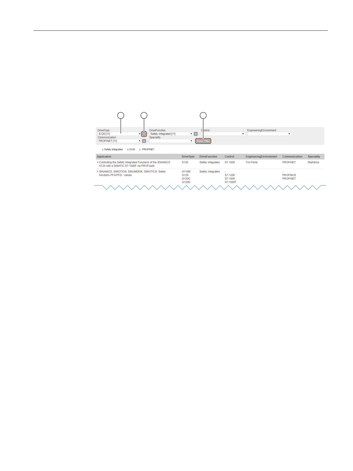
① Selectable options (e.g. S120): The number of available entries is displayed in the square
brackets.
② Reset individual filters
③ Reset all filters
Figure 7-19
Example: Filter settings
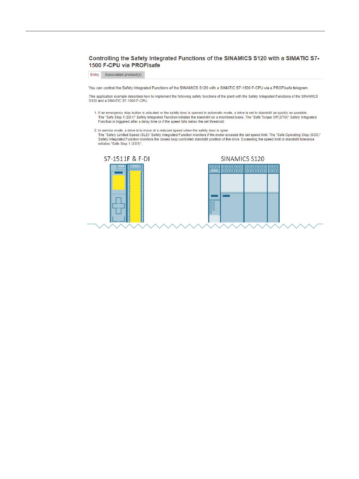
3. To view a tooltip on an entry, click the appropriate entry in the result list.
The required tooltip is then displayed in the Siemens Industry Online Support (SIOS).
Safety Integrated
Function Manual, 06/2020, 6SL3097-5AR00-0BP3
329
Commissioning
7.14 Application examples
Generally, you can download a detailed application description as PDF via the tooltip.
Safety Integrated
330
Function Manual, 06/2020, 6SL3097-5AR00-0BP3
Acceptance test
8
Note
Responsibilities
The machine manufacturer is responsible for carrying out and documenting the acceptance
test: In Chapter "Acceptance test with Startdrive (Page 343)" you will find a suggestion for how
to carry out and document the acceptance test for the individual safety functions.
You can find further information on the acceptance test here:
● General information about the acceptance test (Page 332)
● Contents and depth of the acceptance test (Page 335)
● Acceptance test with Startdrive (Page 343)
● Safety logbook (Page 349)
Safety Integrated
Function Manual, 06/2020, 6SL3097-5AR00-0BP3
331
Acceptance test
8.1 General information about the acceptance test
8.1
General information about the acceptance test
The EC Machinery Directive and DIN EN ISO 13849-1 stipulate:
● You must check safety-related functions and machine parts after commissioning.
→ Acceptance test.
For SINAMICS Safety Integrated Functions (SI Functions) this specifically means: The
acceptance test is used to check the functionality of the Safety Integrated monitoring and
stop functions used in the drive. The test objective is to verify proper implementation of the
defined safety functions and test mechanisms (measures for forced checking procedure
(test stop)) and to examine the response of specific monitoring functions to explicitly entered
values outside tolerance limits. The test must cover all drive-specific Safety Integrated
motion monitoring functions and global Safety Integrated functionality of Terminal Module
TM54F (if used).
Note
Purpose of the acceptance test
The measured values (e.g. distance, time) and the system behavior identified (e.g. initiation
of a specific stop) can be used for checking the plausibility of the configured safety functions.
The objective of an acceptance test is to identify potential configuration errors and/or to
document the correct function of the configuration. The measured values are typical values
(not worst case values). They represent the behavior of the machine at the time of
measurement. These measurements cannot be used to derive real values (e.g. maximum
values for over-travel distances).
● You must create an "acceptance report" showing the test results.
→ Documentation.
8.1.1
Requirements
The acceptance test requirements (configuration check) for electrical drive safety functions
emanate from DIN EN 61800-5-2, Section 7.1 Point f). The acceptance test "configuration
check" is cited in this standard.
● Description of the application including a picture
● Description of the safety-relevant components (including software versions) that are used
in the application
● List of the PDS(SR) [Power Drive System(Safety Related)] safety functions used
● Results of all tests of these safety functions, using the specified testing procedure
● List of all safety-relevant parameters and their values in the PDS(SR)
● Checksum, test date and confirmation by testing personnel
A complete acceptance test is required when first commissioning Safety Integrated
functionality on a machine. The acceptance tests must be carried out for each individual drive.
Safety-related function expansions, transfer of the commissioning settings to other series
machines, hardware changes, software upgrades or similar activities permit the acceptance
test to be performed with a reduced scope if necessary. A summary of conditions which
determine the necessary test scope or proposals in this context is provided below.
Safety Integrated
332
Function Manual, 06/2020, 6SL3097-5AR00-0BP3
Acceptance test
8.1 General information about the acceptance test
8.1.2
Requirements for the acceptance test
● The machine is properly wired.
● All safety equipment (such as protective door monitoring devices, light barriers, emergency
limit switches) are connected and ready for operation.
● Access rights to SI parameters must be protected by a password. This procedure must be
documented in the acceptance report - the password itself must not appear there.
● Commissioning of the open-loop and closed-loop control must be completed, as e.g. the
over-travel distance may otherwise change as a result of a changed dynamic response of
the drive control. These include, for example:
- Configuration of the setpoint channel
- Position control in the higher-level controller
- Drive control
8.1.3
Parts of the acceptance test
The acceptance test comprises 2 parts:
● Checking whether the safety functions in the converter are correctly set:
- Does the speed control handle the configured application cases in the machine?
- Do the set interface, times and monitoring functions match the configuration of the
machine?
● Checking whether the safety-relevant functions in the plant or machine function correctly.
This part of the acceptance test goes beyond the converter acceptance test:
- Are all safety equipment such as protective door monitoring devices, light barriers or
emergency-off switches connected and ready for operation?
- Does the higher-level control correctly respond to the safety-relevant feedback signals
of the converter?
- Do the converter settings match the configured safety-relevant function in the machine?
8.1.4
Documentation
The documentation consists of the following parts:
● Description of the safety-relevant components and functions of the machine or plant.
● Report of the acceptance test results.
● Report of the settings of the safety functions.
● The documentation must be signed by the person who carried out the acceptance test.
Safety Integrated
Function Manual, 06/2020, 6SL3097-5AR00-0BP3
333

Acceptance test
8.1 General information about the acceptance test
8.1.5
More information
Note
More information
● See the information in Chapters "Description of Safety Integrated functions (Page 75)" and
"Commissioning (Page 269)".
● In Chapter "Acceptance test with Startdrive (Page 343)" you will find a suggestion for how
to carry out and document the acceptance test for the individual safety functions.
● An acceptance report template in electronic format is available at your local Siemens sales
office.
Note
PFH values
The PFH values of the individual SINAMICS S120 safety components can be found at:
8.1.6
Acceptance test mode
Note on the acceptance test mode
The acceptance test mode can be activated for a definable period (p9558) by setting the
appropriate parameters (p9570). It tolerates specific limit violations during the acceptance test.
For instance, the setpoint speed limits are no longer active in the acceptance test mode. To
ensure that this state is not accidentally kept, the acceptance test mode is automatically exited
after the time set in p9558.
It is only worth activating acceptance test mode during the acceptance test of the SS2, SOS,
SDI, SLS and SLP functions. It has no effect on other functions.
Normally, SOS can be selected directly or via SS2. To be able to trigger violation of the SOS
standstill limits with acceptance test mode active (even in the "SS2 active" state), the setpoint
is enabled again by the acceptance test mode after deceleration and transition to SOS to allow
the motor to travel. When an SOS violation is acknowledged in the active acceptance test
mode, the current position is adopted as the new stop position so that an SOS violation is not
immediately identified again.
WARNING
Axis movement during the acceptance test
If a speed setpoint ≠ 0 is present, the active stop function SS2 is set, and the motor is at a
standstill (active SOS), the axis starts to move as soon as the acceptance test is activated. If
persons are in the danger zone, accidents causing death or severe injury can occur.
● Take suitable measures to ensure that nobody is in the danger zone during the acceptance
test.
Safety Integrated
334
Function Manual, 06/2020, 6SL3097-5AR00-0BP3
Acceptance test
8.2 Contents and depth of the acceptance test
8.2
Contents and depth of the acceptance test
8.2.1
Content of the complete acceptance test
A) Documentation
Documentation of the machine and of safety functions
● Machine description (with overview)
● Specification of the controller (if this exists)
● Function table:
- Active monitoring functions depending on the operating mode and the protective door
- Other sensors with protective functions
- The table is part or is the result of the configuring work.
● SI functions for each drive
● Information about safety equipment
B) Function test diagnostic/safety functions
Detailed function test and evaluation of SI functions used. For some functions, trace recordings
of individual parameters can be used.
The Acceptance test wizard (Page 343) in Startdrive supports you with these actions.
● Encoder parameterization test
- Required when using the Extended/Advanced Functions with encoder
- Only required at an encoder replacement
● Test of the SI function "Safe Torque Off" (STO)
- Required when used in Basic and/or Extended Functions
● Test of the SI function "Safe Stop 1" (SS1)
- Required when used in Basic and/or Extended Functions
- If the Extended Functions are used, individual parameters can be traced.
● Test of the SI function "Safe Brake Control" (SBC)
- Required when using Basic and/or Extended Functions
● Test of the SI function "Safe Stop 2" (SS2)
- For this purpose, individual parameters can be traced/recorded.
● Test of the SI function "Safe Operating Stop" (SOS)
- For this purpose, individual parameters can be traced/recorded.
Safety Integrated
Function Manual, 06/2020, 6SL3097-5AR00-0BP3
335
Acceptance test
8.2 Contents and depth of the acceptance test
● Test of the SI function "Safely-Limited Speed" (SLS)
- For this purpose, individual parameters can be traced/recorded.
● Test of the SI function "Safe Direction" (SDI)
- For this purpose, individual parameters can be traced/recorded.
● Test of the SI function "Safe Speed Monitor" (SSM)
- For this purpose, individual parameters can be traced/recorded.
● Test of the SI function "Safely-Limited Position" (SLP)
- For this purpose, individual parameters can be traced/recorded.
● Testing the SI function "Safe Cam" (SCA)
- For this purpose, individual parameters can be traced/recorded.
● Testing the SI function "Safely-Limited Acceleration" (SLA)
- For this purpose, individual parameters can be traced/recorded.
● Testing the "Safe Brake Test" (SBT) diagnostics function
- If the Extended Functions are used, individual parameters can be traced.
C) Function test of the forced checking procedure (test stop)
Test of the forced checking procedure (test stop) of the safety functions on each drive (for the
Basic and/or Extended/Advanced Functions) and the TM54F (if used).
● Test of the forced checking procedure (test stop) of the safety function on the drive
- If you are using Basic Functions, you need to activate and then deactivate STO once
again.
- If you are using Extended/Advanced Functions, you need to perform the forced checking
procedure (test stop).
● Forced checking procedure (test stop) of the TM54F (if available)
- Perform forced checking procedure (test stop) of the TM54F
● Forced checking procedure (test stop) of the CU310-2 (if available)
- Perform forced checking procedure (test stop) of the CU310-2
D) Conclusion of the report
Report of the commissioning status tested and countersignatures
● Inspection of SI parameters
● Logging of checksums (for each drive)
● Issuing of the safety password and documenting this process (do not specify the safety
password in the report!)
● RAM to ROM backup, upload of project data to Startdrive, and backup of the project
● Countersignature
Safety Integrated
336
Function Manual, 06/2020, 6SL3097-5AR00-0BP3
Acceptance test
8.2 Contents and depth of the acceptance test
8.2.2
Content of the partial acceptance test
A) Documentation
Documentation of the machine and of safety functions
1. Extending/changing the hardware data
2. Extending/changing the software data (specify version)
3. Extending/changing the function table:
- Active monitoring functions depending on the operating mode and the protective door
- Other sensors with protective functions
- The table is part or is the result of the configuring work
4. Extending/changing the SI functions per drive
5. Extending/changing the specifications of the safety equipment
B) Function test diagnostic/safety functions
Detailed function test and evaluation of SI functions used. For some functions, trace recordings
of individual parameters can be used.
The Acceptance test wizard (Page 343) in Startdrive supports you with these actions.
1. Test of the SI function "Safe Torque Off" (STO)
- Required when used in Basic and/or Extended Functions
- You do not need to prepare a trace recording for this test.
2. Test of the SI function "Safe Stop 1" (SS1)
- Required when used in Basic and/or Extended Functions
- If the Extended Functions are used, individual parameters can be traced.
3. Test of the SI function "Safe Brake Control" (SBC)
- Required when using Basic and/or Extended Functions
- You do not need to prepare a trace recording for this test.
4. Test of the SI function "Safe Stop 2" (SS2)
- For this purpose, individual parameters can be traced/recorded.
5. Test of the SI function "Safe Operating Stop" (SOS)
- For this purpose, individual parameters can be traced/recorded.
6. Test of the SI function "Safely-Limited Speed" (SLS)
- For this purpose, individual parameters can be traced/recorded.
7. Test of the SI function "Safe Direction" (SDI)
- For this purpose, individual parameters can be traced/recorded.
Safety Integrated
Function Manual, 06/2020, 6SL3097-5AR00-0BP3
337
Acceptance test
8.2 Contents and depth of the acceptance test
8. Test of the SI function "Safe Speed Monitor" (SSM)
- For this purpose, individual parameters can be traced/recorded.
9. Test of the SI function "Safely-Limited Position" (SLP)
- For this purpose, individual parameters can be traced/recorded.
10.Testing the SI function "Safe Cam" (SCA)
- For this purpose, individual parameters can be traced/recorded.
11.Testing the SI function "Safely-Limited Acceleration" (SLA)
- For this purpose, individual parameters can be traced/recorded.
12.Testing the "Safe Brake Test" (SBT) diagnostics function
- If the Extended Functions are used, individual parameters can be traced.
C) Function test of the forced checking procedure (test stop)
Test of the forced checking procedure (test stop) of the safety functions on each drive (for the
Basic and/or Extended/Advanced Functions) and the TM54F (if used).
1. Test of the forced checking procedure (test stop) of the safety function on the drive
- If you are using Basic Functions, you need to activate and then deactivate STO once
again.
- If you are using Extended/Advanced Functions, you need to perform the forced checking
procedure (test stop).
2. Forced checking procedure (test stop) of the TM54F (if available)
- Perform forced checking procedure (test stop) of the TM54F
3. Forced checking procedure (test stop) of the CU310-2 (if available)
- Perform forced checking procedure (test stop) of the CU310-2
Safety Integrated
338
Function Manual, 06/2020, 6SL3097-5AR00-0BP3

Acceptance test
8.2 Contents and depth of the acceptance test
D) Function test of actual value acquisition
1. General testing of actual value acquisition
- After exchanging the component, initial activation and brief operation in both directions.
WARNING
Axis movement during the acceptance test
The operation causes the machine to move.
● Take suitable measures to ensure that nobody is in the danger zone during the
acceptance test.
2. Test of failsafe actual value acquisition
- Only necessary when using Extended Advanced Functions
- If the motion monitoring functions are activated (e.g. SLS or SSM with hysteresis), briefly
operate the drive in both directions.
3. Encoder parameterization test
- Required when using the Extended/Advanced Functions with encoder
- Only required at an encoder replacement
- You do not need to prepare a trace recording for this test.
E) Conclusion of the report
Report of the commissioning status tested and countersignatures
1. Extension of checksums (for each drive)
2. Countersignature
8.2.3
Test scope for specific measures
Scope of partial acceptance tests for specific measures
The measures and points specified in the table refer to the information given in Section Content
of the partial acceptance test (Page 337).
Table 8-1
Scope of partial acceptance tests for specific measures
Measure
A) Documentation
B) Functional testing
C) Functional testing of
D) Functional test-
E) Conclu-
of safety functions
the forced checking
ing of actual value
sion of the re-
procedure (test stop)
acquisition
port
Replacement of
No
No
No
Yes
Yes
the encoder sys-
tem
Replacement of
Yes, Points 1 and 2
No
No
Yes
Yes
an SMC/SME
Safety Integrated
Function Manual, 06/2020, 6SL3097-5AR00-0BP3
339

Acceptance test
8.2 Contents and depth of the acceptance test
Measure
A) Documentation
B) Functional testing
C) Functional testing of
D) Functional test-
E) Conclu-
of safety functions
the forced checking
ing of actual value
sion of the re-
procedure (test stop)
acquisition
port
Replacement of
Yes, Points 1 and 2
No
No
Yes
Yes
a motor with
DRIVE-CLiQ
Replacement of
Yes, Points 1 and 2
Yes, Points 1 or 2 and
Yes, only Point 1
Yes, only Point 1
Yes
the following
3
hardware: Con-
trol Unit, Motor
Module, Power
Module, or Safe
Brake Relay
Replacement of
Yes, Points 1 and 2
Yes, but only testing
Yes
Yes, only Point 1
Yes
the TM54F
of the selection of the
safety functions
Firmware modifi-
Yes, only Point 2
Yes, if new safety
Yes
Yes, only Point 1
Yes
cation1)(CU /
functions are to be
power unit / Sen-
used
sor Modules)
Change to a sin-
Yes, Points 4 and
Yes, test the appropri-
No
Yes
Yes
gle parameter of
5.
ate function
a safety function
(e.g. SLS limit)
Transfer of
Yes
Yes, but only testing
Yes
Yes
Yes
project data to
of the selection of the
other machines
safety functions
(series commis-
sioning)
Other firmware
Yes, only Point 2
Yes, if new safety
Yes
Yes, only Point 1
Yes
version1) on Si-
functions are to be
motion D
used
1)
Upgrading or downgrading
8.2.4
Relevant checksums for the acceptance
Checksums of the safety functions
The following checksums are available for every drive with activated safety functions.
Safety function/
Checksum
Reason for changing the checksum
parameters
Basic Functions
p9799
Reference checksum (channel 1)
Changing the safety parameters of basic functions
p9899
Reference checksum (channel 2)
Extended/Advanced Functions
p9799
Reference checksum (channel 1)
Changing a safety parameter of the Extended/ Ad-
vanced Functions
p9899
Reference checksum (channel 2)
Safety Integrated
340
Function Manual, 06/2020, 6SL3097-5AR00-0BP3

Acceptance test
8.2 Contents and depth of the acceptance test
Safety function/
Checksum
Reason for changing the checksum
parameters
p9729[0]
Reference checksum SI parameters for mo-
Changing a safety parameter of the Extended/ Ad-
tion monitoring (channel 1)
vanced Functions, which does not refer to encoder da-
ta.
p9729[1]
Reference checksum SI parameters for ac-
Changing encoder parameters (e.g. encoder pulse
tual values (channel 1)
number, fine resolution, …) or mechanical settings
(e.g. gear unit, spindle pitch, …)
p9729[2]
Reference checksum SI parameters for hard-
As soon as a Sensor Module evaluated by safety inte-
ware (channel 1)
grated is replaced
p9399[0]
Reference checksum SI parameters for mo-
Changing a safety parameter of the Extended/ Ad-
tion monitoring (channel 2)
vanced Functions
p9399[1]
Reference checksum SI parameters with
Replacing safety-relevant hardware
hardware reference (channel 2)
TM54F
p10005[0]
Reference checksum, hardware-independ-
Changing a TM54F safety parameter
ent TM54F parameters (available for master
and slave modules)
p10005[1]
Reference checksum, hardware-dependent
Replacing a Motor Module which is controlled via the
TM54F parameters
TM54F
All safety changes (functional or related to the hardware) are documented in the safety logbook
of the Control Unit. As soon as a safety parameter is changed, then the checksum in the Control
Unit also changes. As a consequence, it is sufficient to document the functional checksum of
the safety logbook (r9781[0]) and the associated time stamp (r9782[0]).
Note
For the functional checksum, it must be guaranteed that the components to be replaced are
replaced by identical components (the same MLFB).
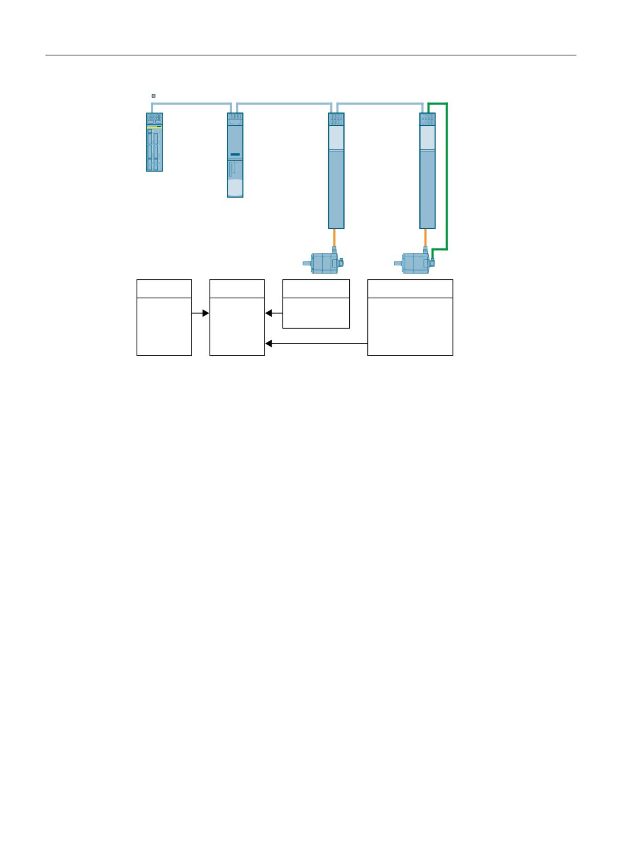
The following diagram shows the functional reference checksums of the SINAMICS
components for the safety logbook of the Control Unit.
Safety Integrated
Function Manual, 06/2020, 6SL3097-5AR00-0BP3
341
Acceptance test
8.2 Contents and depth of the acceptance test
'5,9( &/L4
70
)
&RQWURO 8QLW
0RWRU
0RWRU
0RGXOH
0RGXOH
&KHFNVXPV
70
)
&RQWURO 8QLW
%DVLF )XQFWLRQV
([WHQGHG )XQFWLRQV
0DVWHU
U
> @
S
S
S
> @
U
> @
S
S
S
> @
6ODYH
6DIHW\
S
> @
S
> @
ORJERRN
S
> @
Figure 8-1
Parameters for the functional reference checksums of SINAMICS components
Safety Integrated
342
Function Manual, 06/2020, 6SL3097-5AR00-0BP3

Acceptance test
8.3 Acceptance test with Startdrive
8.3
Acceptance test with Startdrive
8.3.1
Notes
Note
Conditions for the acceptance test
As far as possible, the acceptance tests are to be carried out at the maximum possible machine
speed and acceleration rates to determine the maximum braking distances and braking times
that can be expected.
Note
Acceptance test for Basic and Extended Functions
In the function selection, the Safety Integrated acceptance test offers you the testable functions
for selection, depending on the device type and its settings (Basic or Extended Functions,
control via PROFIsafe or terminals).
Note
Trace recordings
The trace recordings for the Extended Functions allow the analysis of the machine behavior
during the test execution. Here you use the signal characteristics to check whether the machine
behavior meets your expectations. The recorded signals allow, for example, the delay times
and over-travel distances to be evaluated.
Note
Non-critical alarms
When evaluating the alarm buffer you can tolerate the following alarms:
● A01697 SI Motion: Motion monitoring test required
● A35014 TM54F: Test stop required
These alarms occur after every system startup and can be evaluated as non-critical.
● A01699 SI CU: Shutdown path test required
This alarm occurs after the time in p9659 has expired.
You do not need to include these alarms in the acceptance report.
Note
No acceptance test with alarm A01796
If the alarm A01796 is active, the pulses are safely canceled, and an acceptance test is not
possible.
Safety Integrated
Function Manual, 06/2020, 6SL3097-5AR00-0BP3
343
Acceptance test
8.3 Acceptance test with Startdrive
8.3.2
Preparing the acceptance test
Establishing an overview of all drives
1. Click "Acceptance test" in the project tree.
2. Select the "Overview" screen form in the secondary navigation.
3. Click "Determine" to determine all drives with Safety Integrated Functions in your Startdrive
project.
4. The overview window lists all available drives with Safety Integrated Functions as well as
their respective test status.
Color coding of the test status:
- Gray: Safety Integrated Functions have been parameterized, but the acceptance test
has not yet been performed
- Red: Acceptance test failed
- Blue: Acceptance test in the initial state
- Green: Acceptance test successful
5. Click "Output" to generate an overview as a table in "xlsx" format. You can open this table
in Microsoft Excel and other spreadsheet programs (e.g. LibreOffice).
You can use the overview to track and/or document your work progress, especially for
projects with several drives.
Preparing the acceptance test
1. The drives to be tested have been fully parameterized and commissioned. Subsequent
changes require performing a new acceptance test.
2. Click "Acceptance test" in the project tree.
Those Safety Integrated Functions available in the drive unit are offered for selection.
Whereby, the selection considers whether Basic Functions, Extended Functions or
Advanced Functions were selected as well as the activation type (PROFIsafe or onboard
terminals).
3. Select in the secondary navigation for the desired drive unit all Safety Integrated Functions
to be tested.
The active functions are preselected automatically. This preselection can be changed and
functions selected or deselected.
4. Click "Accept" to specify the function selection for the Safety Integrated acceptance test.
Entries for the functions to be tested are displayed in the secondary navigation. Navigate
with these settings to the individual tests.
5. Establish an online connection to the drive unit to be tested.
Resetting test results
1. Click the "Reset test results" button to delete all the results of the tests previously performed
for this drive.
This restores the initial state from which you can perform the acceptance tests again.
Safety Integrated
344
Function Manual, 06/2020, 6SL3097-5AR00-0BP3
Acceptance test
8.3 Acceptance test with Startdrive
8.3.3
Performing the acceptance test (example)
Description
After accepting the function selection in the "Preparing the acceptance test (Page 344)" step,
the functions to be tested are displayed in the secondary navigation.
You can now perform the tests from top to bottom or in any required sequence.
The status of the individual tests is represented as follows:
● Blue: The test is initial and has not yet been tested.
● Green: The test was performed successfully.
● Red: The test was aborted with error. The test can be repeated by reselecting the function.
Structure of the acceptance test wizards
The listed wizards have the same structure for every acceptance test.
The upper area contains the workflow that represents the individual test steps and their status.
The states have the following meaning:
● Blue: Active test step.
● Green: Test step completed.
The instructions for the test steps are displayed in the area below the workflow. The test steps
must be performed by the user. After performing the instructions, click "Next" to advance to the
next step. At the end, the test is completed by clicking "Finish". The status of this test is then
updated in the secondary navigation.
The operator controls for the test steps are located in the lower area. This includes, for example,
the control panel for traversing the axis to be tested.
Starting and performing the acceptance test
1. Click one of the functions to be tested (SS1 in this case).
The wizard is started in the working area.
2. Enter a test designation. This designation also appears later in the acceptance report.
3. You can change the trace settings for this test or use the preassignment. The
preassignment is adequate for most applications.
A change permits adaptation to the mechanical conditions of the machine, e.g. when the
axis mechanical system exhibits a very high moment of inertia so that longer ramp-up times
for accelerating and braking are required.
4. Observe the safety information and notes on the start screen form of the acceptance test.
5. Once you have performed all preparations, click "Start test".
The wizard for the selected test opens.
Safety Integrated
Function Manual, 06/2020, 6SL3097-5AR00-0BP3
345
Acceptance test
8.3 Acceptance test with Startdrive
6. In the first step, the drive must be moved so that an emergency stop can be initiated.
Select in the "Move drive via" drop-down list whether the drive should be moved via the
control panel or via the user program of a higher-level control.
- Control panel:
If the drive is moved via the control panel, it is displayed in this screen form.
Activate the master control, enter a setpoint and start the motor in the desired direction
of rotation.
Click "Next" to advance to the next step.
- User program:
Start moving when the drive is moved from the user program.
Click "Next" to advance to the next step once the motor starts to turn.
7. Initiate emergency stop (SS1) on the selected drive. Click "Next" when the LED indicates
that SS1 is active.
The motor brakes on the OFF3 braking ramp. The transition to STO is made based on the
parameter assignment (e.g. after expiration of the delay time or when the shut-down speed
is undershot). If a brake parameterized via SBC is present, it is closed after transition to STO.
8. Return the master control when the drive is stationary. Click "Next".
9. The previous workflow is recorded and represented as trace.
Check the chronological and content workflow of the test based on the signal recording. In
this test, STO may be initiated only when the motor has almost become stationary.
Click "Next" provided the test workflow meets your expectations.
10.Alternatively: Cancel the test by clicking "Cancel" if the workflow does not meet your
expectations.
In this case, check the correctness of all input conditions and repeat the test, if necessary.
Sample scenario: STO is initiated, even though the motor speed is still high. In this case, a
possible cause could be incorrect parameterization, e.g. an insufficiently short delay time
from SS1 to STO or an excessively high shut-down speed.
11.Deselect SS1 and click "Next".
The test was performed successfully.
12.Click "Finish" to exit the wizard.
Result
The test status in the secondary navigation is updated.
Execute the wizards of all further functions similarly through the tests.
8.3.4
Completing the acceptance test with report
Description
The acceptance report can be created at any time, for example, even when individual tests
have not yet been performed or completed with faults. This allows the intermediate states also
to be documented.
Safety Integrated
346
Function Manual, 06/2020, 6SL3097-5AR00-0BP3

Acceptance test
8.3 Acceptance test with Startdrive
The actual final acceptance report, however, makes sense only when all tests have been
performed successfully.
Requirement
● All tests have been successfully completed. The individual tests are all identified positively
with a green tick.
Creating an acceptance report
1. The overview under "Create report" lists all drives and their current test status.
2. In the "Completion" screen form, select the drives for which you would like to create the
report.
You can select any number of drives, regardless of their test status.
The drive instances to which the results were transferred are also displayed in the list as
drop-down sub-entries. These drive instances are always included in the acceptance report
with the selection of the respective main drive.
3. Click on the "Create" button.
The "Save as" dialog opens.
4. When you select a drive, its drive name is preset as a suggestion for the file name for the
acceptance test as standard.
When you select multiple drives, a dialog for selecting the directory for storing the report
opens. For each drive selected, a report is saved with the name of the drive.
Optional: Creating a function table
You can use the function table to create a user-defined overview that is documented in the
acceptance report in addition to the results of acceptance test.
The overview is structured as follows:
Column
Explanation
Operating mode
Select one of the specified operating modes from the drop-down list to map the
desired scenario.
Description
Enter an explanatory comment for the selected operating mode.
Protective device
Select the protective mechanism to be used in the applicable scenario from the
drop-down list.
Version
Enter an explanatory comment on the protective device being used.
Axis
Select the respective drive axis from the drop-down list.
Monitoring
Select the Safety Integrated Function being used from the drop-down list.
Result
The acceptance report is created as a table in "xlsx" format and can thus be opened in Microsoft
Excel and other spreadsheet programs (e.g. LibreOffice).
Safety Integrated
Function Manual, 06/2020, 6SL3097-5AR00-0BP3
347
Acceptance test
8.3 Acceptance test with Startdrive
The report comprises several individual tables. These include:
● Cover page: Introduction with the machine description
● Drive_x - overview: Documentation of the parameters and traces for this drive
● Drive_x - function test: Documentation of all test data for this drive
Test status color coding:
- Red: Failed
- Yellow: Not tested
- Green: Test successful
● Completion: Summary and signatures
Note
Correct display of the acceptance report
How the acceptance report is displayed is dependent on the Windows settings and
spreadsheet program used to call up the file.
● Microsoft Excel
The acceptance report is displayed correctly in Microsoft Excel when the following is
configured in the Windows display settings:
Control Panel > Appearance and Personalization > Display > Make text and other items
larger or smaller > Option "Smaller - 100%"
● LibreOffice
The acceptance report is displayed independently of the Windows settings and is thus
always correct.
8.3.5
Transferring acceptance test results
To simplify further acceptance tests, you can transfer the results of successful tests to drives
with the same functionality. The Safety Integrated acceptance test wizard lists the suitable
drives.
1. Open the "Result transfer" screen form for a drive for which you have successfully
completed the acceptance test.
2. Click on the "Determine" button to determine suitable drives.
After initial determination, the button changes to "Refresh".
3. Select the drives to which you want to transfer the results.
The selected drives become instances of the tested drive.
4. Click the "Accept" button.
The transfer status is displayed in the screen form.
Safety Integrated
348
Function Manual, 06/2020, 6SL3097-5AR00-0BP3
Acceptance test
8.4 Safety logbook
8.4
Safety logbook
The "Safety Logbook" function is used to detect changes to safety parameters that affect the
associated CRC sums. CRCs are only generated when p9601 (SI enable, functions integrated
in the drive CU/Motor Module) is > 0.
Data changes are detected when the CRCs of the SI parameters change. Each SI parameter
change that is to become active requires the reference CRC to be changed so that the drive can
be operated without SI fault messages. In addition to functional safety changes, safety changes
as a result of hardware being replaced can be detected when the CRC has changed.
The following changes are recorded by the safety logbook:
● Functional changes are recorded in the checksum r9781[0]:
- Functional CRCs of the motion monitoring functions (p9729[0..1]), axis specific
(Extended and Advanced Functions)
- Functional cyclic redundancy checks of the basic safety functions integrated in the drive
(p9799, SI setpoint checksum SI parameters CU), for each axis.
- Functional CRCs of the TM54F (p10005[0]), global (Basic, Extended and Advanced
Functions)
- Enabling functions integrated in the drive (p9601), axis specific (Basic, Extended and
Advanced Functions)
● Hardware-dependent changes are recorded in the checksum r9781[1]:
- Hardware-dependent CRC of the motion monitoring functions (p9729[2]), axis specific
(Extended and Advanced Functions)
- Functional CRCs of the TM54F (p10005[1]), global (Basic, Extended and Advanced
Functions)
Safety Integrated
Function Manual, 06/2020, 6SL3097-5AR00-0BP3
349
Acceptance test
8.4 Safety logbook
Safety Integrated
350
Function Manual, 06/2020, 6SL3097-5AR00-0BP3

System features
9
9.1
Latest information
Important note for maintaining the operational safety of your system:
NOTICE
Danger to operational safety due to unwanted motion
Systems with safety-related characteristics are subject to special operational safety
requirements on the part of the operating company. If information on a lack of product safety
becomes known in the course of observing a product, this information is declared in various
ways. For this reason, we publish a special newsletter containing information on product
developments and features that are (or could be) relevant when operating safety-related
systems.
● You should subscribe to and carefully read the corresponding newsletter in order to obtain
the latest information and to allow you to modify your equipment accordingly.
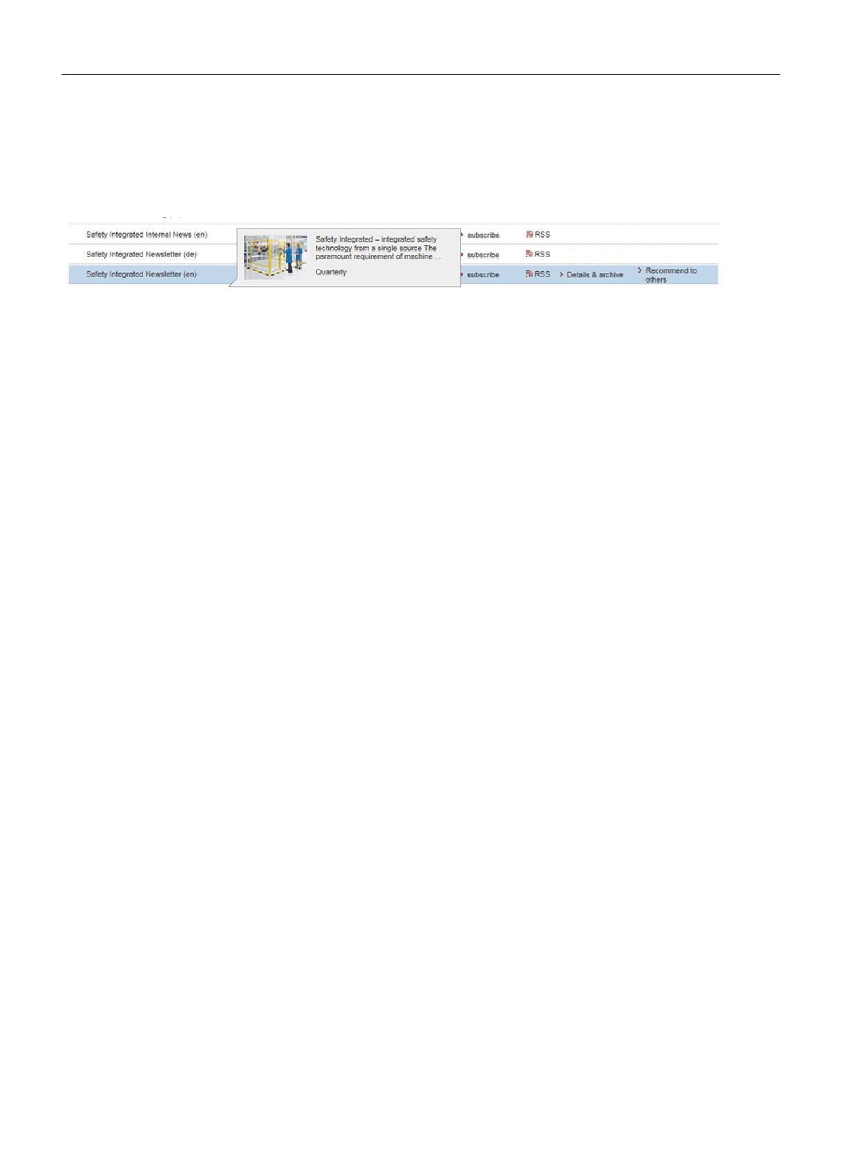
To subscribe to the newsletter, please proceed as follows:
1. Go to the following Siemens internet site in your browser:
2. Select the desired language for the Web page.
Note
Newsletter
You have to register and log in if you want to subscribe to any newsletters. You will be led
automatically through the registration process.
3. Click on "Login / registration".
4. Login with your access data. If you do not yet have a login and password, select "Yes, I
would like to register now".
You can subscribe to the individual newsletters in the following window.
5. Under the "All newsletters" heading on this page, you can see which newsletter is currently
available.
Safety Integrated
Function Manual, 06/2020, 6SL3097-5AR00-0BP3
351
System features
9.1 Latest information
6. Open the topic "Products and solutions".
You will now be shown which newsletter is available for this particular subject area or topic.
You can subscribe to the appropriate newsletter by clicking on the "Subscribe" entry. If you
require more detailed information on the newsletters, then please use the supplementary
function on the website.
7. At the very least, register for the newsletters for the following product areas:
- Safety Integrated Newsletter
Safety Integrated
352
Function Manual, 06/2020, 6SL3097-5AR00-0BP3
System features
9.2 Certification
9.2
Certification
The safety functions of the SINAMICS S drive system meet the following requirements:
● Category 3 to DIN EN ISO 13849-1
● Performance level (PL) d according to DIN EN ISO 13849-1
● Safety integrity level 2 (SIL 2) according to IEC 61508 and EN 61800-5-2
In addition, most of the safety functions of the SINAMICS S have been certified by independent
institutes. An up-to-date list of certified components is available on request from your local
Siemens office.
Safety Integrated
Function Manual, 06/2020, 6SL3097-5AR00-0BP3
353
System features
9.3 Probability of failure of the safety functions (PFH value)
9.3
Probability of failure of the safety functions (PFH value)
The probability of failure of safety functions must be specified in the form of a PFH value
(Probability of Failure per Hour) according to IEC 61508, IEC 62061 and DIN EN ISO 13849-1.
The PFH value of a safety function depends on the safety concept of the drive unit and its
hardware configuration, as well as on the PFH values of other components used for this safety
function.
Corresponding PFH values are provided for the SINAMICS S120 drive system, depending on
the hardware configuration (number of drives, control type, number of encoders used). The
various integrated safety functions are not differentiated.
● The PFH values of the individual SINAMICS S120 safety components can be found at:
● The PFH values of all safety components from Siemens are available in the "Safety
Evaluation Tool"; see:
Safety Evaluation Tool (http://www.industry.siemens.com/topics/global/en/safety-
integrated/machine-safety/safety-evaluation-tool/Pages/default.aspx)
Safety Integrated
354
Function Manual, 06/2020, 6SL3097-5AR00-0BP3
System features
9.4 Response times
9.4
Response times
The Safety Integrated Basic Functions are executed in the monitoring cycle (p9780).
PROFIsafe telegrams are evaluated in the PROFIsafe scan cycle, which corresponds to twice
the monitoring clock cycle (PROFIsafe scan cycle = 2 · r9780).
Note
Actual value of the monitoring cycle (r9780)
You can only see the actual value of the monitoring cycle (r9780) if you are connected online
with the drive. However, you can use the following values to roughly calculate the response
times:
● If P0115[0] = 31.25 µs or 62.5 µs or 125 µs, then r9780 = 4 ms.
● If p0115[0] = 250 µs, then r9780 = 8 ms.
● If p0115[0] = 400 µs or 500 µs, then r9780 = 16 ms.
Note for understanding the tables
The drive system is the component that provides the safety functions. The designation "fault-
free drive system" means that the component that provides the safety functions does not have
a defect itself:
● Worst case for a fault-free drive system
For faults outside the drive system (e.g. faulty setpoint input from a control system, limit
value violations as a result of the behavior of the motor, closed-loop control, load, etc.), the
"Worst case for a fault-free drive system" response time is guaranteed.
● Worst case when a fault exists
For a single fault within the drive system (e.g. a defect in a switch-off signal path of the power
unit, in an encoder actual value measurement, in a microprocessor (Control Unit or Motor
Module) etc.), the "Worst case when a fault exists" response time is guaranteed.
Safety Integrated
Function Manual, 06/2020, 6SL3097-5AR00-0BP3
355

System features
9.4 Response times
9.4.1
STO and SBC via terminals of the Power Modules Blocksize
The following table lists the response times from the control via terminals STO_A, STO_B of the
Power Modules Blocksize until the response actually occurs.
Table 9-1
Response times for control via terminals on the Control Unit and the Motor Module.
Function
Worst case for
Drive system has no fault
A fault is present
STO
Terminals STO_A, STO_B of the Power
20 ms
-
Modules PM240-2 or PM240P-2 (HW
STO)
SBC
Terminals STO_A, STO_B of the Power
24 ms
-
Modules PM240-2 or PM240P-2
Output time of the HW STO (r1838)
-
feedback signals via a digital output
20 ms + 2 · p0799[0]
Safety Integrated
356
Function Manual, 06/2020, 6SL3097-5AR00-0BP3

System features
9.4 Response times
9.4.2
Control of Basic Functions via terminals on the Control Unit and Motor Module
(CU310-2 and CU320-2)
The following table lists the response times from the control via terminals until the response
actually occurs.
Table 9-2
Response times for control via terminals on the Control Unit and the Motor Module.
Function
Worst case for
Drive system has no fault
A fault is present
STO
2 · r9780 + t_E1)
3 · r9780 + t_E1)
SS1/SS1E (time-controlled)
Selection until STO is initiated
2 · r9780 + p9652 + t_E1)
3 · r9780 + p9652 + t_E1)
SS1/SS1E (time-controlled)
Selection until SBC is initiated
4 · r9780 + p9652 + t_E1)
8 · r9780 + p9652 + t_E1)
SS1 (time-controlled)
Selection until braking is initiated
3 · r9780 + 2 ms + t_E1)
4 · r9780 + 2 ms + t_E1)
SBC
4 · r9780 + t_E1)
8 · r9780 + t_E1)
1)
The following applies for t_E (debounce time of the digital input being used):
p9651 = 0
t_E1) = 2 · p0799 (default = 4 ms)
p9651 ≠ 0
t_E1) = p9651 + p0799 + 1 ms
1)
The minimum time for t_E is t_E_min = 2 ms.
Safety Integrated
Function Manual, 06/2020, 6SL3097-5AR00-0BP3
357

System features
9.4 Response times
9.4.3
Control of Basic Functions via PROFIsafe (CU310-2 and CU320-2)
The following table lists the response times from receiving the PROFIsafe telegram at the
Control Unit up to initiating the particular response.
Note
Internal SINAMICS response times
The specified response times are internal SINAMICS response times. Program run times in the
F-host and the transmission time via PROFIBUS or PROFINET are not taken into account.
When calculating the response times between the F-CPU and the converter, you must take into
account that faults in the communication can result in a safety function only being selected after
the PROFIsafe monitoring time (F_WD_Time) has expired. The PROFIsafe monitoring time
(F_WD_Time) must also be included in the calculation when an error occurs.
Table 9-3
Response times when controlling via PROFIsafe
Function
Worst case for
Drive system has no fault
A fault is present
STO
5 · r9780 + t_K2)
5 · r9780 + t_K2)
SS1/SS1E (time controlled)
Selection until STO is initiated
5 · r9780 + p9652 + t_K2)
5 · r978 + p9652 + t_K2)
SS1/SS1E (time controlled)
Selection until SBC is initiated
6 · r9780 + p9652 + t_K2)
10 · r9780 + p9652 + t_K2)
SS1 (time controlled)
Selection until braking is initiated
5 · r9780 + 2 ms + t_K2)
5 · r9780 + 2 ms + t_K2)
SBC
6 · r9780 + t_K2)
10 · r9780 + t_K2)
2)
t_K is the time for internal communication within the SINAMICS module. t_K can be determined as follows:
Isochronous communication
t_K = To (for To, see parameter r2064[4])
Non-isochronous communication
t_K = 4 ms
Applies to modules on which p2048 (for communication via IF1) or p8848 (for
communication via IF2) do not exist.
t_K = value from p2048 or p8848
Applies to modules on which p2048 (for communication via IF1) or p8848 (for
communication via IF2) exist.
Safety Integrated
358
Function Manual, 06/2020, 6SL3097-5AR00-0BP3

System features
9.4 Response times
9.4.4
Control of Basic Functions via TM54F
The following table lists the response times from the control via TM54F until the response
actually occurs.
Table 9-4
Response times for control via TM54F
Function
Worst case for
Drive system has no fault
A fault is present
STO
3 · r9780 + p10017 + 2 ms
3 · r9780 + p10017 + 2 ms
SS1/SS1E (time-controlled)
3 · r9780 + p9652 + p10017 + 2 ms
3 · r9780 + p9652 + p10017 + 2 ms
Selection until STO is initiated
SS1/SS1E (time-controlled)
4 · r9780 + p9652 + p10017 + 2 ms
8 · r9780 + p9652 + p10017 + 2 ms
Selection until SBC is initiated
SS1 (time-controlled)
3 · r9780 + p10017 + 4 ms
3 · r9780 + p10017 + 4 ms
Selection until braking is initiated
SBC
4 · r9780 + p10017 + 2 ms
8 · r9780 + p10017 + 2 ms
Safety Integrated
Function Manual, 06/2020, 6SL3097-5AR00-0BP3
359

System features
9.4 Response times
9.4.5
Control of Extended Functions with encoder via PROFIsafe (CU310-2 and
CU320-2)
The following table lists the response times1)2) from receiving the PROFIsafe telegram at the
Control Unit up to initiating the particular response.
Table 9-5
Response times when controlling via PROFIsafe
Function
Worst case for
Drive system has no fault
A fault is present
STO
5 · p95008) + r9780 + t_K6)
5 · p95008) + 2 · r9780 + t_K6)
SS1 (time controlled), SS1E, SS2E: Time from select-
ing up to starting the safe timer
SS1 (acceleration controlled), SS2: Time from select-
ing up to initiating braking
SOS: Time from selecting up to starting standstill mon-
itoring
5 · p95008) + 2 ms + t_K6)
5 · p95008) + 2 ms + t_K6)
SBC
5 · p95008) + 2 · r9780 + t_K6)
5 · p95008) + 6 · r9780 + t_K6)
SBR or SAM (limit value violation until STO active)
2 · p9500 + r9780
2.5 · p9500 + r9780 + t_ACT5)
SOS standstill tolerance window violated
1.5 · p9500 + 2 ms
3 · p9500 + 2 ms + t_ACT5)
SLS speed limit violated 3)
2 · p9500 + 2 ms
3.5 · p9500 + 2 ms + t_ACT5)
SSM4)
4 · p9500
4.5 · p9500 + t_ACT5)
SDI (limit value violation until braking is initiated)
1.5 · p9500 + 2 ms
3 · p9500 + 2 ms + t_ACT5)
SLA: Selection or deselection
5 · p95008) + t_K
5 · p95008) + t_K
SLA: Limit value violation
3 · p9500 + 2 ms
4 · p9500 + 2 ms + t_act
1)
The specified response times are valid for Extended Functions with and without selection.
2)
The specified response times involve internal SINAMICS response times. Program run times in the F-host and the
transmission time via PROFIBUS or PROFINET are not taken into account. When calculating the response times between
the F-CPU and the converter, you must take into account that faults in the communication can result in a safety function only
being selected after the PROFIsafe monitoring time (F_WD_Time) has expired. The PROFIsafe monitoring time
(F_WD_Time) must also be included in the calculation when an error occurs.
3)
SLS: Specification of the response time required to initiate a braking response in the drive - or for the output of the "SOS
selected" message to the motion control system.
4)
SSM: The data corresponds to the times between the limit value being undershot up to sending the information via
PROFIsafe.
5)
t_ACT:
For p9511 ≠ 0
t_ACT = p9511
For p9511 = 0
If an isochronous PROFIBUS master is available:
t_ACT = PROFIBUS cycle
Otherwise:
t_ACT = 1 ms
6)
t_K is the time for internal communication within the SINAMICS module; t_K can be determined as follows:
Safety Integrated
360
Function Manual, 06/2020, 6SL3097-5AR00-0BP3
System features
9.4 Response times
For isochronous communication
t_K = To (for To, see parameter r2064[4])
For non-isochronous
t_K = 4 ms
communication
(for modules, on which p2048 or p88487) does not exist)
t_K = value from p2048 or p88487)
(for modules on which p2048 or p88487) exists)
7)
p2048 applies to communication via IF1, p8848 to communication via IF2.
8)
This component will be reduced from 5 · p9500 to 3 · p9500 if an isochronous PROFIsafe telegram is used with optimally
timed execution on the F-CPU.
Safety Integrated
Function Manual, 06/2020, 6SL3097-5AR00-0BP3
361

System features
9.4 Response times
9.4.6
Control of Extended Functions with encoder via TM54F (CU310-2 and CU320-2)
The table below shows the response times1) from the occurrence of a signal at the terminals
until the response is initiated.
Table 9-6
Response times for control via TM54F
Function
Worst case for
Drive system has no fault
A fault is present
STO
3,5 · p9500 + r9780 + p100174) +
4 · p9500 + 2 · r9780 + p100174) +
1 ms
1 ms
SS1 (time and acceleration controlled),
SS1E (tme controlled),
SS2 selection until braking is initiated
3,5 · p9500 + p100174) + 3 ms
4 · p9500 + p100174) + 3 ms
SBC
3,5 · p9500 + 2 · r9780 + p100174) +
4 · p9500 + 6 · r9780 + p100174) +
1 ms
1 ms
SBR or SAM
(limit value violation until STO active)
2 · p9500 + r9780
2,5 · p9500 + r9780 + t_IST5)
SOS standstill tolerance window violated
1,5 · p9500 + 2 ms
3 · p9500 + 2 ms + t_IST5)
SLS speed limit violated 2)
2 · p9500 + 2 ms
3,5 · p9500 + 2 ms + t_IST5)
SSM3)
3 · p9500
3,5 · p9500 + t_IST5)
SDI
(limit value violation until braking is initiated)
1,5 · p9500 + 2 ms
3 · p9500 + 2 ms + t_IST5)
1)
The specified response times are valid for Extended Functions with and without selection!
2)
SLS: Specification of the response time required to initiate a braking response in the drive - or for the output of the "SOS
selected" message to the motion control system.
3)
SSM: The data corresponds to the times between the limit value being fallen below up to output of the information at the F-
DO.
4)
For CU310-2, use the parameter p10017 of the drive object "TM54F_xx" to calculate the response time, not that of the
control unit.
5)
For t_ACT, the following applies:
For p9511 ≠ 0
t_ACT = p9511
For p9511 = 0
If an isochronous PROFIBUS master is available:
t_ACT = PROFIBUS cycle
Otherwise:
t_ACT = 1 ms
Safety Integrated
362
Function Manual, 06/2020, 6SL3097-5AR00-0BP3

System features
9.4 Response times
9.4.7
Control of Extended Functions with encoder via terminals (only CU310-2)
The table below shows the response times1) from the occurrence of a signal at the terminals
until the response is initiated.
Table 9-7
Response times when controlling the Extended Functions with encoder via safe onboard terminals (only
CU310-2)
Function
Worst case for
Drive system has no fault
A fault is present
STO
3,5 · p9500 + r9780 + t_E5)
4 · p9500 + 2 · r9780 + t_E5)
SS1 (time and acceleration controlled),
SS1E (tme controlled),
SS2 selection until braking is initiated
3,5 · p9500 + 2 ms + t_E5)
4 · p9500 + 2 ms + t_E5)
SBC
3,5 · p9500 + 2 · r9780 + t_E5)
4 · p9500 + 9 · r9780 + t_E5)
SBR or SAM (limit value violation until STO active)
2 · p9500 + r9780
2,5 · p9500 + r9780 + t_IST4)
SOS standstill tolerance window violated
1,5 · p9500 + 2 ms
3 · p9500 + 2 ms + t_IST4)
SLS speed limit violated 2)
2 · p9500 + 2 ms
3,5 · p9500 + 2 ms + t_IST4)
SSM3)
3 · p9500
3,5 · p9500 + t_IST4)
SDI (limit value violation until braking is initiated)
1,5 · p9500 + 2 ms
3 · p9500 + 2 ms + t_IST4)
1)
The specified response times are valid for Extended Functions with and without selection!
2)
SLS: Specification of the response time required to initiate a braking response in the drive - or for the output of the "SOS
selected" message to the motion control system.
3)
SSM: The data corresponds to the times between the limit value being fallen below up to output of the information via the
TM54F terminals.
4)
t_ACT:
For p9511 ≠ 0
t_ACT = p9511
For p9511 = 0
If an isochronous PROFIBUS master is available:
t_ACT = PROFIBUS cycle
Otherwise:
t_ACT = 1 ms
5)
For t_E, the following applies:
p10017 = 0
t_E = 2 · p0799
p10017 ≠ 0
t_E = p10017 + p0799 + 1 ms
Safety Integrated
Function Manual, 06/2020, 6SL3097-5AR00-0BP3
363
System features
9.4 Response times
9.4.8
Control of Extended Functions without encoder via PROFIsafe (CU310-2 and
CU320-2)
The following table lists the response times1)2) from receiving the PROFIsafe telegram at the
Control Unit up to initiating the particular response.
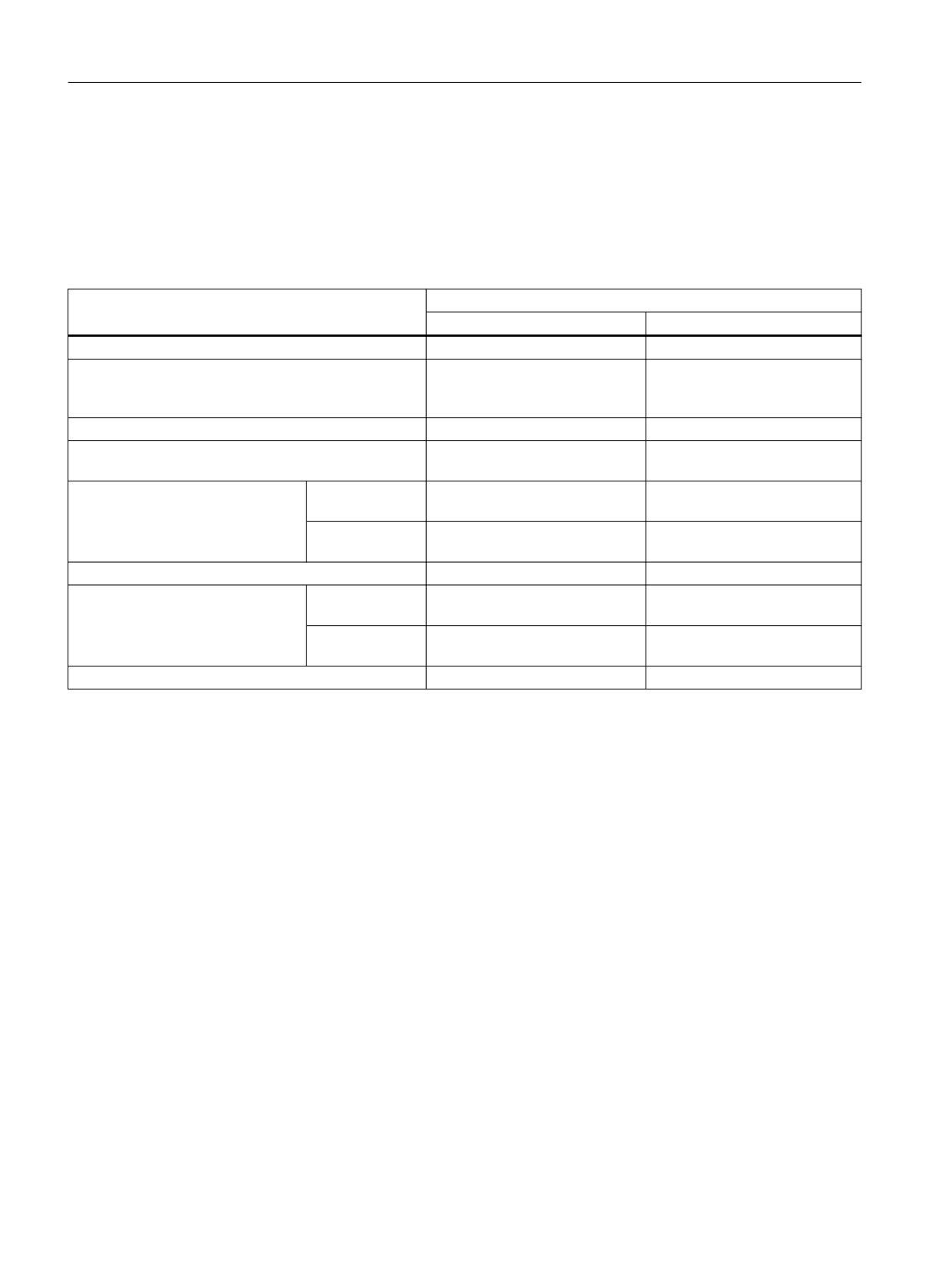
Table 9-8
Response times when controlling via PROFIsafe
Function
Worst case for
Drive system has no fault
A fault is present
STO
5 · p9500 + r9780 + t_K4)
5 · p9500 + 2 · r9780 + t_K4)
SS1
(speed controlled/time and acceleration controlled),
SS1E (time controlled)
5 · p9500 + 2 ms + t_K4)
5 · p9500 + 2 ms + t_K4)
SBC
5 · p9500 + 2 · r9780 + t_K4)
5 · p9500 + 6 · r9780 + t_K4)
SBR or SAM (limit value violation until STO active)
3 · p9500 + r9780 + p9587 + 4 ms
3,5 · p9500 + r9780 + p9587 +
32 ms
SLS speed limit violated 3)
Standard3)
3 · p9500 + p9587 + 6 ms
4,5 · p9500 + r9780 + p9587 +
32 ms
Start phase3)
3 · p9500 + p9587 + p95863) +
4,5 · p9500 + r9780 + p9587 +
6 ms
p95863) + 32 ms
SSM6)
6 · p9500 + p9587 + 4 ms
6,5 · p9500 + p9587 + 32 ms
SDI (limit value violation until brak-
Standard3)
2,5 · p9500 + p9587 + 6 ms
4 · p9500 + r9780 + p9587 +
ing is initiated)
32 ms
Start phase3)
2,5 · p9500 + p9587 + p95863) +
4 · p9500 + r9780 + p9587 +
6 ms
p95863) + 32 ms
SP7)
6 · p9500 + p9587 + 4 ms
6,5 · p9500 + p9587 + 32 ms
1)
The specified response times are valid for Extended Functions with and without selection!
2)
The specified response times involve internal SINAMICS response times. Program run times in the F-host and the
transmission time via PROFIBUS or PROFINET are not taken into account. When calculating the response times between
the F-CPU and the converter, you must take into account that faults in the communication can result in a safety function only
being selected after the PROFIsafe monitoring time (F_WD_Time) has expired. The PROFIsafe monitoring time
(F_WD_Time) must also be included in the calculation when an error occurs.
3)
Start phase: This describes the behavior after switching on (ON command with previously deleted pulses).
Standard: This behavior applies when the pulses have already been enabled.
There is a different behavior because, with the aid of p9586, the encoderless actual value acquisition after pulse enable can
only be activated after a delay.
4)
t_K is the time for internal communication within the SINAMICS module; t_K can be determined as follows:
Safety Integrated
364
Function Manual, 06/2020, 6SL3097-5AR00-0BP3

System features
9.4 Response times
For isochronous communication
t_K = To (for To, see parameter r2064[4])
For non-isochronous
t_K = 4 ms
communication
(for modules, on which p2048 or p88485) does not exist)
t_K = value from p2048 or p88485)
(for modules on which p2048 or p88485) exists)
5)
p2048 applies to communication via IF1, p8848 to communication via IF2.
6)
SSM: The data corresponds to the times between the limit value being undershot up to sending the information via
PROFIsafe.
7)
SP: The data corresponds to the times between acquisition of the safe position and transfer of the safe position via
PROFIsafe.
Safety Integrated
Function Manual, 06/2020, 6SL3097-5AR00-0BP3
365
System features
9.4 Response times
9.4.9
Control of Extended Functions without encoder via terminals (only CU310-2)
The table below shows the response times1) from the occurrence of a signal at the terminals
until the response is initiated.
CAUTION
Extension of the response times for SLS without encoder or SDI without encoder under certain
circumstances
If the safety functions SLS without encoder or SDI without encoder are already selected when
the gating pulses for the Power Module are enabled, then during the starting phase, it is
absolutely imperative that you take into account that the response times - when limit values
are violated and for system errors - are extended by the time value set in parameter p95862)
with respect to the standard values (see table above).
After the time interval set in p9586, the standard response times apply (see table above).
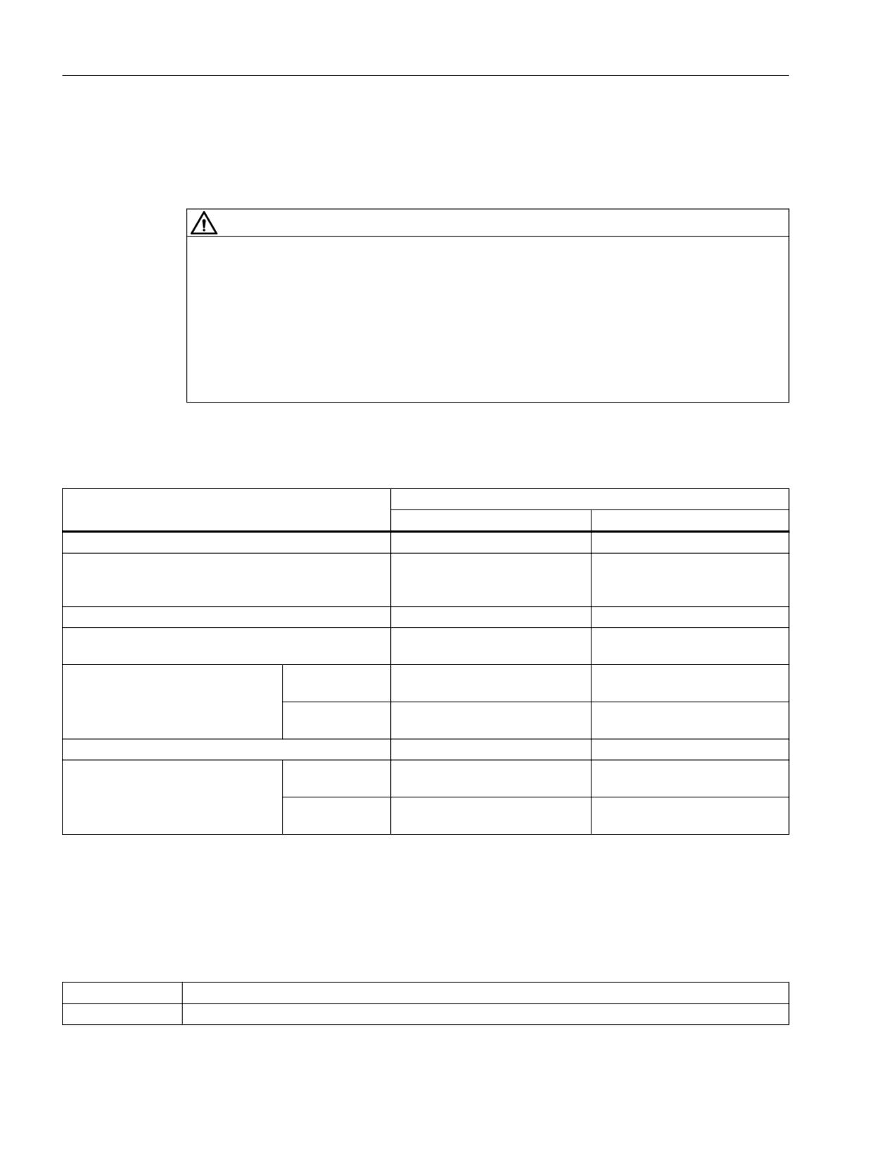
Table 9-9
Response times for control of the Extended Functions without encoder via terminals (only CU310-2)
Function
Worst case for
Drive system has no fault
A fault is present
STO
3,5 · p9500 + r9780 + t_E3)
4 · p9500 + 2 · r9780 + t_E3)
SS1
3,5 · p9500 + 2 ms + t_E3)
4 · p9500 + 2 ms + t_E3)
(speed controlled/time and acceleration controlled),
SS1E (time controlled)
SBC
3,5 · p9500 + 2 · r9780 + t_E3)
4 · p9500 + 9 · r9780 + t_E3)
SBR or SAM (limit value violation until STO active)
3 · p9500 + r9780 + p9587 + 4 ms
3,5 · p9500 + r9780 + p9587 +
32 ms
SLS speed limit violated 3)
Standard2)
3 · p9500 + p9587 + 6 ms
4,5 · p9500 + r9780 + p9578 +
32 ms
Start phase2)
3 · p9500 + p95862) + p9578 + 6
4,5 · p9500 + r9780 + p95862) +
ms
p9578 + 32 ms
SSM
4 · p9500 + p9587 + 4 ms
4,5 · p9500 + p9587 + 32 ms
SDI (limit value violation until
Standard2)
2,5 · p9500 + p9587 + 6 ms
4 · p9500 + r9780 + p9587 +
braking is initiated)
32 ms
Start phase2)
2,5 · p9500 + p9587 + p95862) +
4 · p9500 + r9780 + p9587 +
6 ms
p95862) + 32 ms
1)
The specified response times are valid for Extended Functions with and without selection!
2)
Start phase: This describes the behavior after switching on (ON command with previously deleted pulses).
Standard: This behavior applies when the pulses have already been enabled.
There is a different behavior because, with the aid of p9586, the encoderless actual value acquisition after pulse enable can
only be activated after a delay.
3)
For t_E, the following applies:
p10017 = 0
t_E = 2 · p0799
p10017 ≠ 0
t_E = p10017 + p0799 + 1 ms
Safety Integrated
366
Function Manual, 06/2020, 6SL3097-5AR00-0BP3
System features
9.4 Response times
9.4.10
Control of Extended Functions without encoder via TM54F (CU310-2 and
CU320-2)
The table below shows the response times1) from the occurrence of a signal at the terminals
until the response is initiated.
CAUTION
Extension of the response times for SLS without encoder or SDI without encoder under certain
circumstances
If the safety functions SLS without encoder or SDI without encoder are already selected when
the gating pulses for the Power Module are enabled, then during the starting phase, it is
absolutely imperative that you take into account that the response times - when limit values
are violated and for system errors - are extended by the time value set in parameter p95862)
with respect to the standard values (see table above).
After the time interval set in parameter p9586, the standard response times apply (see table
above).
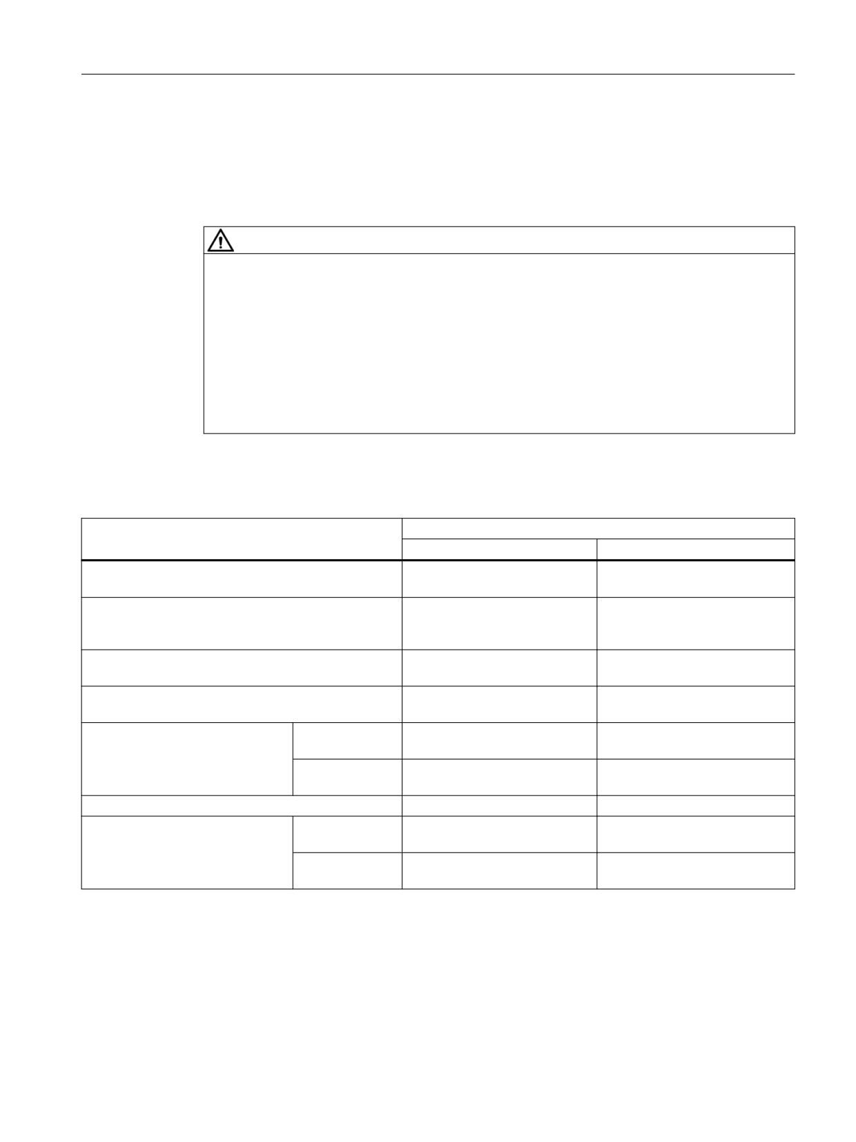
Table 9-10
Response times for control via TM54F
Function
Worst case for
Drive system has no fault
A fault is present
STO
3,5 · p9500 + r9780 + p100173) +
4 · p9500 + 2 · r9780 + p100173) +
1 ms
1 ms
SS1
(speed controlled/time and acceleration controlled),
SS1E (time controlled)
3,5 · p9500 + p100173) + 3 ms
4 · p9500 + p100173) + 3 ms
SBC
3,5 · p9500 + 2 · r9780 +
4 · p9500 + 6 · r9780 + p100173) +
p100173) + 1 ms
1 ms
SBR or SAM (limit value violation until STO active)
3 · p9500 + +r9780 + p9587 + 4
3,5 · p9500 + r9780 + p9587 +
ms
32 ms
SLS speed limit violated 3)
Standard2)
3 · p9500 + p9587 + 6 ms
4,5 · p9500 + r9780 + p9587 +
32 ms
Start phase2)
3 · p9500 + p9587 + p95862) + 6
4,5 · p9500 + r9780 + p9587 +
ms
p95862) + 32 ms
SSM
4 · p9500 + p9587 + 4 ms
4,5 · p9500 + p9587 + 32 ms
SDI (limit value violation until brak-
Standard2)
2,5 · p9500 + p9587 + 6 ms
4 · p9500 + r9780 + p9587 +
ing is initiated)
32 ms
Start phase2)
2,5 · p9500 + p9587 + p95862) +
4 · p9500 + r9780 + p9587 +
6 ms
p95862) + 32 ms
1)
The specified response times are valid for Extended Functions with and without selection!
2)
Start phase: This describes the behavior after switching on (ON command with previously deleted pulses).
Standard: This behavior applies when the pulses have already been enabled.
There is a different behavior because, with the aid of p9586, the encoderless actual value acquisition after pulse enable can
only be activated after a delay.
3)
For CU310-2, use the parameter p10017 of the drive object "TM54F_xx" to calculate the response time, not that of the
control unit.
Safety Integrated
Function Manual, 06/2020, 6SL3097-5AR00-0BP3
367

System features
9.4 Response times
9.4.11
Control of Advanced Functions with encoder via PROFIsafe (CU310-2 and
CU320-2)
The following table lists the response times1) from receiving the PROFIsafe telegram at the
Control Unit up to initiating the particular response.
Table 9-11
Response times when controlling via PROFIsafe
Function
Worst case for
Drive system has no fault
A fault is present
SLP (limit value violation until a response is initiated)
1.5 · p9500 + 2 ms
3 · p9500 + 2 ms + t_ACT2)
SP4) with isochronous PROFIsafe telegram
3 · p9500
3 · p9500 + t_ACT2)
SCA: Time between violation of a cam start or end po-
sition and output of the feedback message in
S_ZSW_CAM1
3.5 · p9500
4 · p9500 + t_ACT2)
1)
The specified response times involve internal SINAMICS response times. Program run times in the F-host and the
transmission time via PROFIBUS or PROFINET are not taken into account. When calculating the response times between
the F-CPU and the converter, you must take into account that faults in the communication can result in a safety function only
being selected after the PROFIsafe monitoring time (F_WD_Time) has expired. The PROFIsafe monitoring time
(F_WD_Time) must also be included in the calculation when an error occurs.
2)
t_ACT:
For isochronous communication
t_K = To (for To, see parameter r2064[4])
For non-isochronous
t_K = 4 ms
communication
(for modules, on which p2048 or p88487) does not exist)
t_K = value from p2048 or p88487)
(for modules on which p2048 or p88487) exists)
4)
SP: The data corresponds to the times between acquisition of the safe position and transfer of the safe position via
PROFIsafe.
Safety Integrated
368
Function Manual, 06/2020, 6SL3097-5AR00-0BP3

System features
9.4 Response times
9.4.12
Control of Advanced Functions with encoder via TM54F (CU310-2 and CU320-2)
The table below shows the response times after the appearance of a signal at the terminals.
Table 9-12
Response times for control via TM54F
Function
Worst case for
Drive system has no fault
A fault is present
SLP
(limit value violation until a response is initiated)
1,5 · p9500 + 2 ms
3 · p9500 + 2 ms + t_IST1)
1)
For t_ACT, the following applies:
For p9511 ≠ 0
t_ACT = p9511
For p9511 = 0
If an isochronous PROFIBUS master is available:
t_ACT = PROFIBUS cycle
Otherwise:
t_ACT = 1 ms
Safety Integrated
Function Manual, 06/2020, 6SL3097-5AR00-0BP3
369

System features
9.4 Response times
9.4.13
Control of Advanced Functions with encoder via terminals (only CU310-2)
The table below shows the response times after the appearance of a signal at the terminals.
Table 9-13
Response times when controlling the Advanced Functions with encoder via safe onboard terminals (only
CU310-2)
Function
Worst case for
Drive system has no fault
A fault is present
SLP (limit value violation until a response is initiated)
1,5 · p9500 + 2 ms
3 · p9500 + 2 ms + t_IST1)
1)
t_ACT:
For p9511 ≠ 0
t_ACT = p9511
For p9511 = 0
If an isochronous PROFIBUS master is available:
t_ACT = PROFIBUS cycle
Otherwise:
t_ACT = 1 ms
Safety Integrated
370
Function Manual, 06/2020, 6SL3097-5AR00-0BP3
System features
9.4 Response times
9.4.14
Advanced Functions without encoder via PROFIsafe (CU310-2 and CU320-2)
The following table lists the response times1) from receiving the PROFIsafe telegram at the
Control Unit up to initiating the particular response.
Table 9-14
Response times when controlling via PROFIsafe
Function
Worst case for
Drive system has no fault
A fault is present
SP2)
6 · p9500 + p9587 + 4 ms
6,5 · p9500 + p9587 + 32 ms
1)
The specified response times involve internal SINAMICS response times. Program run times in the F-host and the
transmission time via PROFIBUS or PROFINET are not taken into account. When calculating the response times between
the F-CPU and the converter, you must take into account that faults in the communication can result in a safety function only
being selected after the PROFIsafe monitoring time (F_WD_Time) has expired. The PROFIsafe monitoring time
(F_WD_Time) must also be included in the calculation when an error occurs.
2)
SP: The data corresponds to the times between acquisition of the safe position and transfer of the safe position via
PROFIsafe.
Safety Integrated
Function Manual, 06/2020, 6SL3097-5AR00-0BP3
371
System features
9.4 Response times
Safety Integrated
372
Function Manual, 06/2020, 6SL3097-5AR00-0BP3
Standards and regulations
10
10.1
General information
10.1.1
Aims
Manufacturers and operating companies of equipment, machines, and products are
responsible for ensuring the required level of safety. This means that plants, machines, and
other equipment must be designed to be as safe as possible in accordance with the current
state of the art. For this purpose, companies describe in the various standards the current state
of the art covering all aspects relevant to safety. If it can be justifiably assumed that all of the
relevant standards are complied with, this ensures that state-of-the-art technology has been
utilized and, in turn, a plant builder or a manufacturer of a machine or a piece of equipment has
fulfilled his appropriate responsibility.
Safety systems are designed to minimize potential hazards for both people and the
environment by means of suitable technical equipment, without restricting industrial production
and the use of machines more than is necessary. The protection of man and environment must
be assigned equal importance in all countries based on internationally harmonized rules and
regulations. This is also intended to avoid competitive advantages or disadvantages due to
different safety requirements in different countries.
There are different concepts and requirements in the various regions and countries of the world
when it comes to ensuring the appropriate degree of safety. The legislation and the
requirements of how and when proof is to be given and whether there is an adequate level of
safety are just as different as the assignment of responsibilities.
The most important thing for manufacturers of machines and companies that set up plants and
systems is that the legislation and regulations in the country where the machine or plant is being
operated apply. For example, the control system for a machine that is to be used in the US must
fulfill local US requirements even if the machine manufacturer (OEM) is based in the European
Economic Area (EEA).
Safety Integrated
Function Manual, 06/2020, 6SL3097-5AR00-0BP3
373
Standards and regulations
10.1 General information
10.1.2
Functional safety
Safety, from the perspective of the object to be protected, cannot be split-up. The causes of
hazards and, in turn, the technical measures to avoid them can vary significantly. This is why
a differentiation is made between different types of safety (e.g. by specifying the cause of
possible hazards). "Functional safety" is involved if safety depends on the correct function.
To ensure the functional safety of a machine or plant, the safety-related parts of the protection
and control devices must function correctly. In addition, the systems must behave in such a way
that either the plant remains in a safe state or it is brought into a safe state if a fault occurs. In
this case, it is necessary to use specially qualified technology that fulfills the requirements
described in the associated Standards. The requirements to implement functional safety are
based on the following basic goals:
● Avoiding systematic faults
● Controlling random faults or failures
Benchmarks for establishing whether or not a sufficient level of functional safety has been
achieved include the probability of hazardous failures, the fault tolerance, and the quality that
is to be ensured by avoiding systematic faults. This is expressed in the standards using specific
classification. In IEC/EN 61508, IEC/EN 62061 "Safety Integrity Level" (SIL) and
EN ISO 13849-1 "Category" and "Performance Level" (PL).
Safety Integrated
374
Function Manual, 06/2020, 6SL3097-5AR00-0BP3
Standards and regulations
10.2 Safety of machinery in Europe
10.2
Safety of machinery in Europe
The EU Directives that apply to the implementation of products are based on Article 95 of the
EU contract, which regulates the free exchange of goods. These are based on a new global
concept ("new approach", "global approach"):
● EU Directives only specify general safety goals and define basic safety requirements.
● Technical details can be defined by means of standards by Standards Associations that
have the appropriate mandate from the commission of the European Parliament and
Council (CEN, CENELEC). These standards are harmonized in line with a specific directive
and listed in the official journal of the commission of the European Parliament and Council.
Legislation does not specify that certain standards have to be observed. When the
harmonized Standards are observed, it can be assumed that the safety requirements and
specifications of the Directives involved have been fulfilled.
● EU Directives specify that the Member States must mutually recognize domestic
regulations.
The EU Directives are equal. This means that if several Directives apply for a specific piece of
equipment or device, the requirements of all of the relevant Directives apply (e.g. for a machine
with electrical equipment, the Machinery Directive and the Low-Voltage Directive apply).
10.2.1
Machinery Directive
The basic safety and health requirements specified in Annex I of the Directive must be fulfilled
for the safety of machines.
The protective goals must be implemented responsibly to ensure compliance with the Directive.
Manufacturers of a machine must verify that their machine complies with the basic
requirements. This verification is facilitated by means of harmonized standards.
IEC 61800-5-2 Adjustable-speed electrical power drive systems Part 5-2 is relevant for the
Machinery Directive: Safety requirements - Functional safety
Within the context of IEC 61508, IEC 61800-5-2 considers adjustable speed electric power
drive systems (PDS), which are suitable for use in safety-related applications (PDS(SR)).
IEC 61800-5-2 places demands on PDS(SR) as subsystems of a safety-related system. This
therefore permits the implementation of the electrical/electronic/programmable electronic
elements of a PDS(SR) taking into account the safety-relevant performance of the safety
function(s) of a PDS.
Manufacturers and suppliers of PDS(SR) can prove to users (e.g. integrators of control
systems, developers of machines and plants etc.) the safety-relevant performance of their
equipment by implementing the specifications stipulated in standard IEC 61800-5-2.
Safety Integrated
Function Manual, 06/2020, 6SL3097-5AR00-0BP3
375
Standards and regulations
10.2 Safety of machinery in Europe
10.2.2
Harmonized European Standards
The two Standards Organizations CEN (Comité Européen de Normalisation) and CENELEC
(Comité Européen de Normalisation Électrotechnique), mandated by the EU Commission,
drew-up harmonized European standards in order to precisely specify the requirements of the
EC directives for a specific product. These standards (EN standards) are published in the
official journal of the commission of the European Parliament and Council and must be included
without revision in domestic standards. They are designed to fulfill basic health and safety
requirements as well as the protective goals specified in Annex I of the Machinery Directive.
When the harmonized standards are observed, it is "automatically assumed" that the Directive
is fulfilled. As such, manufacturers can assume that they have observed the safety aspects of
the Directive under the assumption that these are also covered in this standard. However, not
every European Standard is harmonized in this sense. Key here is the listing in the official
journal of the commission of the European Parliament and Council.
The European Safety of Machines standard is hierarchically structured. It is divided into:
● A standards (basic standards)
● B standards (group standards)
● C standards (product standards)
Type A standards/basic standards
A standards include basic terminology and definitions relating to all types of machine. This
includes EN ISO 12100 (previously EN 292-1) "Safety of Machines, Basic Terminology,
General Design Principles".
A standards are aimed primarily at the bodies responsible for setting the B and C standards.
The measures specified here for minimizing risk, however, may also be useful for
manufacturers if no applicable C standards have been defined.
Type B standards/group standards
B standards cover all safety-related standards for various different machine types. B standards
are aimed primarily at the bodies responsible for setting C standards. They can also be useful
for manufacturers during the machine design and construction phases, however, if no
applicable C standards have been defined.
A further sub-division has been made for B standards:
● Type B1 standards for higher-level safety aspects (e.g. ergonomic principles, safety
clearances from sources of danger, minimum clearances to prevent parts of the body from
being crushed).
● Type B2 standards for protective safety devices are defined for different machine types (e.g.
EMERGENCY STOP devices, two-hand operating circuits, interlocking elements,
contactless protective devices, safety-related parts of controls).
Type C standards/product standards
C standards are product-specific standards (e.g. for machine tools, woodworking machines,
elevators, packaging machines, printing machines etc.). Product standards cover machine-
specific requirements. The requirements can, under certain circumstances, deviate from the
basic and group standards. Type C/product standards have the highest priority for machine
manufacturers who can assume that it fulfills the basic requirements of Annex I of the
Machinery Directive (automatic presumption of compliance). If no product standard has been
Safety Integrated
376
Function Manual, 06/2020, 6SL3097-5AR00-0BP3
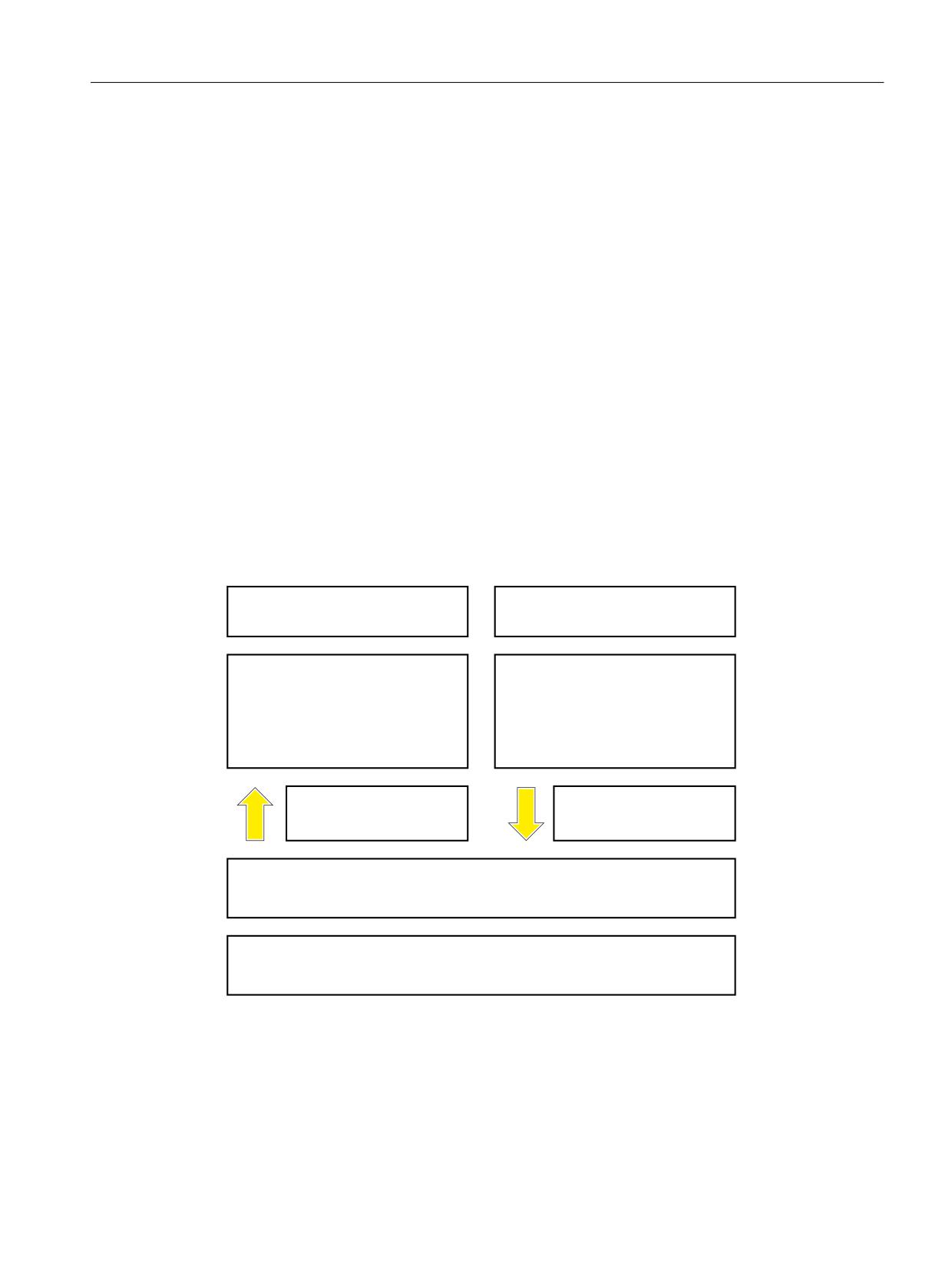
Standards and regulations
10.2 Safety of machinery in Europe
defined for a particular machine, type B standards can be applied when the machine is
constructed.
A complete list of the standards specified and the mandated draft standards are available on
the Internet at the following address:
Recommendation: Due to the rapid pace of technical development and the associated changes
in machine concepts, the standards (and C standards in particular) should be checked to
ensure that they are up to date. Please note that the application of a particular standard may not
be mandatory provided that all the safety requirements of the applicable EU directives are
fulfilled.
10.2.3
Standards for implementing safety-related controllers
If the functional safety of a machine depends on various control functions, the controller must
be implemented in such a way that the probability of safety functions failing in a dangerous
fashion is sufficiently minimized. The EN ISO 13849-1 and IEC61508 standards define
principles for implementing safety-related machine controllers which, when properly applied,
ensure that all the safety requirements of the EC Machinery Directive are fulfilled. These
standards ensure that the relevant safety requirements of the Machinery Directive are fulfilled.
$Q\ DUFKLWHFWXUHV
'HILQHG DUFKLWHFWXUHV UHVWULFWHG PD[LPXP
$OO 6,/
IURP 3/ E
3/ IRU HOHFWURQLFV
(1
(1 ,62
6DIHW\ RI 0DFKLQHU\
6DIHW\ RI 0DFKLQHU\
)XQFWLRQDO VDIHW\ VDIHW\ UHODWHG
6DIHW\ UHODWHG SDUWV RI FRQWURO V\VWHPV
HOHFWULFDO HOHFWURQLF DQG SURJUDPPDEOH
HOHFWURQLF FRQWURO V\VWHPV
6HFWRU 6WDQGDUG (1
IRU
)RU GHYLDWLRQV IURP WKH GHILQHG
WKH DUHD RI PDFKLQHV EHORZ (1
DUFKLWHFWXUHV UHIHUHQFH WR (1
8QLYHUVDO XVH IRU HOHFWULFDO HOHFWURQLF DQG SURJUDPPDEOH HOHFWURQLF V\VWHPV WKDW H[HFXWH
VDIHW\ IXQFWLRQV RU JXDUDQWHH IXQFWLRQDO VDIHW\
(1
)XQFWLRQDO VDIHW\ VDIHW\ UHODWHG HOHFWULFDO HOHFWURQLF SURJUDPPDEOH HOHFWURQLF FRQWURO
V\VWHPV 3DUW WR
Figure 10-1
Standards for implementing safety-related controllers
The application areas of EN ISO 13849-1, EN 62061, and EN 61508 are very similar. To help
users make an appropriate decision, the IEC and ISO associations have specified the
application areas of both standards in a joint table in the introduction to the standards.
EN ISO 13849-1 or EN 62061 should be applied depending on the technology (mechanics,
hydraulics, pneumatics, electrics, electronics, programmable electronics), risk classification
and architecture.
Safety Integrated
Function Manual, 06/2020, 6SL3097-5AR00-0BP3
377

Standards and regulations
10.2 Safety of machinery in Europe
Further, Standard IEC 61800-5-2 is applicable for variable-speed electric drives with integrated
safety functions. IEC 61800-5-2 defines requirements and gives recommendations for
designing and developing, integrating and validating safety-related applications regarding their
functional safety. IEC 61800-5-2 is applicable for adjustable speed electric power drive
systems, which are handled in other parts of IEC 61800 standards.
Systems for executing safety-related control
EN ISO 13849-1
EN 62061
functions
A
Non-electrical (e.g. hydraulic, pneumatic)
X
Not covered
B
Electromechanical (e.g. relay and/or basic elec-
Restricted to the designated ar-
All architectures and max. up to
tronics)
chitectures (see comment 1) and
SIL 3
max. up to PL = e
C
Complex electronics (e.g. programmable elec-
Restricted to the designated ar-
All architectures and max. up to
tronics)
chitectures (see comment 1) and
SIL 3
max. up to PL = d
D
A standards combined with B standards
Restricted to the designated ar-
X
chitectures (see comment 1) and
See comment 3
max. up to PL = e
E
C standards combined with B standards
Restricted to the designated ar-
All architectures and max. up to
chitectures (see comment 1) and
SIL 3
max. up to PL = d
F
C standards combined with A standards
X
X
or
C standards combined with A standards and B
See comment 2
See comment 3
standards
"X" indicates that the point is covered by this standard.
Comment 1:
Designated architectures are described in Annex B of EN ISO 13849-1 and provide a simplified basis for the quantification.
Comment 2:
For complex electronics: Using designated architectures in compliance with EN ISO 13849-1 up to PL = d or every architecture
in compliance with EN 62061.
Comment 3:
For non-electrical systems: Use components that comply with EN ISO 13849-1 as sub-systems.
Safety Integrated
378
Function Manual, 06/2020, 6SL3097-5AR00-0BP3
Standards and regulations
10.2 Safety of machinery in Europe
10.2.4
DIN EN ISO 13849-1
A qualitative analysis according to DIN EN 13849-1 is not sufficient for modern control systems
due to their technology. Among other things, DIN EN ISO 13849-1 does not take into account
time behavior (e.g. test interval and/or cyclic test, lifetime). This results in the probabilistic
approach in DIN EN ISO 13849-1 (probability of failure per unit time).
DIN EN ISO 13849-1 considers complete safety functions and all the devices required to
execute these. With DIN EN ISO 13849-1, safety functions are considered from both a
qualitative as well as a quantitative perspective. Performance levels (PL), which are based on
specific categories, are used. The following safety-related characteristic quantities are required
for devices/equipment:
● Category (structural requirement)
● PL: Performance level
● MTTFd: Mean time to dangerous failure
● DC: Diagnostic coverage
● CCF:
Common cause failure
The standard describes how the performance level (PL) is calculated for safety-related
components of the controller on the basis of designated architectures. For deviations from this,
DIN EN ISO 13849-1 refers to IEC 61508.
When combining several safety-related parts to form a complete system, the standard explains
how to determine the resulting PL.
Note
DIN EN ISO 13849-1 and machinery directive
Since May 2007, DIN EN ISO 13849-1 has been harmonized as part of the Machinery Directive.
10.2.5
EN 62061
EN 62061 (this is identical to IEC 62061) is a sector-specific standard below IEC/EN 61508. It
describes the implementation of safety-related electrical control systems of machines and
takes into account the complete lifecycle - from the conceptual phase to de-commissioning.
The standard is based on the quantitative and qualitative analyses of safety functions,
whereby it systematically applies a top-down approach to implementing complex control
systems (known as "functional decomposition"). The safety functions derived from the risk
analysis are sub-divided into sub-safety functions, which are then assigned to real devices, sub-
systems, and sub-system elements. Both the hardware and software are covered. EN 62061
also describes the requirements placed on implementing application programs.
A safety-related control systems comprises different sub-systems. From a safety perspective,
the sub-systems are described in terms of the SIL claim limit and PFHD characteristic
quantities.
Safety Integrated
Function Manual, 06/2020, 6SL3097-5AR00-0BP3
379
Standards and regulations
10.2 Safety of machinery in Europe
Programmable electronic devices (e.g. PLCs or variable-speed drives) must fulfill IEC 61508.
They can then be integrated in the controller as sub-systems. The following safety-related
characteristic quantities must be specified by the manufacturers of these devices.
Safety-related characteristic quantities for subsystems:
● SIL CL: SIL claim limit
● PFHD:
Probability of dangerous failures per hour
● T1:
Lifetime
Simple sub-systems (e.g. sensors and actuators) in electromechanical components can, in
turn, comprise sub-system elements (devices) interconnected in different ways with the
characteristic quantities required for determining the relevant PFHD value of the sub-system.
Safety-related characteristic quantities for subsystem elements (devices):
● λ:
Failure rate
● B10 value: For elements that are subject to wear
● T1:
Lifetime
For electromechanical devices, a manufacturer specifies a failure rate λ with reference to the
number of operating cycles. The failure rate per unit time and the lifetime must be determined
using the switching frequency for the particular application.
Parameters for the sub-system, which comprises sub-system elements, that must be defined
during the design phase:
● T2:
Diagnostic test interval
● β:
Susceptibility to common cause failure
● DC:
Diagnostic coverage
The PFHD value of the safety-related controller is determined by adding the individual PFHD
values for subsystems.
The user has the following options when setting up a safety-related controller:
● Use devices and sub-systems that already comply with EN ISO 13849-1, IEC/EN 61508, or
IEC/EN 62061. The standard provides information specifying how qualified devices can be
integrated when safety functions are implemented.
● Develop own subsystems:
- Programmable, electronic systems and complex systems: Application of IEC 61508 or
IEC 61800-5-2.
- Simple devices and subsystems: Application of EN 62061.
Safety Integrated
380
Function Manual, 06/2020, 6SL3097-5AR00-0BP3
Standards and regulations
10.2 Safety of machinery in Europe
EN 62061 does not include information about non-electric systems. The standard provides
detailed information on implementing safety-related electrical, electronic, and programmable
electronic control systems. DIN EN ISO 13849-1 must be applied for non-electric systems.
Note
Function examples
Details of simple sub-systems that have been implemented and integrated are now available
as "functional examples".
Note
EN 62061 and machinery directive
IEC 62061 has been ratified as EN 62061 in Europe and harmonized as part of the Machinery
Directive.
10.2.6
Series of standards IEC 61508 (VDE 0803)
This series of standards describes the current state of the art.
IEC 61508 is not harmonized in line with any EU directives, which means that an automatic
presumption of conformity for fulfilling the protective requirements of a directive is not implied.
The manufacturer of a safety-related product, however, can also use IEC 61508 to fulfill basic
requirements of European directives in accordance with the latest conceptual design, for
example, in the following cases:
● If no harmonized standard exists for the application in question. In this particular case, the
manufacturer may use IEC 61508. although no presumption of conformity exists here.
● A harmonized European standard (e.g. EN 62061, EN ISO 13849, EN 60204-1) references
IEC 61508. This ensures that the appropriate requirements of the directives are fulfilled
("standard that is also applicable"). When manufacturers apply IEC 61508 properly and
responsibly in accordance with this reference, they can use the presumption of conformity
of the referencing standard.
IEC 61508 covers all the aspects that must be taken into account when E/E/PES systems
(electrical, electronic, and programmable electronic system) are used in order to execute safety
functions and/or to ensure the appropriate level of functional safety. Other hazards (e.g. electric
shock) are not part of the standard, similar to DIN ISO 13849.
IEC 61508 has recently been declared the "International Basic Safety Publication", which
makes it a framework for other sector-specific standards (e.g. EN 62061). As a result, this
standard is now accepted worldwide, particularly in North America and in the automotive
industry. Today, many regulatory bodies already stipulate it (e.g. as a basis for NRTL listing).
Another recent development with respect to IEC 61508 is its system approach, which extends
the technical requirements to include the entire safety installation from the sensor to the
actuator, the quantification of the probability of hazardous failure due to random hardware
failures, and the creation of documentation covering all phases of the safety-related lifecycle of
the E/E/PES.
Safety Integrated
Function Manual, 06/2020, 6SL3097-5AR00-0BP3
381
Standards and regulations
10.2 Safety of machinery in Europe
10.2.7
Risk analysis/assessment
Risks are intrinsic in machines due to their design and functionality. For this reason, the
Machinery Directive requires that a risk assessment be performed for each machine and, if
necessary, the level of risk reduced until the residual risk is less than the tolerable risk. To
assess these risks, the following standards must be applied:
● EN ISO 12100 "Safety of Machinery - General Design Principles - Risk Assessment and
Minimizing Risks"
● EN ISO 13849-1 "Safety-related parts of control systems"
EN ISO 12100 focuses on the risks to be analyzed and the design principles for minimizing risk.
The risk assessment is a procedure that allows hazards resulting from machines to be
systematically investigated. Where necessary, the risk assessment is followed by a risk
reduction procedure. When the procedure is repeated, this is known as an iterative process.
This can help eliminate hazards (as far as this is possible) and can act as a basis for
implementing suitable protective measures.
The risk assessment involves the following:
● Risk analysis
- Determines the limits of the machine (EN ISO 12100)
- Identification of hazards (EN ISO 12100)
- Estimating the level of risk (EN 1050 Paragraph 7)
● Risk evaluation
As part of the iterative process to achieve the required level of safety, a risk assessment is
carried out after the risk estimation. A decision must be made here as to whether the residual
risk needs to be reduced. If the risk is to be further reduced, suitable protective measures must
be selected and applied. The risk assessment must then be repeated.
Safety Integrated
382
Function Manual, 06/2020, 6SL3097-5AR00-0BP3
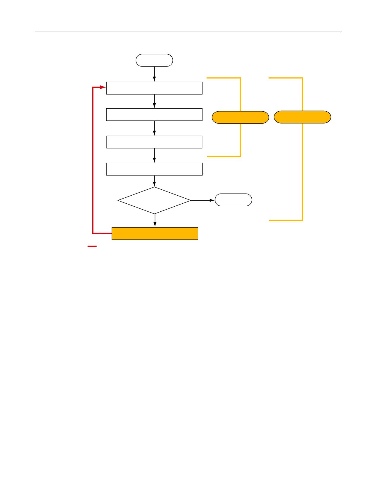
Standards and regulations
10.2 Safety of machinery in Europe
67
$57
'HWHUPLQLQJ WKH PDFKLQH OLPLWV
,GHQWLI\LQJ WKH SRWHQWLDO KD]DUG
5LVN DQDO\VLV
5LVN DVVHVVPHQW
5LVN HVWLPDWLRQ
5LVN HYDOXDWLRQ
<HV
,V WKH PDFKLQH VDIH
(1'
1R
5LVN UHGXFWLRQ
0LQLPL]LQJ ULVNV DQG VHOHFWLQJ VXLWDEOH SURWHFWLYH PHDVXUHV DUH QRW SDUW RI WKH ULVN DVVHVVPHQW
Figure 10-2
Iterative process for achieving safety
Risks must be reduced by designing and implementing the machine accordingly (e.g. by means
of controllers or protective measures suitable for the safety-related functions).
If the protective measures involve the use of interlocking or control functions, these must be
designed according to EN ISO 13849-1. For electrical and electronic control systems,
EN 62061 can be applied instead of EN ISO 13849-1. Electronic controllers and bus systems
must also comply with IEC 61508.
Safety Integrated
Function Manual, 06/2020, 6SL3097-5AR00-0BP3
383
Standards and regulations
10.2 Safety of machinery in Europe
10.2.8
Risk reduction
Risk reduction measures for a machine can be implemented by means of safety-related control
functions in addition to structural measures. To implement these control functions, special
requirements must be taken into account, graded according to the magnitude of the risk. These
are described in EN ISO 13849-1 or, in the case of electrical controllers (particularly
programmable electronics), in EN 61508 or EN 62061. The requirements regarding safety-
related controller components are graded according to the magnitude of the risk and the level
to which the risk needs to be reduced.
EN ISO 13849-1 defines a risk flow chart that instead of categories results in hierarchically
graduated Performance Levels (PL).
IEC/EN 62061 uses "Safety Integrity Level" (SIL) for classification purposes. This is a
quantified measure of the safety-related performance of a controller. The required SIL is also
determined in accordance with the risk assessment principle according to ISO 12100 (EN
1050). Annex A of the standard describes a method for determining the required Safety
Integrity Level (SIL).
Regardless of which standard is applied, steps must be taken to ensure that all the machine
controller components required for executing the safety-related functions fulfill these
requirements.
10.2.9
Residual risk
In today's technologically advanced world, the concept of safety is relative. The ability to ensure
safety to the extent that risk is ruled out in all circumstances - "zero-risk guarantee" - is
practically impossible. The residual risk is the risk that remains once all the relevant protective
measures have been implemented in accordance with the latest state of the art.
Residual risks must be clearly referred to in the machine/plant documentation (user information
according to EN ISO 12100).
10.2.10
EC declaration of conformity
The EC Declaration of Conformity for the product can be obtained from your local Siemens
office or in the Internet at:
Safety Integrated
384
Function Manual, 06/2020, 6SL3097-5AR00-0BP3
Standards and regulations
10.3 Machine safety in the USA
10.3
Machine safety in the USA
A key difference between the USA and Europe in the legal requirements regarding safety at
work is that, in the USA, no legislation exists regarding machinery safety that is applicable in all
of the states and that defines the responsibility of the manufacturer/supplier. A general
requirement exists stating that employers must ensure a safe workplace.
You can find further information in the following sections:
● Minimum requirements of the OSHA (Page 385)
● NRTL listing (Page 386)
● NFPA 79 (Page 387)
● ANSI B11 (Page 387)
10.3.1
Minimum requirements of the OSHA
The Occupational Safety and Health Act (OSHA) from 1970 regulates the requirement that
employers must offer a safe place of work. The core requirements of OSHA are specified in
Section 5 "Duties".
The requirements of the OSH Act are managed by the "Occupational Safety and Health
Administration" (also known as OSHA). OSHA employs regional inspectors who check whether
or not workplaces comply with the applicable regulations.
The OSHA regulations are described in OSHA 29 CFR 1910.xxx ("OSHA Regulations (29
CFR) PART 1910 Occupational Safety and Health"). (CFR: Code of Federal Regulations.)
The application of standards is regulated in 29 CFR 1910.5 "Applicability of standards". The
concept is similar to that used in Europe. Product-specific standards have priority over general
standards insofar as they cover the relevant aspects. Once the standards are fulfilled,
employers can assume that they have fulfilled the core requirements of the OSH Act with
respect to the aspects covered by the standards.
In conjunction with certain applications, OSHA requires that all electrical equipment and
devices that are used to protect workers be authorized by an OSHA-certified, "Nationally
Recognized Testing Laboratory" (NRTL) for the specific application.
In addition to the OSHA regulations, the current standards defined by organizations such as
NFPA and ANSI must be carefully observed and the extensive product liability legislation that
exists in the US taken into account. Due to the product liability legislation, it is in the interests
of manufacturing and operating companies that they carefully maintain the applicable
regulations and are "forced" to fulfill the requirement to use state-of-the-art technology.
Third-party insurance companies generally demand that their customers fulfill the applicable
standards of the standards organizations. Self-insured companies are not initially subject to
this requirement but, in the event of an accident, they must provide verification that they have
applied generally-recognized safety principles.
Safety Integrated
Function Manual, 06/2020, 6SL3097-5AR00-0BP3
385
Standards and regulations
10.3 Machine safety in the USA
10.3.2
NRTL listing
To protect employees, all electrical equipment used in the USA must be certified for the planned
application by a "Nationally Recognized Testing Laboratory" (NRTL) certified by the OSHA.
NRTLs are authorized to certify equipment and material by means of listing, labeling, or similar.
Domestic standards (e.g. NFPA 79) and international standards (e.g. IEC/EN 61508 for E/E/
PES systems) are the basis for testing.
Safety Integrated
386
Function Manual, 06/2020, 6SL3097-5AR00-0BP3
Standards and regulations
10.3 Machine safety in the USA
10.3.3
NFPA 79
Standard NFPA 79 (Electrical Standard for Industrial Machinery) applies to electrical
equipment on industrial machines with rated voltages of less than 600 V. A group of machines
that operate together in a coordinated fashion is also considered to be one machine.
For programmable electronics and communication buses, NFPA 79 states as a basic
requirement that these must be listed if they are to be used to implement and execute safety-
related functions. If this requirement is fulfilled, then electronic controls and communication
buses can also be used for Emergency Stop functions, Stop Categories 0 and 1 (refer to
NFPA 79 9.2.5.4.1.4). Just the same as EN 60204-1, NFPA 79 no longer specifies that the
electrical energy must be disconnected by electromechanical means for emergency stop
functions.
The core requirements regarding programmable electronics and communication buses in
accordance with NFPA 79 9.4.3:
1. Control systems that contain software-based controllers must:
- In the event of a single fault
(a) Initiate that the system switches to a safe shutdown mode
(b) Prevent the system from restarting until the fault has been rectified
(c) Prevent an unexpected restart
- Offer the same level of protection as hard-wired controllers
- Be implemented in accordance with a recognized standard that defines the requirements
for such systems.
2. IEC 61508, IEC 62061, ISO 13849-1, ISO 13849-2 and IEC 61800-5-2 are specified as
suitable standards in a note.
Underwriter Laboratories Inc. (UL) has defined a special category for "Programmable Safety
Controllers" for implementing this requirement (code NRGF). This category covers control
devices that contain software and are designed for use in safety-related functions.
A precise description of the category and a list of devices that fulfill this requirement can be
found on the Internet at the following address:
information → search for category "NRGF"
TUV Rheinland of North America, Inc. is also an NRTL for these applications.
10.3.4
ANSI B11
ANSI B11 standards are joint standards developed by associations such as the Association for
Manufacturing Technology (AMT) and the Robotic Industries Association (RIA).
The hazards of a machine are evaluated by means of a risk analysis/assessment. The risk
analysis is an important requirement in accordance with NFPA 79, ANSI/RIA 15.06, ANSI
B11.TR-3 and SEMI S10 (semiconductors). The documented results of a risk analysis can be
used to select a suitable safety system based on the safety class of the application in question.
Safety Integrated
Function Manual, 06/2020, 6SL3097-5AR00-0BP3
387

Standards and regulations
10.4 Machine safety in Japan
10.4
Machine safety in Japan
The situation in Japan is different from that in Europe and the US. Legislation such as that
prescribed in Europe does not exist. Similarly, product liability does not play such an important
role as it does in the US.
Instead of legal requirements to apply standards have been defined, an administrative
recommendation to apply JIS (Japanese Industrial Standard) is in place. Japan bases its
approach on the European concept and uses basic standards as national standards:
Table 10-1
Japanese standards
ISO/IEC number
JIS number
Comment
ISO12100 (EN 1050)
JIS B 9700, JIS B 9702
Earlier designation TR B 0008 and TR B 0009
ISO13849-1
JIS B 9705-1
-
ISO13849-2
JIS B 9705-1
-
IEC 60204-1
JIS B 9960-1
Without annex F or route map of the Europe-
an foreword
IEC 61508-0 to -7
JIS C 0508
-
IEC 62061
-
JIS number not yet assigned
Safety Integrated
388
Function Manual, 06/2020, 6SL3097-5AR00-0BP3
Standards and regulations
10.5 Equipment regulations
10.5
Equipment regulations
In addition to the requirements of the guidelines and standards, company-specific
requirements must be taken into account. Large corporations in particular (e.g. automobile
manufacturers) make stringent demands regarding automation components, which are often
listed in their own equipment specifications.
Safety-related issues (e.g. operating modes, operator actions with access to hazardous areas,
EMERGENCY STOP concepts, etc.) should be clarified with customers early on so that they
can be integrated in the risk assessment/risk reduction process.
Safety Integrated
Function Manual, 06/2020, 6SL3097-5AR00-0BP3
389
Standards and regulations
10.6 Other safety-related issues
10.6
Other safety-related issues
10.6.1
Information sheets issued by the Employer's Liability Insurance Association
Safety-related measures to be implemented cannot always be derived from directives,
standards, or regulations. In this case, supplementary information and explanations are
required.
Some regulatory bodies issue publications on an extremely wide range of subjects.
Note
These publications are in German. In some instances, they are also available in English and
French.
Information sheets covering the following areas are available, for example:
● Process monitoring in production environments
● Axes subject to gravitational force
● Roller pressing machines
● Lathes and turning centers - purchasing/selling
These information sheets issued by specialist committees can be obtained by all interested
parties (e.g. to provide support in factories, or when regulations or safety-related measures for
plants and machines are defined). These information sheets provide support for the fields of
machinery construction, production systems, and steel construction.
(website is in German, although some of the sheets are available in English):
1. First select the area "Arbeitsschützer", followed by the menu item "Praxishilfen" and finally
"DGUV-Informationen".
10.6.2
Additional references
● Safety Integrated, The Safety Program for Industries of the World (5th Edition and
Supplement), Article No. 6ZB5 000-0AA01-0BA1
● Safety Integrated - Terms and Standards - Machine Safety Terminology (Edition 04/2007),
Article No. E86060-T1813-A101-A1
Safety Integrated
390
Function Manual, 06/2020, 6SL3097-5AR00-0BP3
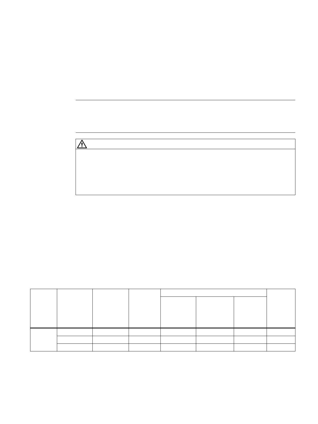
Maintenance
11
11.1
Information pertaining to component replacements
Note
Note additional safety instructions
Observe the instructions with regard to changing or replacing software components in Chapter
"Safety instructions (Page 23)"!
WARNING
Unwanted motion if components are replaced without a function test
After a component replacement, connections or functions can be defective so that death or
serious injury can result if a person enters the danger zone of the motors.
● After component replacement, always run a simplified function test.
You can find more detailed information in Chapters "Test scope for specific measures
(Page 339)" and "Acceptance test (Page 331)".
The faulty component was replaced according to safety regulations. The information relevant
from the perspective of Safety Integrated is provided in the following. For information about
component replacements, see "Example of component replacements" in the SINAMICS S120
Function Manual Drive Functions.
● Based on the NodeID and the saved CRC of the particular hardware component, the drive
identifies that a component has been replaced. You can take the responses of the drive and
the actions that have to be carried out from the table in the following section:
11.1.1
Details on the replacement of individual components
Replaced
Control type
Drive re-
User action
Diagnostic
component
sponse
parameters
Fault acknowl-
Acknowledg-
Save3)
(fault)
edgment re-
ment is re-
quired1)
quired that the
component has
been replaced2)
Basic
Control Unit
All
F01641.0 = 1
Yes
No
Yes
r9776.2 = 1
Functions Motor Module
All
F01641.1 = 1
Yes
No
Yes
r9776.2 = 1
Power Module
All
F01641.2 = 1
Yes
No
Yes
r9776.2 = 1
Safety Integrated
Function Manual, 06/2020, 6SL3097-5AR00-0BP3
391

Maintenance
11.1 Information pertaining to component replacements
Replaced
Control type
Drive re-
User action
Diagnostic
component
sponse
parameters
Fault acknowl-
Acknowledg-
Save3)
(fault)
edgment re-
ment is re-
quired1)
quired that the
component has
been replaced2)
Extended/
Control Unit
All
F01641.0 = 1
Yes
No
Yes
r9776.2 = 1
Advanced
Motor Module
PROFIsafe,
F01641.1 = 1
Yes
No
Yes
r9776.2 = 1
Functions
OnBoard F-DI,
without selec-
tion
TM54F
F01640.1 = 1
Yes
Yes
Yes
r9776.2 = 1
r9776.3 = 1
Power Module
All
F01641.2 = 1
Yes
No
Yes
r9776.2 = 1
Sensor
All
F01641.3 = 1
Yes
No
Yes
r9776.2 = 1
Module
(CPU 1)
Sensor
All
F01640.4 = 1
Yes
Yes
Yes
r9776.2 = 1
Module
r9776.3 = 1
(CPU 2)
Encoder4)
All
F01641.5 = 1
Yes
No
Yes
r9776.2 = 1
F01641.6 = 1
TM54F
All
F01641
Yes
No
Yes
r9776.2 = 1
(only on
TM54F_MA)
1)
The fault must be acknowledged each time a component is replaced using a standard acknowledgment (e.g. using a 0/1
signal at p2103). However, even without acknowledgment the drive can still be operated.
2)
The replacement of the components listed in the table must be acknowledged in order to ensure the new internal device
communications to be established. When replacing other components, acknowledgment is not required, as the new
communications to be established are automatically ensured.
To acknowledge a component replacement, perform the following sequence on all of the drive objects involved:
- Check whether the following preconditions are fulfilled:
- p0010 = 0
- It is not permissible for a firmware update to be active on the drive object.
- Set p9702 = 29 (= 1D hex)
- When the acknowledgement process is finished, p9702 jumps back to the value 0.
3)
The modified data must be saved after a component has been replaced:
- It is not permissible for a firmware update to be active on the drive object.
- Copy from RAM to ROM by setting p0977 = 1.
If the data is not saved, the fault is output again after the next POWER ON.
4)
Only for encoders with serial number (e.g. EnDat)
Safety Integrated
392
Function Manual, 06/2020, 6SL3097-5AR00-0BP3
Maintenance
11.1 Information pertaining to component replacements
11.1.2
Replacing motors for safety without encoder
When using safety functions without encoder, the motor pole pair number plays a decisive role.
If a motor is replaced, then the behavior depends on the pole pair number: If a motor with a
higher pole pair number is used (other than that configured), the mechanical speed is less than
that calculated by Safety Integrated. If a motor with a lower pole pair number is used (e.g. when
a motor is replaced), the mechanical speed is higher than that calculated by Safety Integrated.
● After a replacement such as this, perform a test by comparing the safe actual speed (r9714)
with the normal speed (r0063 or the output frequency), and if required, correct the
configured pole pair number.
11.1.3
Parameters and function diagrams
Overview of important parameters (see SINAMICS S120/S150 List Manual)
● r9670
SI module identification Control Unit
● r9671[0...n]
SI module identification Motor Module
● p9672
SI module identification Power Module
● p9673
SI module identification sensor channel 1
● p9674
SI module identification sensor channel 2
● p9675
SI module identification sensor channel 1
● p9676
SI module identification sensor channel 2
● p9702
Acknowledge SI component replacement
● r9776
SI diagnostics
● r9793[0...9]
SI diagnostics component replacement
● r10070
SI TM54F module identification
Safety Integrated
Function Manual, 06/2020, 6SL3097-5AR00-0BP3
393

Maintenance
11.2 Note regarding firmware update
11.2
Note regarding firmware update
WARNING
Firmware update without POWER ON and acceptance test
If the message A01007 "POWER ON required for DRIVE-CLiQ component" appears after a
firmware update, death or serious injury can be caused if a person enters the danger zone of
the motors.
● Then perform a partial acceptance test.
● Do not enter the danger zone of the motor until the acceptance test has been successfully
completed.
WARNING
Unwanted motion if components are replaced without a function test
After a component replacement, connections or functions can be defective so that death or
serious injury can result if a person enters the danger zone of the motors.
● Perform a POWER ON before resuming operation.
● After component replacement, always run a simplified function test.
You can find more detailed information in Chapters "Test scope for specific measures
(Page 339)" and "Acceptance test with Startdrive (Page 343)".
Safety Integrated
394
Function Manual, 06/2020, 6SL3097-5AR00-0BP3

Maintenance
11.3 Safety faults
11.3
Safety faults
11.3.1
Stop responses
Possible stop responses
Faults with Safety Integrated Extended/Advanced Functions and violation of limits can initiate
the following stop responses:
Overview of stop responses
Table 11-1
Overview of stop responses
Stop response
Triggered ...
Action
Effect
STOP A1)
● For all acknowledgeable
Immediate pulse suppression
Drive coasts down
(corresponds to
safety faults with pulse
STO2))
suppression
● Subsequent response of
STOP B
● Configurable subsequent
stop p9563 for SLS
● Configurable subsequent
stop p9566 for SDI
● Configurable subsequent
stop p9562 for SLP
● Configurable subsequent
stop p9579 for SLA
STOP B1)
Examples:
Immediate input of speed set-
STOP B with subsequent STOP A.
(corresponds to
point = 0 and start of timer tB .
● Standstill tolerance viola-
The drive decelerates along the
SS13))
Once tB or nact < nshutdown has ex-
ted in p9530 (SOS)
OFF3 ramp and then switches to
pired, STOP A is triggered.
STOP A.
● Configurable subsequent
Note:
stop p9563 for SLS
For "SS1 with external stop" (SS1E),
● Configurable subsequent
braking is not performed along the
stop p9566 for SDI
OFF3 ramp (see Chapter "Safe
● Configurable subsequent
Stop 1 with external stop
stop p9562 for SLP
(Page 107)")
● Subsequent response of
STOP F
● Configurable subsequent
stop p9579 for SLA
Safety Integrated
Function Manual, 06/2020, 6SL3097-5AR00-0BP3
395

Maintenance
11.3 Safety faults
Stop response
Triggered ...
Action
Effect
STOP C1)
● Configurable subsequent
Immediate input of speed set-
The drive decelerates along the
(corresponds to
stop p9563 for SLS
point = 0 and start of timer tC.
OFF3 ramp; SOS is then selected.
SS24))
Once tC has elapsed, SOS is
● Configurable subsequent
selected.
stop p9566 for SDI
● Configurable subsequent
stop p9562 for SLP
Configurable subsequent
stop p9579 for SLA
STOP D1)
● Configurable subsequent
Timer tD starts.
The drive must be decelerated by the
stop p9563 for SLS
higher-level controller (within the
No drive-integrated response.
drive group)!
● Configurable subsequent
SOS is activated on expiration
Once tD has elapsed, SOS is selec-
stop p9566 for SDI
of tD.
ted.
● Configurable subsequent
An automatic response is only trig-
stop p9562 for SLP
gered if the standstill tolerance win-
● Configurable subsequent
dow is violated in SOS.
stop p9579 for SLA
STOP E1)
● Configurable subsequent
SOS triggered after the expiry
Controlling the drive-integrated ESR
stop p9563 for SLS
of p9554
functionality
● Configurable subsequent
stop p9566 for SDI
● Configurable subsequent
stop p9562 for SLP
● Configurable subsequent
stop p9579 for SLA
STOP F1)
If an error occurs in the data
Timer tF1 (Basic Functions) or
If a safety function (SOS, SLS) has
cross-check.
tF2 (Extended/Advanced Func-
been selected or if SSM with hyste-
Follow-up response STOP B
tions)
resis has been enabled, transition to
or STOP A
STOP A after tF1 (Basic Functions)
No drive response
has elapsed or STOP B after tF2 (Ex-
tended/Advanced Functions) has
elapsed.
1)
See also the following note "delayed pulse suppression when the bus fails".
2)
The behavior of the drive after STOP A is triggered corresponds (apart from the safety messages ) to the behavior after STO
is triggered. Note that the parameterization of STO applies equally for STOP A.
3)
The behavior of the drive after STOP B is triggered corresponds (apart from the safety messages ) to the behavior after SS1
is triggered. Monitoring with the aid of SAM or SBR, for example, works in exactly the same way. Note that the
parameterization of SS1 applies equally for STOP B.
4)
The behavior of the drive after STOP C is triggered corresponds (apart from the safety messages ) to the behavior after SS2
is triggered. Monitoring with the aid of SAM or SBR (for safety with encoder), for example, works in exactly the same way.
Note that the parameterization of SS2 applies equally for STOP C.
Safety Integrated
396
Function Manual, 06/2020, 6SL3097-5AR00-0BP3
Maintenance
11.3 Safety faults
Note
Delayed pulse suppression when the bus fails
For SLP, SLS, SDI and SLA the stop responses are also available with delayed pulse
suppression when the bus fails (to prevent the drive from immediately responding with pulse
suppression when a communication error occurs):
● If p9580 ≠ 0 and SLS is active, in the event of a communication failure, the parameterized
ESR reaction only occurs if a STOP with delayed pulse suppression when the bus fails has
been parameterized as the SLS response (p9563[0...3] ≥ 10).
● If p9580 ≠ 0 and SDI is active, in the event of a communication failure, the parameterized
ESR reaction only occurs if a STOP with delayed pulse suppression when the bus fails has
been parameterized as the SDI response (p9566 ≥ 10).
● If p9580 ≠ 0 and SLP is active, in the event of communication failure the parameterized ESR
reaction is only realized if, as an SLP response, a STOP with delayed pulse suppression
when the bus fails has been parameterized (p9562[0...1] ≥ 10).
● If p9580 ≠ 0 and SLA is active, in the event of a communication failure, the parameterized
ESR reaction only occurs if a STOP with delayed pulse suppression when the bus fails has
been parameterized as the SLA response (p9579 ≥ 10).
The delay time (p9580) must not exceed 800 ms.
Note
Delay time between STOP F and STOP B
A delay time between STOP F and STOP B should only be set if an additional response is
initiated during this time when the "Internal Event" (r9722.7) message signal is evaluated.
Further, when using the delay time, a monitoring function should always be selected (e.g. SLS
with a high limit speed) or the hysteresis of SSM should be configured.
When hysteresis is activated for SSM, then this should be considered to be an activated
monitoring function.
Switch-on delays at the stop response transitions
tB
p9556
tC
p9552
tD
p9553
tF1
p9658
tF2
p9555
nshutdown: p9560
Safety Integrated
Function Manual, 06/2020, 6SL3097-5AR00-0BP3
397

Maintenance
11.3 Safety faults
Description of faults and alarms
Note
References
The faults and alarms for SINAMICS Safety Integrated are described in the following
documentation:
References: SINAMICS S120/S150 List Manual
11.3.2
Stop response priorities
Table 11-2
Stop response priorities
Priority classes
Stop response
Highest priority
STOP A
STOP B
STOP C
STOP D
STOP E
Lowest priority
STOP F
Priorities of stop responses and Extended Functions
Table 11-3
Priorities of stop responses and Extended Functions
Highest priority
Lowest
priority
Stop response/
Extended Function
STOP A
STOP B
STOP C
STOP D
STOP E
STOP F
Highest
STO
STOP A / STO
STO
STO
STO
STO
STO
priority
SS1
STOP A
STOP B / SS1
SS1
SS1
SS1
SS1
SS2
STOP A
STOP B
STOP C/SS2
SS2
SS2
SS2/STOP B2)
SS2E
STOP A
STOP B
STOP C/SS2
SS2
SS2
SS2/STOP B2)
SOS
STOP A1)
STOP B1)
SOS
SOS
STOP E/SOS
STOP B2)
Lowest
SLS, SLA
STOP A3)
STOP B3)
STOP C4)
STOP D4)
STOP E4)
STOP B2)
priority
1)
The SOS monitoring function remains active, although the fault response in the event of a fault can no longer be triggered
because it is already present.
2)
STOP B is the subsequent stop of STOP F, which is activated after a parameterizable time. STOP F alone does not have
any effect; the active safety function is still present.
3)
The SLS or SLA monitoring function remains active, although the fault response in the event of a fault can no longer be
triggered because it is already present.
4)
SLS or SLA remains active during the braking phase, after which the system switches to SOS.
Safety Integrated
398
Function Manual, 06/2020, 6SL3097-5AR00-0BP3
Maintenance
11.3 Safety faults
The table above specifies which stop response / safety function is set if a STOP is triggered
when a safety function is active. The STOPs are arranged here from left to right in descending
order of priority (STOP A-F).
No overall priority is assigned in the individual safety functions. SOS remains active, for
example, even if STO is requested. The safety functions that cause the drive to decelerate
(SS1, SS2) are specified from top to bottom in descending order of priority.
If a field contains two entries, the stop responses and safety functions have the same priority.
Explanation:
● STOP A corresponds to selecting STO
● STOP B corresponds to selecting SS1
● STOP C corresponds to selecting SS2
● STOP D corresponds to selecting SOS
● STOP E corresponds to selecting SOS (for additional activation of the standard "Extended
stop and retract (ESR)" function)
● When the SS2 function is active, STOP F results in subsequent STOP B. SS2 remains
active.
Examples for illustrating the information in the table
● Safety function SS1 has just been selected. STOP A remains selected.
● By selecting a STOP with a higher priority, STOPs that are present with a lower priority will
be replaced. This means that when SS1 is selected (≙ STOP B), any STOPs C-F that are
present will be replaced.
● The SLS safety function is selected. This selection does not modify the function of STOP A-
D. A STOP F now triggers a STOP B because a safety function has been activated.
● Stop response, STOP C is selected. If the STO or SS1 safety functions are active, this does
not have any effect. If SS2 is active, this brake ramp is retained. If SOS is active, SOS
remains effective, which is also the end status of STOP C. When SLS is selected, the drive
is decelerated with STOP C.
Safety Integrated
Function Manual, 06/2020, 6SL3097-5AR00-0BP3
399
Maintenance
11.3 Safety faults
11.3.3
Acknowledging safety faults
Note
Acknowledgment through Power Off/On
Safety faults can also be acknowledged (as with all other faults) by switching the drive unit off
and then on again (POWER ON).
If this action has not removed the fault cause, the fault is displayed again immediately after
ramp-up.
Acknowledgment via TM54F/CU310-2
Parameter p10006 "SI acknowledgement internal event input terminal" allows faults to be
acknowledged in the following objects:
● Safety drives
● The TM54F F-DI
● CU310-2
The "safe fault acknowledgment" mechanism functions as follows:
The F-DI on the TM54F or on the CU310-2 that was parameterized with the function p10006
"Safety Integrated acknowledgment internal event input terminal", is activated. In this way,
faults that have occurred on the drives or on the TM54F are acknowledged using a safe input
signal. The falling edge at this input resets the status "Internal Event" in the drives and, if used,
in the TM54F or the CU310-2.
To prevent safety faults from being acknowledged unintentionally or incorrectly, the signal at
the F-DI terminal, which was parameterized for acknowledgment purposes, must be at level "0"
in the quiescent state. To trigger the acknowledgment (negative edge at F-DI), first set the
signal to "1" and then back to "0". If the required idle state is not reached, an alarm is output.
After "safe fault acknowledgment", when using a TM54F, an acknowledgment must be made
at the Control Unit. This acknowledgement has the following effect:
● TM54F faults are deleted from the fault buffer.
● The red Ready LED on the TM54F is reset.
Acknowledgment via PROFIsafe
The higher-level controller sets the signal "Internal Event ACK" via the PROFIsafe telegram
(STW bit 7) separately for each drive object. A falling edge in this signal resets the status
"Internal Event" in the relevant drive, which therefore acknowledges the fault.
Faults in the drive objects (DOs) cannot be acknowledged by the higher-level controller in the
line-up but must instead be acknowledged separately for each individual drive object.
Extended acknowledgment
If STO or SS1 is selected/deselected (and p9507.0 = 1 are set), then the safety messages are
canceled automatically.
Safety Integrated
400
Function Manual, 06/2020, 6SL3097-5AR00-0BP3
Maintenance
11.3 Safety faults
If, in addition to the "Basic Functions via terminals", the "Extended/Advanced Functions" are
also enabled, then acknowledgment is also possible by selecting/deselecting STO via
PROFIsafe or terminals at the TM54F or at the CU310-2.
Safety Integrated
Function Manual, 06/2020, 6SL3097-5AR00-0BP3
401
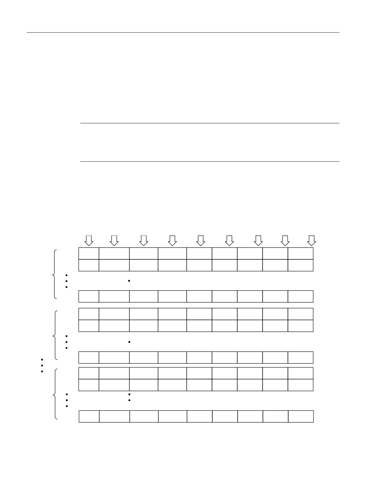
Maintenance
11.4 Message buffer
11.4
Message buffer
In addition to the fault buffer for F... faults and the alarm buffer for A... alarms (see the relevant
section in SINAMICS S120 Commissioning Manual), a special message buffer for C... safety
messages is available for Safety Integrated Extended/Advanced Functions.
The fault messages for the Safety Integrated Basic Functions are stored in the standard fault
buffer (see chapter "Buffer for faults and alarms" in the SINAMICS S120 Commissioning
Manual).
Note
Messages of the Basic and the Extended/Advanced Functions
Set parameter p3117 = 1 if you need to save both the Basic Functions messages and the
Extended/Advanced Functions messages in the standard fault buffer.
The message buffer for safety messages is similar to the fault buffer for fault messages. The
message buffer comprises the message code, message value, and message time (received,
resolved), the component number for identifying the affected SINAMICS component and
diagnostics attributes.
0HVVDJH
0HVVDJH WLPH
0HVVDJH
0HVVDJH
0HVVDJH WLPH
0HVVDJH WLPH
0HVVDJH
6, FRPSRQHQW 6, GLDJQRVWLFV
FRGH
UHFHLYHG LQ
YDOXH
YDOXH IRU IORDW
UHFHLYHG LQ
UHVROYHG
WLPH
QXPEHU
DWWULEXWH
PV
YDOXHV
GD\V
LQ PV
UHVROYHG
LQGD\V
0HVVDJH
U
> @
U
> @
U
> @
U
> @
U
> @
U
> @
U
> @
U
> @
U
> @
0HVVDJH
U
> @
U
> @
U
> @
U
> @
U
> @
U
> @
U
> @
U
> @
U
> @
&XUUHQW
PHVVDJH
FDVH
0HVVDJH
U
> @
U
> @
U
> @
U
> @
U
> @
U
> @
U
> @
U
> @
U
> @
0HVVDJH
U
> @
U
> @
U
> @
U
> @
U
> @
U
> @
U
> @
U
> @
U
> @
0HVVDJH
U
> @
U
> @
U
> @
U
> @
U
> @
U
> @
U
> @
U
> @
U
> @
$FNQRZ
OHGJHG
PHVVDJH
FDVH
0HVVDJH
U
>
@
U
>
@
U
>
@
U
>
@
U
>
@
U
>
@
U
>
@
U
>
@
U
>
@
0HVVDJH
U
>
@
U
>
@
U
>
@
U
>
@
U
>
@
U
>
@
U
>
@
U
>
@
U
>
@
0HVVDJH
U
>
@
U
>
@
U
>
@
U
>
@
U
>
@
U
>
@
U
>
@
U
>
@
U
>
@
$FNQRZ
OHGJHG
PHVVDJH
FDVH
>ROGHVW@
0HVVDJH
U
>
@
U
>
@
U
>
@
U
>
@
U
>
@
U
>
@
U
>
@
U
>
@
U
>
@
Figure 11-1
Structure of the message buffer
Safety Integrated
402
Function Manual, 06/2020, 6SL3097-5AR00-0BP3
Maintenance
11.4 Message buffer
When a safety message is present, bit r2139.5 is set to 1 ("safety message active"). The entry
in the message buffer is delayed. For this reason, the message buffer should not be read until
a change in the buffer (r9744) has been detected after "Safety message present" is output.
The messages must be acknowledged via a failsafe input F-DI of the TM54F/CU310-2 or via
PROFIsafe.
Properties of the safety message buffer:
● The entries appear in the buffer according to the time at which they occurred.
● If a new message case occurs, the message buffer is reorganized accordingly. The history
is recorded in the "Acknowledged message case" 1 to 7.
● If the cause of at least one message in "Current message case" is rectified and
acknowledged, the message buffer is reorganized accordingly. Messages that have not
been rectified remain in "Current message case".
● If "Current message case" contains 8 messages and a new message for the current
message case is output, the message in the current message case parameters is
overwritten with the new message in index 7.
● r9744 is incremented each time the message buffer changes.
● A message value (r9749, r9753) can be output for a message. The message value is used
to diagnose the message more accurately (refer to the message description for more
details).
Deleting the message buffer:
The message buffer can be deleted as follows: p9752 = 0. Parameter p9752 (SI message
cases, counter) is also reset to 0 at POWER ON. This also clears the fault memory.
Overview of important parameters (see SINAMICS S120/S150 List Manual)
● r2139.0...15 CO/BO: Status word, faults/alarms 1
● r9744
SI message buffer changes, counter
● r9745[0...63]
SI component
● r9747[0...63]
SI message code
● r9748[0...63]
SI message time received in milliseconds
● r9749[0...63]
SI message value
● r9750[0...63]
SI diagnostic attributes
● p9752
SI message cases, counter
● r9753[0...63]
SI message value for float values
● r9754[0...63]
SI message time received in days
● r9755[0...63]
SI message time removed in milliseconds
● r9756[0...63]
SI message time removed in days
Safety Integrated
Function Manual, 06/2020, 6SL3097-5AR00-0BP3
403
Maintenance
11.4 Message buffer
Safety Integrated
404
Function Manual, 06/2020, 6SL3097-5AR00-0BP3
Appendix
A
A.1
Modules available in Startdrive
A list of the hardware and functions of the SINAMICS S120, which are supported by Startdrive
V15, are provided in the Service and Support Portal at the following link (https://
support.industry.siemens.com/cs/ww/en/view/109761180).
The following new functions are available with Startdrive V16: Link (https://
support.industry.siemens.com/cs/ww/en/view/109771625)
Safety Integrated
Function Manual, 06/2020, 6SL3097-5AR00-0BP3
405
Appendix
A.2 List of abbreviations
A.2
List of abbreviations
Note
The following list of abbreviations includes all abbreviations and their meanings used in the
entire SINAMICS family of drives.
A
Abbreviation
Derivation of abbreviation
Meaning
A…
Alarm
Warning
AC
Alternating Current
Alternating current
ADC
Analog Digital Converter
Analog digital converter
AI
Analog Input
Analog input
AIM
Active Interface Module
Active Interface Module
ALM
Active Line Module
Active Line Module
AO
Analog Output
Analog output
AOP
Advanced Operator Panel
Advanced Operator Panel
APC
Advanced Positioning Control
Advanced Positioning Control
AR
Automatic Restart
Automatic restart
ASC
Armature Short-Circuit
Armature short-circuit
ASCII
American Standard Code for Information
American coding standard for the exchange of in-
Interchange
formation
AS-i
AS-Interface (Actuator Sensor Interface)
AS-Interface (open bus system in automation tech-
nology)
ASM
Asynchronmotor
Induction motor
AVS
Active Vibration Suppression
Active load vibration damping
AWG
American Wire Gauge
American Wire Gauge (Standard for cross-sections
of cables)
B
Abbreviation
Derivation of abbreviation
Meaning
BB
Betriebsbedingung
Operation condition
BERO
-
Contactless proximity switch
BI
Binector Input
Binector input
BIA
Berufsgenossenschaftliches Institut für
BG Institute for Occupational Safety and Health
Arbeitssicherheit
BICO
Binector Connector Technology
Binector connector technology
BLM
Basic Line Module
Basic Line Module
BO
Binector Output
Binector output
BOP
Basic Operator Panel
Basic operator panel
Safety Integrated
406
Function Manual, 06/2020, 6SL3097-5AR00-0BP3
Appendix
A.2 List of abbreviations
C
Abbreviation
Derivation of abbreviation
Meaning
C
Capacitance
Capacitance
C…
-
Safety message
CAN
Controller Area Network
Serial bus system
CBC
Communication Board CAN
Communication Board CAN
CBE
Communication Board Ethernet
PROFINET communication module (Ethernet)
CD
Compact Disc
Compact disc
CDS
Command Data Set
Command data set
CF Card
CompactFlash Card
CompactFlash card
CI
Connector Input
Connector input
CLC
Clearance Control
Clearance control
CNC
Computerized Numerical Control
Computer-supported numerical control
CO
Connector Output
Connector output
CO/BO
Connector Output/Binector Output
Connector/binector output
COB-ID
CAN Object-Identification
CAN Object Identification
CoL
Certificate of License
Certificate of License
COM
Common contact of a change-over relay
Center contact of a change-over contact
COMM
Commissioning
Commissioning
CP
Communication Processor
Communications processor
CPU
Central Processing Unit
Central processing unit
CRC
Cyclic Redundancy Check
Cyclic redundancy check
CSM
Control Supply Module
Control Supply Module
CU
Control Unit
Control Unit
CUA
Control Unit Adapter
Control Unit Adapter
CUD
Control Unit DC
Control Unit DC
D
Abbreviation
Derivation of abbreviation
Meaning
DAC
Digital Analog Converter
Digital analog converter
DC
Direct Current
Direct current
DCB
Drive Control Block
Drive Control Block
DCBRK
DC Brake
DC braking
DCC
Drive Control Chart
Drive Control Chart
DCN
Direct Current Negative
Direct current negative
DCP
Direct Current Positive
Direct current positive
DDC
Dynamic Drive Control
Dynamic Drive Control
DDS
Drive Data Set
Drive Data Set
DHCP
Dynamic Host Configuration Protocol
Dynamic Host Configuration Protocol (Communica-
tion protocol)
DI
Digital Input
Digital input
DI/DO
Digital Input/Digital Output
Digital input/output, bidirectional
Safety Integrated
Function Manual, 06/2020, 6SL3097-5AR00-0BP3
407
Appendix
A.2 List of abbreviations
Abbreviation
Derivation of abbreviation
Meaning
DIN
Deutsches Institut für Normung
Deutsches Institut für Normung (German Institute
for Standardization)
DMC
DRIVE-CLiQ Hub Module Cabinet
DRIVE-CLiQ Hub Module Cabinet
DME
DRIVE-CLiQ Hub Module External
DRIVE-CLiQ Hub Module External
DMM
Double Motor Module
Double Motor Module
DO
Digital Output
Digital output
DO
Drive Object
Drive object
DP
Decentralized Peripherals
Distributed I/O
DPRAM
Dual Ported Random Access Memory
Dual-Port Random Access Memory
DQ
DRIVE-CLiQ
DRIVE-CLiQ
DRAM
Dynamic Random Access Memory
Dynamic Random Access Memory
DRIVE-CLiQ
Drive Component Link with IQ
Drive Component Link with IQ
DSC
Dynamic Servo Control
Dynamic Servo Control
DSM
Doppelsubmodul
Double submodule
DTC
Digital Time Clock
Timer
E
Abbreviation
Derivation of abbreviation
Meaning
EASC
External Armature Short-Circuit
External armature short-circuit
EDS
Encoder Data Set
Encoder data set
EEPROM
Electrically Erasable Programmable Read-Only
Electrically Erasable Programmable Read-Only
Memory
Memory
EGB
Elektrostatisch gefährdete Baugruppen
Electrostatic sensitive devices
EIP
EtherNet/IP
EtherNet Industrial Protocol (real-time Ethernet)
ELCB
Earth Leakage Circuit Breaker
Residual current operated circuit breaker
ELP
Earth Leakage Protection
Ground-fault monitoring
EMC
Electromagnetic Compatibility
Electromagnetic compatibility
EMF
Electromotive Force
Electromotive force
EMK
Elektromotorische Kraft
Electromotive force
EMV
Elektromagnetische Verträglichkeit
Electromagnetic compatibility
EN
Europäische Norm
European standard
EnDat
Encoder-Data-Interface
Encoder interface
EP
Enable Pulses
Pulse enable
EPOS
Einfachpositionierer
Basic positioner
ES
Engineering System
Engineering system
ESB
Ersatzschaltbild
Equivalent circuit diagram
ESD
Electrostatic Sensitive Devices
Electrostatic sensitive devices
ESM
Essential Service Mode
Essential service mode
ESR
Extended Stop and Retract
Extended stop and retract
Safety Integrated
408
Function Manual, 06/2020, 6SL3097-5AR00-0BP3
Appendix
A.2 List of abbreviations
F
Abbreviation
Derivation of abbreviation
Meaning
F…
Fault
Fault
FAQ
Frequently Asked Questions
Frequently Asked Questions
FBLOCKS
Free Blocks
Free function blocks
FCC
Function Control Chart
Function control chart
FCC
Flux Current Control
Flux current control
FD
Function Diagram
Function diagram
F-DI
Failsafe Digital Input
Fail-safe digital input
F-DO
Failsafe Digital Output
Fail-safe digital output
FEPROM
Flash-EPROM
Non-volatile write and read memory
FG
Function Generator
Function generator
FI
-
Fault current
FOC
Fiber-Optic Cable
Fiber-optic cable
FP
Funktionsplan
Function diagram
FPGA
Field Programmable Gate Array
Field Programmable Gate Array
F-PLC
Fail-safe PLC
Fail-safe PLC
FW
Firmware
Firmware
G
Abbreviation
Derivation of abbreviation
Meaning
GB
Gigabyte
Gigabyte
GC
Global Control
Global control telegram (broadcast telegram)
GND
Ground
Reference potential for all signal and operating vol-
tages, usually defined as 0 V (also referred to as M)
GSD
Gerätestammdaten
Device master data: Describe the features of a
PROFIBUS slave
GSV
Gate Supply Voltage
Gate supply voltage
GUID
Globally Unique Identifier
Globally Unique Identifier
H
Abbreviation
Derivation of abbreviation
Meaning
HF
High frequency
High frequency
HFD
Hochfrequenzdrossel
Radio frequency reactor
HLA
Hydraulic Linear Actuator
Hydraulic linear actuator
HLG
Hochlaufgeber
Ramp-function generator
HM
Hydraulic Module
Hydraulic Module
HMI
Human Machine Interface
Human Machine Interface
HTL
High-Threshold Logic
Logic with high interference threshold
HTTP
Hypertext Transfer Protocol
Hypertext Transfer Protocol (communication proto-
col)
Safety Integrated
Function Manual, 06/2020, 6SL3097-5AR00-0BP3
409
Appendix
A.2 List of abbreviations
Abbreviation
Derivation of abbreviation
Meaning
HTTP
Hypertext Transfer Protocol Secure
Hypertext Transfer Protocol Secure (communica-
tion protocol)
HW
Hardware
Hardware
I
Abbreviation
Derivation of abbreviation
Meaning
i. V.
In Vorbereitung
Under development: This property is currently not
available
I/O
Input/Output
Input/output
I2C
Inter-Integrated Circuit
Internal serial data bus
IASC
Internal Armature Short-Circuit
Internal armature short-circuit
IBN
Inbetriebnahme
Commissioning
ID
Identifier
Identification
IE
Industrial Ethernet
Industrial Ethernet
IEC
International Electrotechnical Commission
International Electrotechnical Commission
IF
Interface
Interface
IGBT
Insulated Gate Bipolar Transistor
Insulated gate bipolar transistor
IGCT
Integrated Gate-Controlled Thyristor
Semiconductor power switch with integrated control
electrode
IL
Impulslöschung
Pulse suppression
IP
Internet Protocol
Internet Protocol
IPO
Interpolator
Interpolator
ISO
Internationale Organisation für Normung
International Standards Organization
IT
Isolé Terre
Non-grounded three-phase line supply
IVP
Internal Voltage Protection
Internal voltage protection
J
Abbreviation
Derivation of abbreviation
Meaning
JOG
Jogging
Jogging
K
Abbreviation
Derivation of abbreviation
Meaning
KDV
Kreuzweiser Datenvergleich
Data cross-check
KHP
Know-how protection
Know-how protection
KIP
Kinetische Pufferung
Kinetic buffering
Kp
-
Proportional gain
KTY84-130
-
Temperature sensor
Safety Integrated
410
Function Manual, 06/2020, 6SL3097-5AR00-0BP3
Appendix
A.2 List of abbreviations
L
Abbreviation
Derivation of abbreviation
Meaning
L
L
-
Symbol for inductance
LED
Light Emitting Diode
Light emitting diode
LIN
Linearmotor
Linear motor
LR
Lageregler
Position controller
LSB
Least Significant Bit
Least significant bit
LSC
Line-Side Converter
Line-side converter
LSS
Line-Side Switch
Line-side switch
LU
Length Unit
Length unit
LWL
Lichtwellenleiter
Fiber-optic cable
M
Abbreviation
Derivation of abbreviation
Meaning
M
-
Symbol for torque
M
Masse
Reference potential for all signal and operating vol-
tages, usually defined as 0 V (also referred to as
GND)
MB
Megabyte
Megabyte
MCC
Motion Control Chart
Motion Control Chart
MDI
Manual Data Input
Manual data input
MDS
Motor Data Set
Motor data set
MLFB
Maschinenlesbare Fabrikatebezeichnung
Machine-readable product code
MM
Motor Module
Motor Module
MMC
Man-Machine Communication
Man-machine communication
MMC
Micro Memory Card
Micro memory card
MRCD
Modular Residual Current protection Device
Modular Residual Current protection Device
MSB
Most Significant Bit
Most significant bit
MSC
Motor-Side Converter
Motor-side converter
MSCY_C1
Master Slave Cycle Class 1
Cyclic communication between master (class 1)
and slave
MSR
Motorstromrichter
Motor-side converter
MT
Messtaster
Probe
N
Abbreviation
Derivation of abbreviation
Meaning
N. C.
Not Connected
Not connected
N…
No Report
No report or internal message
NAMUR
Interessengemeinschaft Automatisierungstechnik
User association of automation technology in the
der Prozessindustrie
process industry
Safety Integrated
Function Manual, 06/2020, 6SL3097-5AR00-0BP3
411
Appendix
A.2 List of abbreviations
Abbreviation
Derivation of abbreviation
Meaning
NC
Normally Closed (contact)
NC contact
NC
Numerical Control
Numerical control
NEMA
National Electrical Manufacturers Association
Standardization association in USA (United States
of America)
NM
Nullmarke
Zero mark
NO
Normally Open (contact)
NO contact
NSR
Netzstromrichter
Line-side converter
NTP
Network Time Protocol
Standard for synchronization of the time of day
NVRAM
Non-Volatile Random Access Memory
Non-volatile read/write memory
O
Abbreviation
Derivation of abbreviation
Meaning
OA
Open Architecture
Software component which provides additional
functions for the SINAMICS drive system
OAIF
Open Architecture Interface
Version of the SINAMICS firmware as of which the
OA application can be used
OASP
Open Architecture Support Package
Expands the commissioning tool by the correspond-
ing OA application
OC
Operating Condition
Operation condition
OCC
One Cable Connection
One-cable technology
OEM
Original Equipment Manufacturer
Original equipment manufacturer
OLP
Optical Link Plug
Bus connector for fiber-optic cable
OMI
Option Module Interface
Option Module Interface
P
Abbreviation
Derivation of abbreviation
Meaning
p…
-
Adjustable parameters
P1
Processor 1
CPU 1
P2
Processor 2
CPU 2
PB
PROFIBUS
PROFIBUS
PcCtrl
PC Control
Master control
PD
PROFIdrive
PROFIdrive
PDC
Precision Drive Control
Precision Drive Control
PDS
Power unit Data Set
Power unit data set
PDS
Power Drive System
Drive system
PE
Protective Earth
Protective ground
PELV
Protective Extra Low Voltage
Safety extra-low voltage
PFH
Probability of dangerous failure per hour
Probability of dangerous failure per hour
PG
Programmiergerät
Programming device
PI
Proportional Integral
Proportional integral
PID
Proportional Integral Differential
Proportional integral differential
Safety Integrated
412
Function Manual, 06/2020, 6SL3097-5AR00-0BP3
Appendix
A.2 List of abbreviations
Abbreviation
Derivation of abbreviation
Meaning
PLC
Programmable Logical Controller
Programmable logic controller
PLL
Phase-Locked Loop
Phase-locked loop
PM
Power Module
Power Module
PMI
Power Module Interface
Power Module Interface
PMSM
Permanent-magnet synchronous motor
Permanent-magnet synchronous motor
PN
PROFINET
PROFINET
PNO
PROFIBUS Nutzerorganisation
PROFIBUS user organization
PPI
Point to Point Interface
Point-to-point interface
PRBS
Pseudo Random Binary Signal
White noise
PROFIBUS
Process Field Bus
Serial data bus
PS
Power Supply
Power supply
PSA
Power Stack Adapter
Power Stack Adapter
PT1000
-
Temperature sensor
PTC
Positive Temperature Coefficient
Positive temperature coefficient
PTP
Point To Point
Point-to-point
PWM
Pulse Width Modulation
Pulse width modulation
PZD
Prozessdaten
Process data
Q
Abbreviation
Derivation of abbreviation
Meaning
No entries
R
Abbreviation
Derivation of abbreviation
Meaning
r…
-
Display parameters (read-only)
RAM
Random Access Memory
Memory for reading and writing
RCCB
Residual Current Circuit Breaker
Residual current operated circuit breaker
RCD
Residual Current Device
Residual current device
RCM
Residual Current Monitor
Residual current monitor
REL
Reluctance motor textile
Reluctance motor textile
RESM
Reluctance synchronous motor
Synchronous reluctance motor
RFG
Ramp-Function Generator
Ramp-function generator
RJ45
Registered Jack 45
Term for an 8-pin socket system for data transmis-
sion with shielded or non-shielded multi-wire copper
cables
RKA
Rückkühlanlage
Cooling unit
RLM
Renewable Line Module
Renewable Line Module
RO
Read Only
Read only
ROM
Read-Only Memory
Read-only memory
RPDO
Receive Process Data Object
Receive Process Data Object
Safety Integrated
Function Manual, 06/2020, 6SL3097-5AR00-0BP3
413
Appendix
A.2 List of abbreviations
Abbreviation
Derivation of abbreviation
Meaning
RS232
Recommended Standard 232
Interface standard for cable-connected serial data
transmission between a sender and receiver (also
known as EIA232)
RS485
Recommended Standard 485
Interface standard for a cable-connected differen-
tial, parallel, and/or serial bus system (data trans-
mission between a number of senders and receiv-
ers, also known as EIA485)
RTC
Real Time Clock
Real-time clock
RZA
Raumzeigerapproximation
Space-vector approximation
S
Abbreviation
Derivation of abbreviation
Meaning
S1
-
Continuous operation
S3
-
Intermittent duty
SAM
Safe Acceleration Monitor
Safe acceleration monitoring
SBC
Safe Brake Control
Safe brake control
SBH
Sicherer Betriebshalt
Safe operating stop
SBR
Safe Brake Ramp
Safe brake ramp monitoring
SBT
Safe Brake Test
Safe brake test
SCA
Safe Cam
Safe cam
SCC
Safety Control Channel
Safety Control Channel
SCSE
Single Channel Safety Encoder
Single-channel safety encoder
SD Card
SecureDigital Card
Secure digital memory card
SDC
Standard Drive Control
Standard Drive Control
SDI
Safe Direction
Safe motion direction
SE
Sicherer Software-Endschalter
Safe software limit switch
SESM
Separately-excited synchronous motor
Separately excited synchronous motor
SG
Sicher reduzierte Geschwindigkeit
Safely limited speed
SGA
Sicherheitsgerichteter Ausgang
Safety-related output
SGE
Sicherheitsgerichteter Eingang
Safety-related input
SH
Sicherer Halt
Safe stop
SI
Safety Integrated
Safety Integrated
SIC
Safety Info Channel
Safety Info Channel
SIL
Safety Integrity Level
Safety Integrity Level
SITOP
-
Siemens power supply system
SLA
Safely-Limited Acceleration
Safely limited acceleration
SLM
Smart Line Module
Smart Line Module
SLP
Safely-Limited Position
Safely Limited Position
SLS
Safely-Limited Speed
Safely limited speed
SLVC
Sensorless Vector Control
Sensorless vector control
SM
Sensor Module
Sensor Module
SMC
Sensor Module Cabinet
Sensor Module Cabinet
Safety Integrated
414
Function Manual, 06/2020, 6SL3097-5AR00-0BP3
Appendix
A.2 List of abbreviations
Abbreviation
Derivation of abbreviation
Meaning
SME
Sensor Module External
Sensor Module External
SMI
SINAMICS Sensor Module Integrated
SINAMICS Sensor Module Integrated
SMM
Single Motor Module
Single Motor Module
SN
Sicherer Software-Nocken
Safe software cam
SOS
Safe Operating Stop
Safe operating stop
SP
Service Pack
Service pack
SP
Safe Position
Safe position
SPC
Setpoint Channel
Setpoint channel
SPI
Serial Peripheral Interface
Serial peripheral interface
SPS
Speicherprogrammierbare Steuerung
Programmable logic controller
SS1
Safe Stop 1
Safe Stop 1 (time-monitored, ramp-monitored)
SS1E
Safe Stop 1 External
Safe Stop 1 with external stop
SS2
Safe Stop 2
Safe Stop 2
SS2E
Safe Stop 2 External
Safe Stop 2 with external stop
SSI
Synchronous Serial Interface
Synchronous serial interface
SSL
Secure Sockets Layer
Encryption protocol for secure data transfer (new
TLS)
SSM
Safe Speed Monitor
Safe feedback from speed monitor
SSP
SINAMICS Support Package
SINAMICS support package
STO
Safe Torque Off
Safe torque off
STW
Steuerwort
Control word
T
Abbreviation
Derivation of abbreviation
Meaning
TB
Terminal Board
Terminal Board
TEC
Technology Extension
Software component which is installed as an addi-
tional technology package and which expands the
functionality of SINAMICS (previously OA applica-
tion)
TIA
Totally Integrated Automation
Totally Integrated Automation
TLS
Transport Layer Security
Encryption protocol for secure data transfer (previ-
ously SSL)
TM
Terminal Module
Terminal Module
TN
Terre Neutre
Grounded three-phase line supply
Tn
-
Integral time
TPDO
Transmit Process Data Object
Transmit Process Data Object
TSN
Time-Sensitive Networking
Time-Sensitive Networking
TT
Terre Terre
Grounded three-phase line supply
TTL
Transistor-Transistor-Logic
Transistor-transistor logic
Tv
-
Rate time
Safety Integrated
Function Manual, 06/2020, 6SL3097-5AR00-0BP3
415
Appendix
A.2 List of abbreviations
U
Abbreviation
Derivation of abbreviation
Meaning
UL
Underwriters Laboratories Inc.
Underwriters Laboratories Inc.
UPS
Uninterruptible Power Supply
Uninterruptible power supply
USV
Unterbrechungsfreie Stromversorgung
Uninterruptible power supply
UTC
Universal Time Coordinated
Universal time coordinated
V
Abbreviation
Derivation of abbreviation
Meaning
VC
Vector Control
Vector control
Vdc
-
DC link voltage
VdcN
-
Partial DC link voltage negative
VdcP
-
Partial DC link voltage positive
VDE
Verband der Elektrotechnik, Elektronik und Informa-
Association of Electrical Engineering, Electronics
tionstechnik
and Information Technology
VDI
Verein Deutscher Ingenieure
Verein Deutscher Ingenieure [Association of Ger-
man Engineers]
VPM
Voltage Protection Module
Voltage Protection Module
Vpp
Volt peak to peak
Volt peak to peak
VSM
Voltage Sensing Module
Voltage Sensing Module
W
Abbreviation
Derivation of abbreviation
Meaning
WEA
Wiedereinschaltautomatik
Automatic restart
WZM
Werkzeugmaschine
Machine tool
X
Abbreviation
Derivation of abbreviation
Meaning
XML
Extensible Markup Language
Extensible markup language (standard language
for Web publishing and document management)
Y
Abbreviation
Derivation of abbreviation
Meaning
No entries
Safety Integrated
416
Function Manual, 06/2020, 6SL3097-5AR00-0BP3
Appendix
A.2 List of abbreviations
Z
Abbreviation
Derivation of abbreviation
Meaning
ZK
Zwischenkreis
DC link
ZM
Zero Mark
Zero mark
ZSW
Zustandswort
Status word
Safety Integrated
Function Manual, 06/2020, 6SL3097-5AR00-0BP3
417
Appendix
A.3 Documentation overview
A.3
Documentation overview
*HQHUDO GRFXPHQWDWLRQ FDWDORJV
6,1$0,&6
*
'
&RQYHUWHU &KDVVLV 8QLWV
N: XS WR N:
*
'
6,1$0,&6 &RQYHUWHUV IRU 6LQJOH $[LV 'ULYHV DQG 6,027,&6 0RWRUV
*
*
'
&RQYHUWHU &KDVVLV 8QLWV
&RQYHUWHU &DELQHW 8QLWV
6
6
'
6,1$0,&6 6
&KDVVLV 8QLWV DQG &DELQHW 0RGXOHV
6,1$0,&6 6
&RQYHUWHU &DELQHW 8QLWV
6
'
6,1$0,&6 6
DQG 6,027,&6
0DQXIDFWXUHU VHUYLFH GRFXPHQWDWLRQ
6,1$0,&6
*
*HWWLQJ 6WDUWHG
2SHUDWLQJ ,QVWUXFWLRQV
/LVW 0DQXDOV
*
*HWWLQJ 6WDUWHG
2SHUDWLQJ ,QVWUXFWLRQV
,QVWDOODWLRQ 0DQXDOV
)XQFWLRQ 0DQXDO 6DIHW\ ,QWHJUDWHG
/LVW 0DQXDOV
*
2SHUDWLQJ ,QVWUXFWLRQV
/LVW 0DQXDO
*
2SHUDWLQJ ,QVWUXFWLRQV
/LVW 0DQXDO
*0
2SHUDWLQJ ,QVWUXFWLRQV
60
60
/LVW 0DQXDOV
*/
6/
6
(TXLSPHQW 0DQXDO
*HWWLQJ 6WDUWHG
)XQFWLRQ 0DQXDO
/LVW 0DQXDO
6
*HWWLQJ 6WDUWHG
&RPPLVVLRQLQJ 0DQXDO
)XQFWLRQ 0DQXDO 'ULYH )XQFWLRQV
)XQFWLRQ 0DQXDO &RPPXQLFDWLRQ IURP ILUPZDUH 9
)XQFWLRQ 0DQXDO 6DIHW\ ,QWHJUDWHG
)XQFWLRQ 0DQXDO '&&
/LVW 0DQXDO
(TXLSPHQW 0DQXDO IRU &RQWURO 8QLWV DQG 6XSSOHPHQWDU\ 6\VWHP &RPSRQHQWV
(TXLSPHQW 0DQXDO IRU %RRNVL]H 3RZHU 8QLWV
(TXLSPHQW 0DQXDO IRU $LU &RROHG &KDVVLV 3RZHU 8QLWV
(TXLSPHQW 0DQXDO IRU /LTXLG &RROHG &KDVVLV 3RZHU 8QLWV
(TXLSPHQW 0DQXDO IRU :DWHU &RROHG &KDVVLV 3RZHU 8QLWV IRU &RPPRQ &RROLQJ &LUFXLWV
(TXLSPHQW 0DQXDO &RPEL
(TXLSPHQW 0DQXDO IRU &DELQHW 0RGXOHV
(TXLSPHQW 0DQXDO IRU $& 'ULYHV
6,1$0,&6 6
0 (TXLSPHQW 0DQXDO 'LVWULEXWHG 'ULYH 7HFKQRORJ\
6,1$0,&6 +/$ 6\VWHP 0DQXDO +\GUDXOLF 'ULYH
6
2SHUDWLQJ ,QVWUXFWLRQV
/LVW 0DQXDO
6
6,1$0,&6 6
2SHUDWLQJ ,QVWUXFWLRQV
0RWRUV
&RQILJXUDWLRQ 0DQXDOV 0RWRUV
*HQHUDO
&RQILJXUDWLRQ 0DQXDO (0& ,QVWDOODWLRQ *XLGHOLQH
Safety Integrated
418
Function Manual, 06/2020, 6SL3097-5AR00-0BP3
Appendix
A.4 Change history
A.4
Change history
Significant changes with respect to the Manual, Edition 11/2017
New functions in Firmware V5.2
See Chapter
Acceptance test wizard in Startdrive
Acceptance test with Startdrive (Page 343)
Safe Stop 2 Extended Stop and Retract
Safe Stop 2 Extended Stop and Retract (SS2ESR)
(Page 115)
Commissioning with Startdrive
● Taken into account at many locations in the manual.
● Modules available in Startdrive (Page 405)
Revised/supplementary descriptions
See Chapter
Acceptance test suggestions removed
Former Chapter A.4
Note
An overview of the availability of hardware components and software functions is provided in
the appendix of the following literature:
● SINAMICS S120 Function Manual Drive Functions
Safety Integrated
Function Manual, 06/2020, 6SL3097-5AR00-0BP3
419
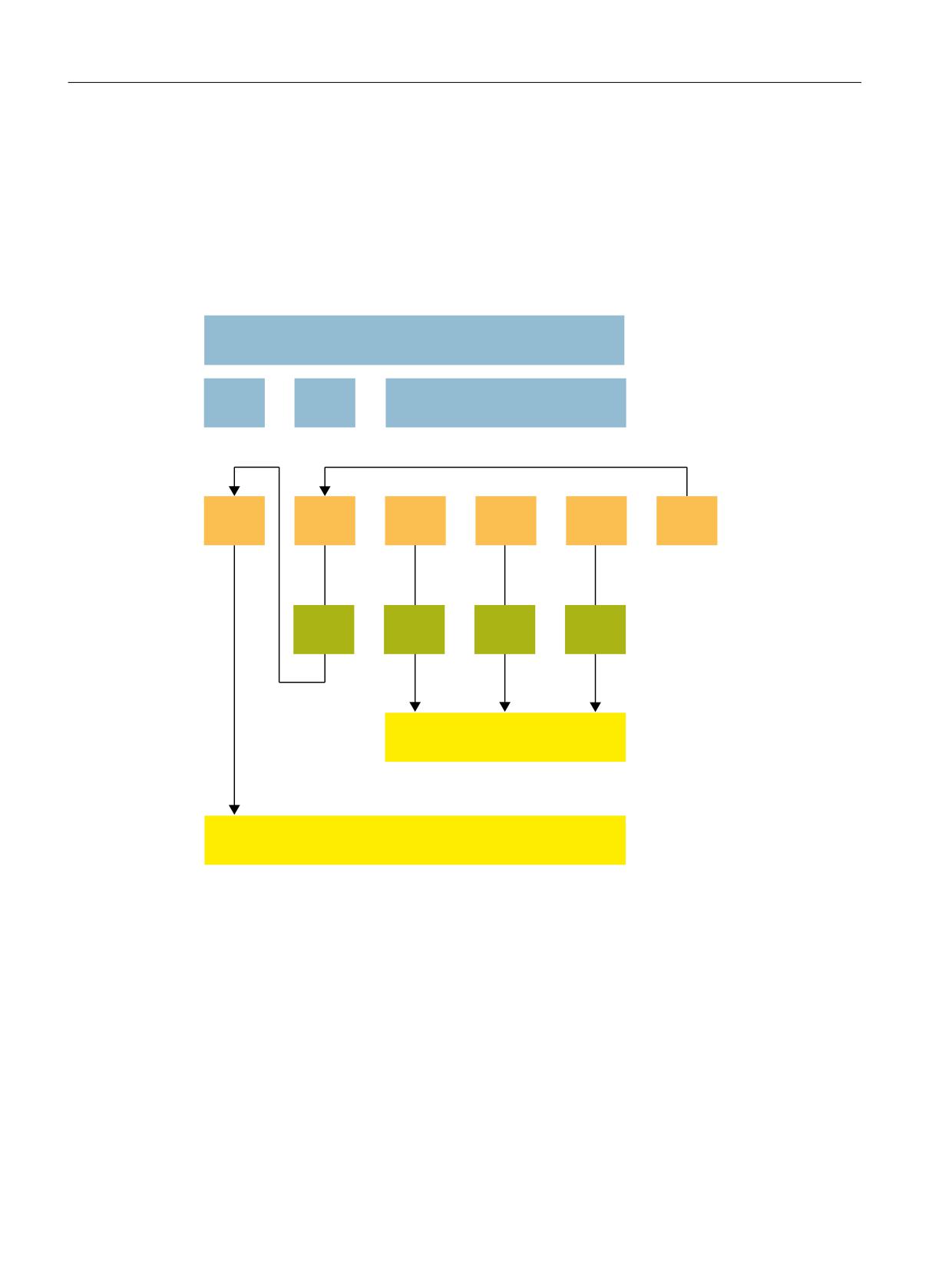
Appendix
A.5 Stop versions
A.5
Stop versions
Safe stops are used to stop a drive and bring it to a standstill. The type of stop response that
occurs in the event of faults/errors can either be permanently specified by the system or
configured by the machine manufacturer.
In this way, the shutdown of the machine can be optimally adapted to the respective situation.
In the following list, STOP B can be compared to an SS1 and STOP C to an SS2.
6WRS FDWHJRU\ DFF WR (1
3DUW
6723
$
6723 %
6723 &
6723 '
6723 (
6723 )
:LWK
QVHW
QVHW
UHIHUHQFH
5HWUDFWLRQ
WR SDWK
6DIH 2SHUDWLQJ 6WRS 626
'ULYH XQGHU FORVHG ORRS FRQWURO
6DIH 7RUTXH 2II 672
3XOVH VXSSUHVVLRQ
Figure A-1
Overview of the stop versions
STOP A
With STOP A (corresponds to a Stop Category 0 according to EN 60204-1, without electrical
isolation), the drive is switched directly to zero torque via the STO function. A drive that is still
running coasts to a standstill. A drive at standstill cannot be started again accidentally.
Application:
● E.g. for safety faults
Safety Integrated
420
Function Manual, 06/2020, 6SL3097-5AR00-0BP3
Appendix
A.5 Stop versions
STOP B
The drive is braked at the current limit under speed control and brought to a safe standstill
(SOS) (corresponds to a Stop Category 1 according to EN 60204-1, without electrical isolation).
Application
● E.g. when SOS responds
STOP C
The drive is braked at the current limit under speed control and brought to a safe operating stop
(corresponds to a Stop Category 2 according to EN 60204-1).
A STOP C followed by a STOP A is normally selected in the case of an emergency stop
because this is the quickest way of stopping a drive.
Application:
● Operator protection
STOP D
The drives are braked together in a path-related (interpolatory) way on the contour and brought
to a safe operating stop (SOS).
Application:
● Protection for tool and workpiece (machine protection)
STOP E
The drives are braked together, including a jerk motion during which the tool and workpiece are
separated from one another, path-related and brought to a safe operating stop.
Application:
● Machine protection
STOP F
The STOP F is permanently assigned to the result and data cross-check and cannot be
changed by the user.
If a discrepancy is found in the monitoring channels of Safety Integrated, a STOP F is triggered.
Depending on the parameter assignment, a STOP A or STOP B response is triggered.
Applications:
● Detection of errors during the crosswise data and result comparison
● Detection of communication errors between SINUMERIK and the drive
● Detection of encoder errors
Safety Integrated
Function Manual, 06/2020, 6SL3097-5AR00-0BP3
421