SINUMERIK 840D sl. Service - Safety Integrated. Manual (2020) - page 22
Description of Safety Integrated functions
5.3 Safety Integrated Advanced Functions
5.3.3.3
Function diagrams and parameters
Function diagrams (see SINAMICS S120/S150 List Manual)
●
2822
SI functions - SLP (Safely-Limited Position)
●
2840
SI functions - SI Motion drive-integrated control signals/status signals
●
2893
SI TM54F - Failsafe digital inputs (F-DI 0 ... F-DI 4)
●
2894
SI TM54F - Failsafe digital inputs (F-DI 5 ... F-DI 9)
●
2895
SI TM54F - Failsafe digital outputs (F-DO 0 ... 3),
digital inputs (DI 20 ... 23)
●
2905
SI TM54F - control interface (p9601.2 = 1 & p9601.3 = 0)
●
2906
SI TM54F - safe state selection
●
2907
SI TM54F assignment (F-DO0 ... F-DO3)
●
2870
SI functions - CU310-2 (F-DI 0 ... F-DI 2)
●
2873
SI functions CU310-2 failsafe digital output (F-DO 0)
●
2875
SI functions - CU310-2 control interface
●
2876
SI functions - CU310-2 safe state selection
●
2877
SI functions, CU310-2 assignment (F-DO 0)
Overview of important parameters (see SINAMICS S120/S150 List Manual)
● p9501
SI Motion enable safety functions (Control Unit)
● p9534[0...1]
SI Motion SLP (SE) upper limit values (Control Unit)
● p9535[0...1]
SI Motion SLP (SE) lower limit values (Control Unit)
● p9544
SI Motion actual value comparison tolerance (referencing) (CU)
● p9562[0...1]
SI Motion SLP (SE) stop response (Control Unit)
● p10009
SI Motion SLP retraction F-DI (CPU 1)
● p10032[0...3]
SI TM54F SLP input terminal (CPU 1)
● p10033[0...3]
SI TM54F SLP position range input terminal (CPU 1)
● p10039[0...3]
SI TM54F Safe State signal selection (CPU 1)
● p10109
SI Motion SLP retraction F-DI (CPU 2)
● p10132
SI Motion SLP input terminal (CPU 2)
● p10133
SI Motion SLP position range input terminal (CPU 2)
● p10139
SI Motion Safe State signal selection (CPU 2)
Safety Integrated
Function Manual, 06/2020, 6SL3097-5AR00-0BP3
187
Description of Safety Integrated functions
5.3 Safety Integrated Advanced Functions
5.3.4
Transferring safe position values (SP)
The function "Transfer safe position values (SP)" enables you to transfer a safe position (i.e.
absolute or relative position) to the higher-level controller via PROFIsafe. Transfer of the safe
relative position (Safe Position SP) can be used to calculate the safe speed in a higher-level
controller. Its use for safe position monitoring is only permissible if the reference to the absolute
position was established at the controller level. In this case, the "safely referenced" bit of
SINAMICS S120 (r9722.23) cannot be used.
Enabling the "Transfer safe position values" function
The following steps are required to enable the "Transfer safe position values" function:
● Enabling Safety Integrated Functions
- p9601 = 12 = C hex (≙ Extended Functions via PROFIsafe)
or
- p9601 = 13 = D hex (≙ Extended Functions via PROFIsafe and Basic Functions via
onboard terminals)
● Enable "Transfer the safe absolute position with the possibility of calculating the velocity by
the controller"
- Select one of the PROFIsafe telegrams 901 or 902 (p60022, p9611, p9811)
- p9501.2 = 1 (≙ enable absolute position)
- p9501.25 = 1 (≙ enable transfer of safe position via PROFIsafe)
Note
No actual value synchronization when SP is enabled
If the transfer safe position value function is used, it is not permissible to enable actual value
synchronization (p9501.3 = 1): In this case, the drive outputs fault F01688.
● Enable the "Transfer safe relative position" only to calculate the speed by the controller
- Select one of the PROFIsafe telegrams 901 or 902
- p9501.25 = 1
● After the enable, POWER ON the converter.
Safety Integrated
188
Function Manual, 06/2020, 6SL3097-5AR00-0BP3
Description of Safety Integrated functions
5.3 Safety Integrated Advanced Functions
Principle of operation
After parameter assignment, release and POWER ON, the function is automatically selected
and the values transferred. Please observe the following:
● Transfer of safe absolute position values
- If the transfer of the safe relative position has been enabled through p9501.25 = 1 and
p9501.2 = 0, the validity of the safe relative position is displayed by the set bit
S_ZSW2.22.
- If the transfer of the safe absolute position has been enabled using p9501.25 = 1 and
p9501.2 = 1, S_ZSW2.22 is only set when the drive has also been safely referenced.
● Transfer of safe relative position values (e.g. for calculating the velocity)
- Only S_ZSW2.22 (r9722.22, actual position value valid) must be set to calculate the
speed.
Setting the modulo value for rotary axes
● P9505 is used to define the modulo range of a safety rotary axis (p9502 = 1) when the
transfer of a safe absolute position (p9501.2 = 1 and p9501.25 = 1) is enabled.
Parameterizing the modulo value can result in a jump in the position actual value if the range
that can be represented overflows. p9505 must therefore only be parameterized in steps of
2n × 360° (n = 1, 2, 3, …). In all other cases, the converter issues alarm A01794. This alarm
can be hidden in the case that the possible jump in the position actual value can be tolerated
in the particular application - or this does not present a problem.
● The modulo function is deactivated if p9505 = 0. This parameter has no relevance for a
safety linear axis (p9502 = 0) or when the transfer of a safe relative position (p9501.2 = 0 and
p9501.25 = 1) is enabled.
● If SLP is also enabled (p9501.1 = 1), the modulo function must be deactivated (p9505 = 0).
Speed calculation
The control must calculate the speed from the position change:
● Pos diff = Pos new - Pos old
● Cycle diff = cycle counter new - cycle counter old
● Timediff = Cyclediff · Safetycycle
(If Cyclediff = 0, the speed that was last calculated must be used.)
● v = Pos diff/time diff
● Format v
Acceptance test
An acceptance test is not required for the "Transfer safe position values" function, but the
function that was implemented with the aid of SP must be accepted in the higher-level
controller.
Safety Integrated
Function Manual, 06/2020, 6SL3097-5AR00-0BP3
189

Description of Safety Integrated functions
5.3 Safety Integrated Advanced Functions
5.3.4.1
Ranges of values
Transfer formats and value range
●
32-bit
The values are transferred in telegram 902 as 32-bit values with the following value ranges:
Table 5-4
Value range and resolution (32 bits)
Linear axis
Rotary axis
Position values
±737280000
±737280000
Unit
1 μm
0.001 °
Comment
Monitoring ±737.280 m with an
≙ 2048 revolutions
accuracy of 1 μm
●
16-bit
To transfer the position values in telegram 901 in the 16-bit format, you must scale the
values using p9574. In this case, you must select the scaling factor so that the value of the
actual position value does not exceed the 16-bit format. If the actual position value exceeds
the range that can be displayed with 16 bits (±32767), a STOP F is initiated and message
C01711 is output with fault value 7001. Depending on the scaling factor, this means that
ranges with different sizes can be monitored with varying accuracy. Example:
- Scaling factor: 1000
- Unit: 1 μm (linear axis)
- Position value: ±32767 mm
It may therefore be precisely monitored in a range of ±32.767 m to an accuracy of 1 mm.
Note
Scaling to 16 bits
The scaling is performed by dividing the mean value of r9708[0] and r9708[1] with this
scaling factor.
Example: For a position of -29.999 mm signaled in r9708[0] and r9708[1] and a scaling
factor of p9574 = 1000, a numerical value of -29 is signaled to the controller.
Value range r9708
The diagnostics information in parameter r9708 is displayed with the following properties:
Table 5-5
Value range and resolution (32 bits)
Linear axis
Rotary axis
Position values
±737280000
±737280000
Unit
1 μm
0.001 °
Comment
Monitoring ±737.280 m with an
≙ 2048 revolutions
accuracy of 1 μm
Safety Integrated
190
Function Manual, 06/2020, 6SL3097-5AR00-0BP3
Description of Safety Integrated functions
5.3 Safety Integrated Advanced Functions
What is shown in parameter r9713 is identical to the values of r9708; however, in SINAMICS-
internal calculation units.
5.3.4.2
Synchronous transfer of safe position values
For axes that have to transfer their position values synchronously due to their application,
proceed as follows:
Note
Only available for CU320-2
This feature is not available for CU310-2.
Selection and enabling
1. For all axes that must transfer their position synchronously at the same time, parameterize
the following:
- Activating synchronous position transmission: p9501.29 = 1
- Enabling SP via PROFIsafe: p9501.25 = 1
2. Set the same fieldbus cycle (DP/PN cycle) and the same SI Motion monitoring cycle (tSI) for
all relevant axes.
The DP/PN cycle must be an even multiple of the SI Motion monitoring cycle. Example for
setting the cycles:
Current controller cycle
= 0.125 ms
(p115[0])
SI Motion actual value acquis- = 1.0 ms
ition cycle (p9511)
SI Motion monitoring cycle
= 2.0 ms
(p9500)
Fieldbus-cycle (DP/PN cycle) = 4.0 ms
● Activate clock synchronized PROFIdrive communication for all affected axes.
Note
Acceptance test required
If you change the fieldbus cycle after safety acceptance has already taken place, you must
carry out a new safety acceptance test.
Activation
The synchronous transmission of safe positions function is always active after release. An
selection/deselection, e.g. via the cyclic PROFIsafe control word, is not necessary.
Safety Integrated
Function Manual, 06/2020, 6SL3097-5AR00-0BP3
191
Description of Safety Integrated functions
5.3 Safety Integrated Advanced Functions
Status feedback
The drive gives a cyclic status feedback "SP valid" in the status word S_ZSW2.22.
This bit is also cleared during parameterization of the synchronous position transfer if the
position cannot be synchronous to the other axes.
F-Host safety program checks
The following points must be checked by the safety program of the F-Host:
● Synchronism of the counters (S_CYCLE_COUNT) of all axes involved in the cycle pattern
used
● Correct adjustment of the counters of the individual axes in the cycle pattern used
5.3.4.3
Function diagrams and parameters
Function diagrams (see SINAMICS S120/S150 List Manual)
●
2840
SI Motion drive-integrated control signals / status signals
Overview of important parameters (see SINAMICS S120/S150 List Manual)
● p9501
SI Motion enable safety functions (Control Unit)
● p9505
SI Motion SP modulo value (Control Unit)
● p9542
SI Motion actual value comparison tolerance (crosswise) (Control Unit)
● p9601
SI enable functions integrated in the drive (Control Unit)
● r9708[0...5]
SI Motion diagnostics safe position
● r9713[0...5]
CO: SI Motion diagnostics actual position value load side
5.3.5
Safe referencing
5.3.5.1
General
The "safe referencing" function allows a safe absolute position to be defined. This safe position
is used for the following functions:
● Safely-Limited Position (SLP) (Page 181)
● Transferring safe position values (SP) (Page 188)
● Safe Cam (SCA) (Page 196)
Safety Integrated
192
Function Manual, 06/2020, 6SL3097-5AR00-0BP3

Description of Safety Integrated functions
5.3 Safety Integrated Advanced Functions
General description
In most cases, an external control performs referencing to an absolute position. The converter
only performs this task in special cases (for example, EPOS).
● Referencing using an external control
Requirement: No movement of the drive
The reference position determined by the control is entered into parameter p9572 and is
declared to be valid using p9573 = 89.
● Referencing by EPOS
The SINAMICS EPOS function transfers, when referencing, the determined position directly
to Safety Integrated. This can also take place during motion.
● User agreement
The user agreement must be set (p9726 = p9740 = AC hex) within a certain time interval
after referencing (see Chapter "Referencing types (Page 194)").
Safety Integrated only evaluates the reference position if this is required by a function that has
been enabled (e.g. SLP). Using diagnostics bit r9723.17, Safety Integrated indicates whether
the drive has been referenced. Safety Integrated indicates the position of the drive in diagnostic
parameters r9708 and r9713. Bit r9722.23 is set when the axis is safely referenced.
The diagnostics information in parameter r9708 is displayed with the following properties:
Table 5-6
Value range and resolution (32 bits)
Linear axis
Rotary axis
Position values
±737280000
±737280000
Unit
1 μm
0.001 °
Comment
Monitoring ±737.280 m with an
≙ 2048 revolutions
accuracy of 1 μm
What is shown in parameter r9713 is identical to the values of parameter r9708; however, in
SINAMICS-internal calculation units.
Safety Integrated
Function Manual, 06/2020, 6SL3097-5AR00-0BP3
193
Description of Safety Integrated functions
5.3 Safety Integrated Advanced Functions
5.3.5.2
Referencing types
SINAMICS distinguishes between 2 types of referencing:
●
Initial referencing
For initial safe referencing, or in the event of a fault during a subsequent referencing, the
following steps are necessary:
- The reference position determined by the controller is entered in parameter p9572 and
is declared to be valid with p9573 = 89. This step is not required for closed-loop position
control with EPOS.
- Referencing has been correctly implemented (r9723.17 = 1)
- Confirm the actual position value: Within 4 s, set parameters p9726 = p9740 = AC hex
- If you do not set p9740 = AC hex within 4 s after setting p9726 = AC hex, the converter
outputs messages C01711 (value: 1002), C30711(value: 0) and any subsequent
messages. User confirmation is cleared in safety channels.
- If you do not set p9726 = AC hex within 4 s after setting p9740 = AC hex, the converter
outputs messages C01711 (value: 0), C30711(value: 1002) and any subsequent
messages. User confirmation is cleared in safety channels.
After correctly setting this "user agreement", the drive is "safely referenced"
(r9722.23 = 1)
Note
No automatic user agreement permitted
Please note that the operator must be capable of assigning the determined position to
the real position of the axis before setting the user agreement. This can be performed,
for example, by a visual inspection of the axis position. Under no circumstances must
these parameters ever be set fully automatically by a control system without agreement
by the user. This would only be permissible if the reference position can be safely sensed
by means of a safe sensor.
●
Subsequent referencing
Subsequent referencing involves referencing with a safety-relevant history (i.e. with an
internally buffered user agreement) after a POWER ON or after deselecting "parking axis".
- The position determined by the controller is entered in parameter p9572 and is declared
to be valid with p9573 = 89. This step is not required for closed-loop position control with
EPOS and use of an absolute encoder.
- After the drive has been referenced, Safety Integrated automatically performs a
plausibility check.
- If the deviation between the actual absolute position and the previous standstill position
saved from Safety Integrated in the NVRAM is within the tolerance p9544, then the drive
goes into the state "safely referenced" (r9722.23 = 1).
Safety Integrated
194
Function Manual, 06/2020, 6SL3097-5AR00-0BP3
Description of Safety Integrated functions
5.3 Safety Integrated Advanced Functions
Note
Protection of the reference position
The parameters "SI Motion reference position" (p9572) and "Accept SI Motion reference
position" (p9573) are not subject to the safety password protection und the safety CRC check.
● Implement appropriate measures for your system to ensure that these parameters cannot
be changed inadvertently.
Safety Integrated
Function Manual, 06/2020, 6SL3097-5AR00-0BP3
195
Description of Safety Integrated functions
5.3 Safety Integrated Advanced Functions
5.3.5.3
Function diagrams and parameters
Function diagrams (see SINAMICS S120/S150 List Manual)
●
2821
SI functions - safe referencing
Overview of important parameters (see SINAMICS S120/S150 List Manual)
● p9572
SI Motion reference position (Control Unit)
● p9573
Accept SI Motion reference position (Control Unit)
● r9708[0...5]
SI Motion diagnostics safe position
● r9713[0...5]
CO: SI Motion diagnostics actual position value load side
● r9722.0...31
CO/BO: SI Motion drive-integrated status signals (Control Unit)
● r9723.0...17
CO/BO: SI Motion diagnostics signals integrated in the drive
● p9726
SI motion, user agreement, select/deselect
● p9740
SI motion, user agreement, select/deselect MM
5.3.6
Safe Cam (SCA)
With the "Safe Cam" function (SCA), you implement safe electronic cams, safe zone sensing,
or a working area limitation/protection zone delimitation for a specific axis, to replace a
hardware-based solution. You parameterize up to 30 output cams for each axis. You enable
each output cam individually.
Note
The "Safe Cam" (SCA) safety function can only be used with an encoder.
Safety Integrated
196
Function Manual, 06/2020, 6SL3097-5AR00-0BP3
Description of Safety Integrated functions
5.3 Safety Integrated Advanced Functions
Defining the output cam positions
● You define the output cam positions to be monitored using the parameters p9536[x] and
p9537[x] (where x = 0 ... 29).
Note that the defined output cams must have a certain minimum length: p9536[x] -
p9537[x] ≥ p9540 + p9542
If you violate this rule, the drive will output the message F01686 ("SI Motion: Cam position
parameterization not permissible").
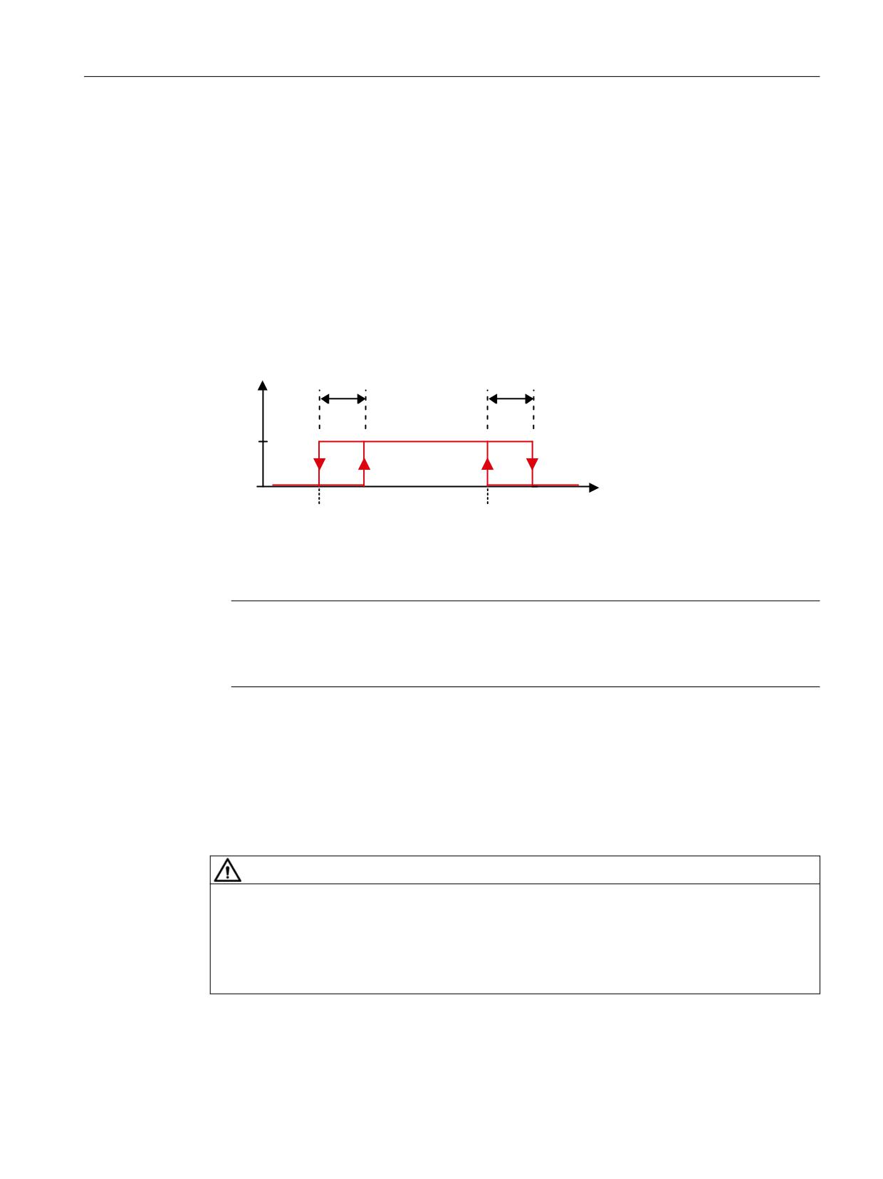
● Owing to variations in the cycle and signal propagation times, the output cam signals of the
two monitoring channels do not switch simultaneously and not precisely at the same
position. For this reason, enter a tolerance band for all output cam types via parameter
p9540. Within this tolerance band, the monitoring channels can have different signal states
for the same output cam:
U
6&$ WROHUDQFH
6&$ WROHUDQFH
S
S
[
S
>[@
S
>[@
3RVLWLRQ
3RVLWLRQ
0LQXV FDP
3OXV FDP
Figure 5-30
Parameterize output cam and tolerance
Note
The smallest possible tolerance range should be selected for the SCA function
(< 5 ... 10 mm). It makes sense to parameterize the cam tolerance to be greater than or
equal to the actual value tolerance.
● Reference the axis using the "General (Page 192)" function.
Enabling SCA
● You enable the SCA function with p9501.28 = 1.
● You enable each output cam individually with p9503.x = 1 (where x = 0 ... 29).
WARNING
Safe referencing
The enabled output cam signals are output immediately after POWER ON. However, this
output only safe after safe referencing has been performed. The cams are only considered as
being safe if they were safely referenced.
● Reference the axis using the "General (Page 192)" function.
Safety Integrated
Function Manual, 06/2020, 6SL3097-5AR00-0BP3
197
Description of Safety Integrated functions
5.3 Safety Integrated Advanced Functions
Select SCA
Select the SCA function using the PROFIsafe control word S_STW2.23. For SCA, you must
use telegram 903, in which control word S_STW2 and status word S_ZSW_CAM1 are available
for SCA.
Cam synchronization
For transmission of the output cam status word via PROFIsafe to the F host, the output cam
signals of the two monitoring channels are synchronized. Monitoring is also performed as to
whether a different output cam signal from the second channel is plausible. If the drive detects
an error, it outputs the message C01711 with the fault value 1014.
As the position tolerance for monitoring the output cam positions, the tolerance for the cross-
check of the actual position between the two monitoring channels in p9542 ("Actual value
comparison tolerance") is used.
Transmission via PROFIsafe
After SCA has been parameterized and selected, the monitoring results are transmitted in
status word S_ZSW_CAM1 (see Chapter "Additional process data (Page 234)").
Function diagrams (see SINAMICS S120/S150 List Manual)
●
2826
SCA (Safe Cam)
●
2844
S_ZSW_CAM1 Safety status word Safe Cam 1
Overview of important parameters (see SINAMICS S120/S150 List Manual)
● p9501
SI Motion enable safety functions (Control Unit)
● p9503
SI Motion SCA (SN) enable (Control Unit)
● p9505
SI Motion SP modulo value (Control Unit)
● p9536[0...29]
SI Motion SCA (SN) plus cam position (Control Unit)
● p9537[0...29]
SI Motion SCA (SN) minus cam position (Control Unit)
● p9540
SI Motion SCA (SN) tolerance (Control Unit)
● p9542
SI Motion actual value comparison tolerance (crosswise) (Control Unit)
● r9703.0...31
CO/BO: SI Motion SCA status signal (Control Unit)
● r9708[0...5]
SI Motion diagnostics safe position
● r9720.23
CO/BO: SI Motion drive-integrated control signals:
Deselect SCA
● r9727
SI Motion user agreement inside the drive
● r9771.22
SI shared functions: SCA supported
Safety Integrated
198
Function Manual, 06/2020, 6SL3097-5AR00-0BP3
Description of Safety Integrated functions
5.3 Safety Integrated Advanced Functions
5.3.7
Forced checking procedure (test stop)
The functions and switch-off signal paths must be tested at least once within a defined period
to establish whether they are working properly in order to meet the requirements of EN ISO
13849-1 and IEC 61508 in terms of timely error detection.
The maximum permissible interval for the forced checking procedure (test stop) for Basic and
Extended/Advanced Functions is 8760 hours; i.e. the forced checking procedure (test stop)
must be performed at least once per year.
This functionality must be implemented by initiating forced checking procedure (test stop)
cyclically either manually or as part of an automated process.
The test stop cycle is monitored. When the parameterized timer expires (also after POWER
ON / warm restart), alarm A01697: "SI Motion: Test of motion monitoring required" is generated
and a status bit is set which can be transferred to an output or to a PZD bit via BICO. This alarm
does not affect machine operation.
See also
Forced checking procedure (test stop) of the CU310-2 (Page 308)
Forced checking procedure (test stop) of the TM54F (Page 314)
Safety Integrated
Function Manual, 06/2020, 6SL3097-5AR00-0BP3
199
Description of Safety Integrated functions
5.3 Safety Integrated Advanced Functions
5.3.7.1
Performing a forced checking procedure (test stop)
Forced checking procedure (test stop) can be executed at the following points in time:
1.
Forced checking procedure (test stop) can be initiated application-specifically and can
therefore be executed at a time that suits application requirements.
This functionality is implemented by means of a single-channel parameter p9705, which can
be wired via BICO either to an input terminal on the drive unit (Control Unit) - or to a bit of any
arbitrary PZD.
In addition, it is possible to select the test stop via the Safety Control Channel (see Chapter
"Safety Info Channel and Safety Control Channel (Page 257)").
- p9559 SI Motion Forced checking procedure timer (Control Unit)
- p9705 BI: SI Motion test stop signal source
- r9723.0 CO/BO: SI Motion diagnostics signals integrated in the drive
If the test stop is executed as described, the action does not require a POWER ON. The
acknowledgment is set by canceling the test stop request.
2.
Forced checking procedure (test stop) can be automatically executed at POWER ON.
- To perform an automatic test stop of the Safety Integrated Extended/Advanced
Functions as well as an automatic test of the F-DO for the CU310-2, set p9507.6 = 1.
When testing the F-DO of the CU310-2, you must parameterize p10042 and activate the
test in p10046.
Note
Automatic forced checking procedure (test stop) and SBT
Automatic forced checking procedure (test stop) of the Safety Integrated Extended/
Advanced Functions is possible together with the "Brake test for test stop selection"
function (p10203 = 2).
- To perform automatic forced checking procedure (test stop) of the F-DI and F-DO of the
TM54F, set p10048 = 1.
- Even if you have parameterized forced checking procedure (test stop) for POWER ON,
you can still initiate a test stop at any time through the application.
- If the automatically initiated function cannot be correctly completed as a result of a
problem (e.g. communication failure), the function will be automatically restarted after
the problem has been resolved.
- After the forced checking procedure (test stop) has been performed successfully, the
converter goes into the "Ready" state.
- Timer p9559 is reset as a result of the automatic forced checking procedure (test stop).
- The automatic forced checking procedure (test stop) for POWER ON does not influence
the Safety Integrated Functions.
In all cases, the scope of forced checking procedure (test stop) function is identical.
Safety Integrated
200
Function Manual, 06/2020, 6SL3097-5AR00-0BP3
Description of Safety Integrated functions
5.3 Safety Integrated Advanced Functions
5.3.7.2
Safety devices
When the appropriate safety devices are implemented (e.g. protective doors), it can be
assumed that running machinery will not pose any risk to personnel. The user is therefore only
informed that the forced checking procedure (test stop) is due in the form of an alarm, which
requests the user to perform forced checking procedure (test stop) at the next possible
opportunity.
Examples of when the forced checking procedure (test stop) must be performed:
● When the drives are at a standstill after the system has been switched on (POWER ON).
● Before the protective door is opened.
● At defined intervals (e.g. every 8 hours).
● In automatic mode (time and event dependent).
Note
Preconditions
STO is triggered when a test stop is carried out for the Safety functions. It is not permissible that
STO is selected before selecting the test stop.
When blocksize Power Modules are used, the test stop must be triggered under controlled
standstill conditions (speed setpoint setting of 0, current is flowing through the motor).
5.3.7.3
Forced checking procedure (test stop) F-DI/F-DO of TM54F
An automatic test stop function is available for the forced checking procedure (test stop) to test
the F-DI/F-DO.
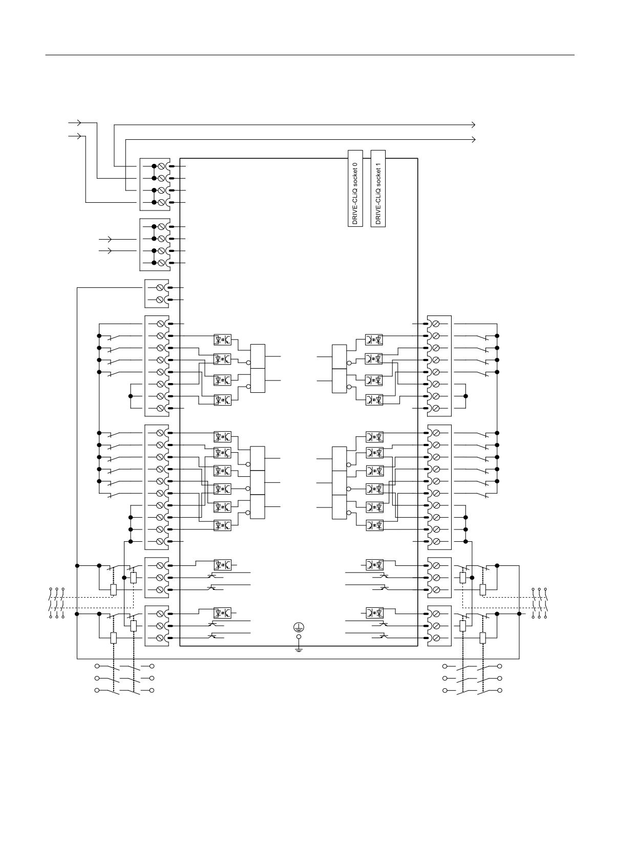
To ensure that the test stop function of the TM54F can be used, the F-DIs that are used must
be interconnected according to the following wiring example. The digital inputs of F-DI 0 to F-
DI 4 must connected to the "L1+" power supply. The digital inputs of F-DI 5 to F-DI 9 must
connected to the "L2+" power supply.
Safety Integrated
Function Manual, 06/2020, 6SL3097-5AR00-0BP3
201
Description of Safety Integrated functions
5.3 Safety Integrated Advanced Functions
Connection example for TM54F
3
0
0
;
;
;
9 (OHFWURQLFV
0
0
0
0
;
9
3
B
0
0
0
7HUPLQDO 0RGXOH 70
)
0
0
;
/
0
;
;
/
/
',
',
',
0
0
',
) ',
) ',
',
',
',
',
) ',
) ',
',
',
0
0
',
',
0
0
;
;
',
',
',
0
0
',
',
) ',
) ',
',
',
',
',
0
) ',
) ',
0
',
',
',
',
) ',
) ',
',
',
0
0
',
',
',
0
0
;
;
',
',
0
0
'2
'2
9
) '2
) '2
9
'2
'2
0
0
;
;
',
',
0
0
'2
'2
/
9
) '2
) '2
9
'2
'2
0
0
7KH LQYHUVLRQ FDQ EH SDUDPHWHUL]HG S
Figure 5-31
Connection example for TM54F
Safety Integrated
202
Function Manual, 06/2020, 6SL3097-5AR00-0BP3

Description of Safety Integrated functions
5.3 Safety Integrated Advanced Functions
Details on F-DIs and F-DOs
● The F-DIs must be registered for the test stop using p10041.
Note
F-DI not operational during the test
The F-DI states are frozen for the duration of the test!
● Ensure that the states of the F-DIs are not evaluated during the test.
● The associated F-DOs must be registered for the test stop using p10046.
Note
F-DOs during the time period of the test stop
F-DOs, which are not registered for evaluation using p10046, are set to "0" for the duration
of the test stop ("failsafe values").
Maximum test stop time period is: TTest stop = TFDIs + TFDOs
● Testing F-DIs: TFDIs = 3 · r10015 + 3 · X ms
(X = 20 ms or r10015 or p10017 - the greatest time value of the 3 values determines the
waiting time X)
● Test of the F-DOs: TFDOs = 8 · r10015 + 6 · Y ms
(Y = p10001 or r10015 or p10017 - the longest time of the 3 values determines the wait
time Y)
The Safety Integrated Functions of the TM54F are executed in the sampling time displayed
in r10015. This sampling time corresponds to the lowest value of the communication
sampling time entered in p10000[0..5].
Note
Manual dynamization required for specific F-DIs or F-DOs
It is possible that this test stop function cannot be used for certain F-DIs or F-DOs because of
the devices that are connected.
● Ensure dynamic operation of the affected F-DIs/F-DOs by other means, e.g. switch
operation or triggering certain machine functions.
Safety Integrated
Function Manual, 06/2020, 6SL3097-5AR00-0BP3
203
Description of Safety Integrated functions
5.3 Safety Integrated Advanced Functions
Performing a forced checking procedure (test stop)
● The test stop should be executed at a suitable point in time. This is the reason that it must
be initiated by the application or carried out at POWER ON. This functionality is
implemented using parameter p10007, which can be wired via BICO either to an input
terminal on the drive unit (CU), or to a bit of any arbitrary PZD.
● Forced checking procedure (test stop) can be automatically executed at POWER ON.
- If an automatic test stop of F-DI and F-DO of the TM54F is to be executed, then set
p10048 = 1.
- Even if you have parameterized the test stop for POWER ON, you can still initiate a test
stop at any time through the application.
- If the automatically initiated function cannot be correctly completed as a result of a
problem (e.g. communication failure), then after the problem has been resolved, the
function is automatically restarted.
- After forced checking procedure (test stop) has been successfully executed, the TM54F
goes into the "Ready" state.
- Timer p9559 is reset as a result of the automatic forced checking procedure (test stop).
- The automatic test stop for POWER ON does not influence the Safety Integrated
Functions.
The test stop cycle is monitored. When the parameterized timer expires (also after POWER
ON / warm restart), alarm A35014: "TM54F: Test stop required" is output.
● p10001
SI wait time for test stop at F-DO 0 ... 3
● p10003
SI Motion forced checking procedure timer
● p10007
BI: SI Motion forced checking procedure F-DO signal source
● p10041
SI TM54F F-DI enable for test
● p10046
SI Motion F-DO feedback signal input activation
Forced checking procedure (test stop) does not require a POWER ON, but it can be
automatically performed at POWER ON: The acknowledgment is set by canceling the test stop
request.
Note
Forced checking procedure (test stop) of the CU310-2
The description applies analogously to forced checking procedure (test stop) of the F-DO on
the CU310-2. You will find more instructions for carrying out test stops in Chapter "Forced
checking procedure (test stop) of the CU310-2 (Page 308)".
Note
Manual checking of F-DIs and/or F-DOs
If there are F-DIs and/or F-DOs that you do not wish to have checked automatically, or that
cannot be checked automatically (e.g. F-DIs of the CU310-2), the correct function of the
connected sensor/actuator and its response should be checked at suitable intervals by
actuating it.
Safety Integrated
204
Function Manual, 06/2020, 6SL3097-5AR00-0BP3
Description of Safety Integrated functions
5.3 Safety Integrated Advanced Functions
More information
Additional instructions for performing the test stops are provided in Chapters:
● Forced checking procedure (test stop) of the TM54F (Page 314)
● Forced checking procedure (test stop) of the CU310-2 (Page 308)
Safety Integrated
Function Manual, 06/2020, 6SL3097-5AR00-0BP3
205
Description of Safety Integrated functions
5.3 Safety Integrated Advanced Functions
Safety Integrated
206
Function Manual, 06/2020, 6SL3097-5AR00-0BP3

Control of the safety functions
6
6.1
Control possibilities
The following options for controlling Safety Integrated Functions are available:
Control via:
Basic
Extended
Advanced
Terminals (on the Control Unit and Motor/Power Mod-
x
-
-
ule)
PROFIsafe based on PROFIBUS or PROFINET
x
x
x
TM54F
x
x
x
Control without selection
-
SLS, SDI
-
Onboard F-DI/F-DO (CU310-2)
x1)
x
x
1)
Only the F-DI 0 can be used for the control. The F-DO is not available.
Note
PROFIsafe or TM54F
Using a Control Unit, control is possible either via PROFIsafe or TM54F. Mixed operation is not
permissible.
The safety-oriented input and output terminals (F-DI and F-DO) act as an interface between the
SINAMICS S120 Safety Integrated functionality and the process.
A dual-channel signal applied to an F-DI (Fail-safe Digital Input, safety-oriented digital input =
safe input terminal pair) controls the active monitoring of the activation/deactivation of safety
functions.
An F-DO (Fail-safe Digital Output, safety-oriented digital output = safe output terminal pair)
delivers a dual-channel signal representing feedback from the safety functions.
Dual-channel processing of I/O signals
A dual-channel structure is implemented for data input/output and for processing safety-
oriented I/O signals. All requests and feedback signals for safety-oriented functions should be
entered or tapped using both channels.
Safety Integrated
Function Manual, 06/2020, 6SL3097-5AR00-0BP3
207

Control of the safety functions
6.2 Control signals by way of terminals on the Control Unit and Motor / Power Module
6.2
Control signals by way of terminals on the Control Unit and Motor /
Power Module
Features
● Only for the Basic Functions
● Two-channel structure via two digital inputs (e.g. Control Unit / power unit)
● A debounce function can be applied to the terminals of the Control Unit and the Motor
Module to prevent incorrect trips due to signal disturbances or test signals. The filter times
are set using parameter p9651.
● Different terminal blocks depending on the format
● Automatic ANDing of up to eight digital inputs (p9620[0...7]) on the Control Unit for chassis
format power units connected in parallel
● The F-DI 0 is available on the CU310-2
Overview of the safety function terminals for SINAMICS S120
The different power unit formats of SINAMICS S120 have different terminal designations for the
inputs of the safety functions. These are shown in the following table.
Table 6-1
Inputs for safety functions
Module
1st switch-off signal path
2nd switch-off signal path (EP terminals)
(p9620[0])
Control Unit CU320-2
X122.1
6/X132.1…6
-
DI 0...7/16/17/20/21
Single Motor Module Book-
(see CU320-2)
X21.3 and X21.4
size/Booksize Compact
(on the Motor Module)
Single Motor Module/
(see CU320-2)
X41.1 and X41.2
Power Module Chassis
Double Motor Module Book-
(see CU320-2)
X21.3 and X21.4 (motor connection X1)
size/Booksize Compact
X22.3 and X22.4 (motor connection X2)
(on the Motor Module)
Power Module Blocksize
(see CU320-2)
X210.3 and X210.4 (on the CUA31/
with CUA31/CUA32
CUA32)
Control Unit CU310-2
X120.3
X120.4 and X120.51)
X121.1...4
Power Module Chassis with
(see CU310-2)
X41.1 and X41.2
CU310-2
Safety Integrated
208
Function Manual, 06/2020, 6SL3097-5AR00-0BP3

Control of the safety functions
6.2 Control signals by way of terminals on the Control Unit and Motor / Power Module
Module
1st switch-off signal path
2nd switch-off signal path (EP terminals)
(p9620[0])
Power Module blocksize
(see CU310-2)
STO_A and STO_B
with CU310-2
(for additional information, see Chapter
"STO via terminals of the Power Modules
Blocksize (Page 215)")
Controller Extension
X122.1...6
-
SIMOTION CX32-2
DI 0...3/16/17
1)
Please note: On the CU310-2, you must use the EP terminal (DI 17) as a switch-off signal path. Use
any free digital input (DI) as the 2nd switch-off signal path.
See the equipment manuals for additional information about the terminals.
Note
Function of the EP terminals
The EP terminals are only evaluated if the Safety Integrated Basic Functions are released via
onboard terminals.
Parallel connection of Motor Modules in chassis format
When Motor Modules in chassis format are connected in parallel, a safe AND element is
created on the parallel drive object. The number of indexes in p9620 corresponds to the number
of parallel chassis components in p0120.
6.2.1
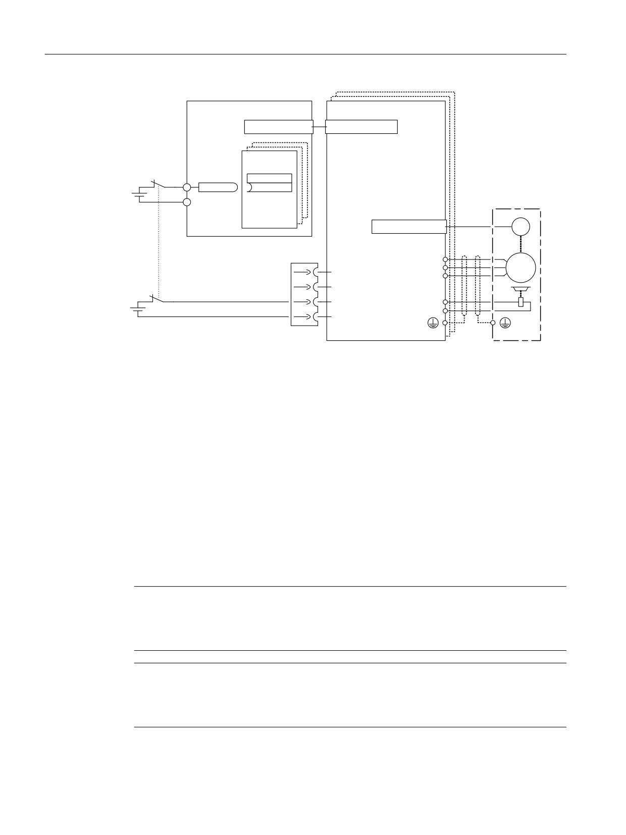
Description of the two-channel structure
The functions are separately selected/deselected for each drive using two terminals.
● Switch-off signal path, Control Unit (CU310-2/CU320-2)
The desired input terminal is selected via BICO interconnection (BI: p9620[0]).
● Switch-off signal path, Motor Module / Power Module (with CUA3x or CU310-2)
The input terminal is the "EP" terminal ("Enable Pulses").
Both terminals must be energized within the tolerance time p9650, otherwise a fault will be
output.
Safety Integrated
Function Manual, 06/2020, 6SL3097-5AR00-0BP3
209
Control of the safety functions
6.2 Control signals by way of terminals on the Control Unit and Motor / Power Module
&RQWURO 8QLW
0RWRU 0RGXOH
'5,9( &/L4
'5,9( &/L4
;
[
%,
;
[
', [
S
> @
U
[
&RQWURO 8QLW
PRQLWRULQJ FKDQQHO
0
'5,9( &/L4
*
;
;
8
0
9
7HPS
a
:
7HPS
0RWRU 0RGXOH
(3
9
%5
%5
PRQLWRULQJ FKDQQHO
(3 0
Figure 6-1
Example: Terminals for "Safe Torque Off": Example of Motor Modules Booksize and CU320-2
6.2.2
Grouping drives
Grouping drives (not for CU310-2)
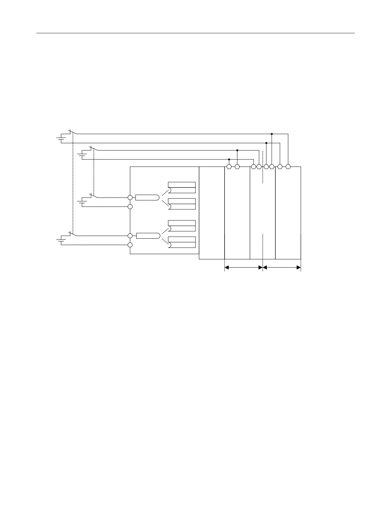
To ensure that the function works for more than one drive at the same time, the terminals for the
corresponding drives must be grouped together as follows:
1. Switch-off signal path
Connect the p9620 parameters of all drives that belong to a group with a single DI (r0722.x)
of the CU320-2.
2. Switch-off signal path (Motor Module / Power Module with CUA3x)
Wire the terminals for the individual Motor Modules / Power Modules, belonging to the
group, with CUA31/CUA32.
Note
Parameterization of the grouping
The grouping must be configured (DI on Control Unit) and wired (EP terminals) identically in
both monitoring channels.
Note
Response of STO for grouping
If a fault in a drive results in a "Safe Torque Off" (STO), this does not automatically mean that
the other drives in the same group also switch to "Safe Torque Off" (STO).
Safety Integrated
210
Function Manual, 06/2020, 6SL3097-5AR00-0BP3
Control of the safety functions
6.2 Control signals by way of terminals on the Control Unit and Motor / Power Module
The assignment is checked during the test for the switch-off signal paths. The operator selects
"Safe Torque Off" for each group. The check is drive-specific.
Example: Terminal groups
It must be possible to select/deselect "Safe Torque Off" separately for group 1 (drives 1 and 2)
and group 2 (drives 3 and 4). For this purpose, the same grouping for "Safe Torque Off" must
be realized both for the Control Unit and the Motor Modules.
&RQWURO 8QLW
0
0
0
6HOHFWLRQ
(3
0(3
(3
(3
'ULYH
GHVHOHFWLRQ
6HOHFWLRQ GHVHOHFWLRQ
*URXS
S
> @
',
*URXS
;
/LQH
6LQJOH
'RXEOH
6LQJOH
U
'ULYH
S
> @
0RGXOH
0RWRU
0RWRU
0RWRU
0
0RGXOH
0RGXOH
0RGXOH
'ULYH
S
> @
',
;
'ULYH
'ULYH
'ULYH
U
'ULYH
S
> @
0
*URXS
*URXS
Figure 6-2
Example: Grouping terminals with Motor Modules Booksize and CU320-2
6.2.3
Simultaneity and tolerance time of the two monitoring channels
The monitoring functions must be selected/deselected simultaneously in both monitoring
channels via the input terminals and only have an effect on the associated drive.
●
1 signal: Deselecting the function
●
0 signal: Selecting the function
The time delay that is unavoidable due to mechanical switching, for example, can be adapted
via parameters. The tolerance time, within which selection/deselection of the two monitoring
channels must occur if they are to be considered "simultaneous," is set in the following
parameters:
● p9650 (Basic Functions)
● p10002 (Extended/Advanced Functions)
Safety Integrated
Function Manual, 06/2020, 6SL3097-5AR00-0BP3
211

Control of the safety functions
6.2 Control signals by way of terminals on the Control Unit and Motor / Power Module
6.2.3.1
Tolerance time
Note
Parameterization of the tolerance time
In order to avoid that faults are incorrectly initiated, at these inputs the tolerance time must
always be set shorter than the shortest time between two switching events (ON/OFF, OFF/ON).
● If the monitoring functions are not selected/deselected within the tolerance time, this is
detected by the cross-check, and the following fault (STOP F) is output.
- F01611 (Basic Functions)
- C01770 (Extended/Advanced Functions)
For STO: In this case, the pulses have already been canceled as a result of the selection of
"Safe Torque Off" on one channel.
Note
Timing between the switching operations in the Basic Functions
Message F01611 with fault value 1000 is output if switching operations occur too frequently.
The cause depends on the type of control:
● Persistent signal changes occurred at the F-DI.
● STO was permanently triggered via PROFIsafe (also as subsequent response).
Within the time 5 · p9650, there must be at least two switching operations at the terminals
or via PROFIsafe with a minimum time between them of p9650.
● If the "Safe Stop 1" of the Basic Functions is not selected within the tolerance time in two
channels, this is detected by the cross-check, and fault F01611 (STOP F) is output. After the
set "SI Safe Stop 1 delay time" (p9652), the pulses are suppressed.
Note
In order that the drive can brake down to a standstill even when selected through one
channel, the time in p9652 must be shorter than the sum of the parameters for the data
cross-check (p9650 and p9658). Otherwise, the drive will coast down after the time p9650
+ p9658 has elapsed.
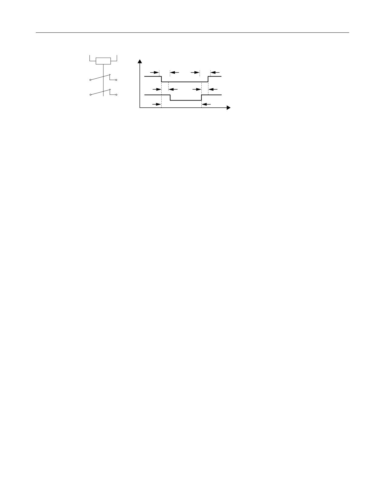
Further notes for setting the discrepancy time (also see the following diagram "Discrepancy
time") are provided in the "SINAMICS S120/S150 List Manual" for the following message:
● F01611 (Basic Functions)
● C01770 (Extended/Advanced Functions)
Safety Integrated
212
Function Manual, 06/2020, 6SL3097-5AR00-0BP3
Control of the safety functions
6.2 Control signals by way of terminals on the Control Unit and Motor / Power Module
7'
7'
75
75
6ZLWFKLQJ LQWHUYDO
76
W
7R EH PDLQWDLQHG
76
!
7'
!
75
TS
Switching interval
TD
Discrepancy time
TR
Response time
Figure 6-3
Discrepancy time
6.2.3.2
Overview of important parameters
Overview of important parameters (see SINAMICS S120/S150 List Manual)
● p9650
SI SGE switchover discrepancy time (Control Unit)
● p9652
SI Safe Stop 1 delay time (Control Unit)
● p9658
SI transition time STOP F to STOP A (Control Unit)
● p10002
SI Motion F-DI switchover discrepancy time (CPU 1)
Safety Integrated
Function Manual, 06/2020, 6SL3097-5AR00-0BP3
213
Control of the safety functions
6.2 Control signals by way of terminals on the Control Unit and Motor / Power Module
6.2.4
Bit pattern test
Bit pattern test of fail-safe outputs
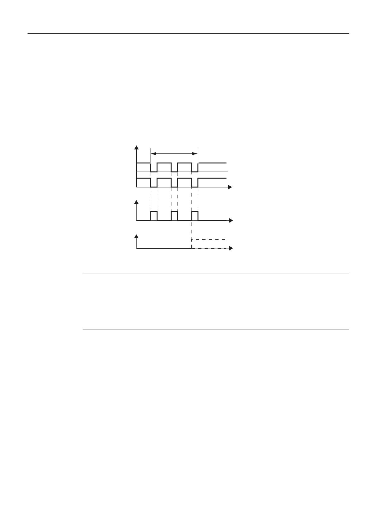
The converter normally responds immediately to signal changes in its fail-safe inputs. This is
not desired in the following case: Several control modules test their fail-safe outputs using bit
pattern tests (on/off tests), in order to identify faults due to either short-circuit or cross-circuit
faults. When you interconnect a fail-safe input of the converter with a fail-safe output of a control
module, the converter responds to these test signals.
,QSXW VLJQDOV
%LW SDWWHUQ WHVW
) ',
W
6DIHW\ IXQFWLRQ
$FWLYH
,QDFWLYH
W
)DXOW )
W
Figure 6-4
Converter response to a bit pattern test
Note
Debounce time for unwanted triggering of Safety Integrated functions
If the test pulses cause an unwanted triggering of the Safety Integrated functions, these test
pulses can be suppressed using the F-DI input filter (p9651 for Basic Functions or p10017 for
Extended/Advanced Functions). To do this, a value must be entered in p9651 or p10017 that
is greater than the duration of a test pulse.
Overview of important parameters (see SINAMICS S120/S150 List Manual)
● p9651
SI STO/SBC/SS1 debounce time (Control Unit)
● p10017
SI Motion digital inputs debounce time (CPU 1)
Safety Integrated
214
Function Manual, 06/2020, 6SL3097-5AR00-0BP3

Control of the safety functions
6.2 Control signals by way of terminals on the Control Unit and Motor / Power Module
6.2.5
STO via terminals of the Power Modules Blocksize
PM240-2 Power Modules, FSD to FSG
The Safe Torque Off (STO) safety function is used to safely disconnect the power feed to the
motor that generates the torque.
Using PM terminals - STO_A and STO_B - as well as 2 DIP switches, you can use the "Safe
Torque Off" (STO) function for the CU310-2 Control Units or the CU320-2 with CUA32 using the
Power Module hardware. This hardware-based STO can be used up to PL e according to
EN 13849-1 and SIL3 according to IEC 61508 with the appropriate application engineering.
Power Module
Control Unit
PM240-2 FSD … FSG
CU310-2
CU320-2 with CUA32
Requirements
● You can only use the STO terminals of the Power Module with the SINAMICS S120 Control
Units if you do not use any safety functions on the Control Unit.
If you use both safety function packages (STO terminals on the Power Module and Basic/
Extended/Advanced Functions) simultaneously, they will interfere with each other.
● A higher-level control system is required to select the STO safety function.
● The parameters of the digital outputs for the STO feedback are correctly assigned. The
converter signals to the higher-level control system that the STO safety function is being
controlled via 2 digital outputs.
For converters FSD…FSG, you must interconnect the feedback signals "STO is active" with
2 digital outputs of the Control Unit:
- r1838.3
- r1838.4
● The higher-level control system monitors the selection of the STO safety function and the
feedback from the converter.
● Forced checking procedure (test stop)
The higher-level control system regularly selects the STO safety function and evaluates the
converter feedback signal. We recommend that you implement a time monitoring function
in the higher-level control system, which issues an alarm if a test stop is overdue.
Note
Diagnostics
The state of the switch-off signal paths can be monitored using 2 digital outputs of the Control
Unit. You can find additional information in the SINAMICS S120/S150 List Manual.
You can find details on the clamps and DIP switchers here: Terminals STO_A/STO_B and DIP
switch (Page 217)
Safety Integrated
Function Manual, 06/2020, 6SL3097-5AR00-0BP3
215
Control of the safety functions
6.2 Control signals by way of terminals on the Control Unit and Motor / Power Module
Prerequisites for SIL 2/PL d
● Suitable higher-level controllers
- SIRIUS 3SK1
1-channel static feedback circuit
- SIRIUS 3SK2
2-channel dynamic feedback circuit
- MSS 3RK3
2-channel dynamic feedback circuit
- SIMATIC
Feedback circuit monitoring in the safety program
● Forced checking procedure (test stop) once per year
Prerequisites for SIL 3/PL e
● Suitable higher-level controllers
- SIRIUS 3SK2
2-channel dynamic feedback circuit
- MSS 3RK3
-
2-channel dynamic feedback circuit
– SIMATIC
Feedback circuit monitoring in the safety program
● Forced checking procedure (test stop) every 3 months
For the forced checking procedure, the STO feedback must be time-delayed.
Application examples
You can find application examples in the Service and Support Portal (https://
support.industry.siemens.com/cs/ww/en/view/109766026).
Safety Integrated
216
Function Manual, 06/2020, 6SL3097-5AR00-0BP3
Control of the safety functions
6.2 Control signals by way of terminals on the Control Unit and Motor / Power Module
6.2.5.1
Terminals STO_A/STO_B and DIP switch
Terminals STO_A/STO_B
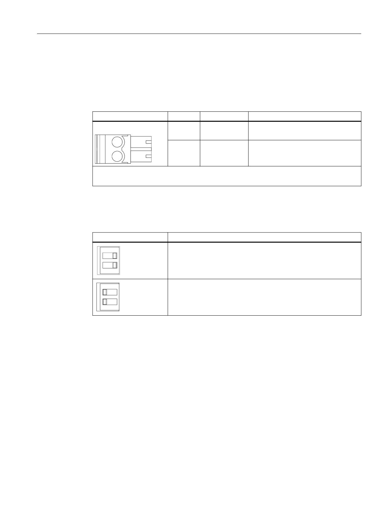
Table 6-2
Terminals STO_A/STO_B for the safety function "Safe Torque Off"
Terminal
Signal name
Technical data
Terminal:
1
STO_A/STO_B
Voltage: 24 V DC (20.4 … 28.8 V)
Current consumption: max. 1.0 A
2
M
Ground
● Type: Screw-type terminal 2 (see Manual SINAMICS S120 AC Drive, Chapter "Screw terminals")
● Maximum connectable cross-section: 2.5 mm2
DIP switch
Table 6-3
DIP switches for the safety function "Safe Torque Off" via terminals of the Power Module
DIP switch
Application
To use Safety Integrated of the CU310-2, deactivate the function "STO via
Power Module terminals" by setting both the DIP switches for the interface
STO_A/STO_B to the "0" position.
To enable the "Safe Torque Off" safety function via Power Module termi-
nals, you must set both DIP switches to the "1" position.
Safety Integrated
Function Manual, 06/2020, 6SL3097-5AR00-0BP3
217
Control of the safety functions
6.3 Activation via PROFIsafe
6.3
Activation via PROFIsafe
As an alternative to controlling Safety Integrated Functions via terminals, TM54F or on-board
terminals on the CU310-2, they can also be controlled via PROFIsafe. For communication via
PROFIBUS and PROFINET, use one of the following PROFIsafe telegrams: 30, 31, 901, 902
and 903
Control via PROFIsafe is available for both Safety Integrated Basic Functions, Safety
Integrated Extended Functions and the Safety Integrated Advanced Functions.
Note
Timing between the switching operations
Message F01611 with fault value 1000 is output if switching operations occur too frequently.
The cause depends on the type of control:
● Persistent signal changes occurred at the F-DI.
● STO was permanently triggered via PROFIsafe (also as subsequent response).
Within the time 5 · p9650, there must be at least two switching operations at the terminals or via
PROFIsafe with a minimum time between them of p9650.
6.3.1
Assigning Safety Integrated Functions to PROFIsafe
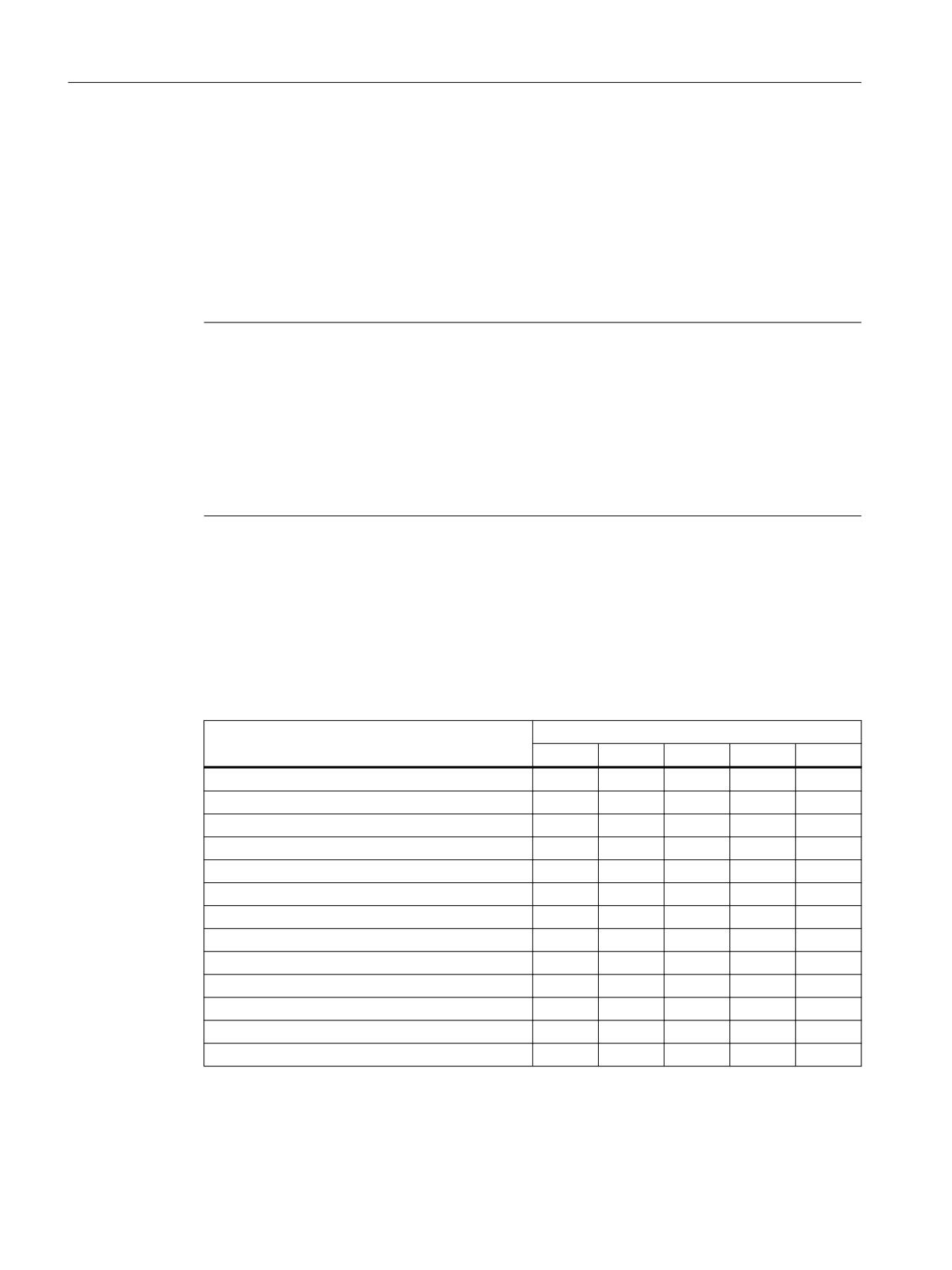
The following table provides you with an overview of which Safety Integrated functions you can
control with which PROFIsafe telegram.
Table 6-4
Assigning Safety Integrated functions to PROFIsafe telegrams
Safety function
PROFIsafe telegram
30
31
901
902
903
STO
x
x
x
x
x
SS1
x
x
x
x
x
SOS
x
x
x
x
x
SS2
x
x
x
x
x
SS2E
-
x
x
x
x
SLS
x
x
x
x
x
SSM1)
x
x
x
x
x
SDI
x
x
x
x
x
SLP
x2)
x
x
x
x
SCA
-
-
-
-
x
SLA
x
x
x
x
x
SP
-
-
x
x
-
Safe gearbox stage switchover
-
x
x
x
x
1)
As feedback signal in S_ZSW1 and S_ZSW2
2)
Without safety-related switchover between 2 different position ranges
Safety Integrated
218
Function Manual, 06/2020, 6SL3097-5AR00-0BP3
Control of the safety functions
6.3 Activation via PROFIsafe
6.3.2
Enabling of the control via PROFIsafe
For PROFIsafe communication, SINAMICS devices require a PROFIBUS or a PROFINET
interface. Every drive with configured PROFIsafe in the drive unit represents a PROFIsafe
slave (F slave or F device) with a fail-safe communication to the F host via PROFIBUS or
PROFINET and is assigned its own PROFIsafe telegram.
In this case, a PROFIsafe channel, known as a safety slot, is created using the Startdrive
commissioning tool and transferred to HW Config (alternatively, this safety slot can be created
by the SIMATIC Manager Step 7 using HW Config). The Safety Integrated Functions can then
be additionally controlled via the PROFIsafe telegrams 30, 31, 901, 902 and 903. The structure
of the associated control and status words is described below (see Chapter "Telegram format
(Page 221)"). The selected PROFIsafe telegrams for Safety Integrated are placed in front of the
standard telegram for communication (e.g. telegram 2).
Enabling PROFIsafe
The Safety Integrated Functions are enabled via PROFIsafe using parameters p9601:
● Basic Functions: p9601 = 8 hex or 9 hex
● Extended/Advanced Functions: p9601 = C hex or D hex
Note
License requirement for Safety Integrated Functions via PROFIsafe
No license is required to use Basic Functions. This also applies for control via PROFIsafe.
However, for Extended Functions or Advanced Functions, you require an appropriate license
that will be charged for.
All parameters involved in PROFIsafe communication are password protected against
undesirable changes and secured using a checksum. The telegram configuration is performed
in the hardware configuration in the F-host (see Chapters "PROFIsafe via PROFIBUS
(Page 321)" and "PROFIsafe via PROFINET (Page 322)").
Safety Integrated Basic Functions via PROFIsafe and via terminals
Control of the Basic Functions via terminals on the Control Unit and on the Motor/Power Module
(parameters p9601.0 = 1) may be enabled in parallel. In order to be able to select SS1, an SS1
delay time p9652 > 0 must be configured. With PROFIsafe, both SS1 and STO can be selected.
Only SS1 is available for control via terminal.
Safety Integrated
Function Manual, 06/2020, 6SL3097-5AR00-0BP3
219

Control of the safety functions
6.3 Activation via PROFIsafe
STO takes priority over SS1, i.e. STO becomes active if SS1 and STO are simultaneously
selected.
Note
Double Motor Module in the case of PROFIsafe and a sampling time of 62.5 µs
In the case of a Double Motor Module, the converter issues message F01625 "Sign-of-life error
in safety data" if you also select the following options:
● Control of the Safety Integrated Basic Functions via PROFIsafe
● "Sampling times for internal control loops" p0115[0] = 62.5 µs
● "Current controller dynamics higher" (p1810.11 = 1)
In addition, message F30802 "Power unit: Time slice overflow" may occur.
The following options are available to you to remedy this problem:
● Use a Single Motor Module
● Deactivate "Current controller dynamics higher" (p1810.11 = 0)
● Increase the "Sampling times for internal control loops" (p0115[0]).
● Control the Safety Integrated Basic Functions via terminals.
6.3.3
Selecting a PROFIsafe telegram
Proceed as follows to define the PROFIsafe telegram:
1. In parameter p60022 select the required telegram.
2. In parameter p9611, select the same telegram number.
Note
Compatibility mode
If you set p9611 = 998 for p60022 = 0 (for instance, if you have upgraded the safety project
to firmware V4.5), then the PROFIsafe telegram 30 is also set as for p60022 = 30 and
p9611 = 30.
PROFIsafe configuration
The PROFIsafe address is required for control of the safety functions via PROFIsafe.
Note
You can only change communication parameters in Startdrive in the setting dialog.
1. Click the icon
"Telegram configuration"
The properties of the PROFINET interface are displayed in the Inspector window. The
"Cyclic data traffic" setting range is active. Here you define the telegrams for the drive
objects.
2. Click the <Add telegram> entry in the telegram configuration of "Drive axis_x".
Safety Integrated
220
Function Manual, 06/2020, 6SL3097-5AR00-0BP3

Control of the safety functions
6.3 Activation via PROFIsafe
3. Select the "Add safety telegram" option in the drop-down list of the entry:
Startdrive then inserts the "Safe actual value" and "Safe setpoint" lines. The relevant
PROFIsafe telegrams are preassigned.
4. Open the new "Safe setpoint" screen form (for Drive axis_x) in the Inspector window.
5. Correct the PROFIsafe address of the drive in the "F-address" field.
6. In the function view, switch back to the "control" screen form.
The value of the F-address is displayed in the "PROFIsafe address" (p9610) field. A
preassigned PROFIsafe telegram is displayed in the "PROFIsafe telegram no." drop-down
list.
7. Click "Accept values" to transfer the telegram from the default settings into the Safety
programming.
8. Select the desired stop response for a failure of the PROFIsafe communication in the
"PROFIsafe failure response" (p9612) drop-down list.
Note
Unique PROFIsafe addresses
You must ensure the unique assignment of the PROFIsafe address throughout the network and
the CPU.
● The failsafe I/O of PROFIsafe address type 1 is addressed clearly by its failsafe destination
address.
● The failsafe destination address of the failsafe I/O (drive units in this case) must be unique
for the entire failsafe I/O throughout the network and the CPU (system-wide). The failsafe
I/O of PROFIsafe address type 2, e.g. modules of the ET 200SP type, must also be taken
into account.
● Note also the corresponding documentation in the TIA Portal online help in Section
"SIMATIC Safety - Configuration and programming". (SDR001)
6.3.4
Telegram format
The PROFIsafe telegram received at the Control Unit is displayed in r9768, and the PROFIsafe
telegram to be sent, in parameter r9769.
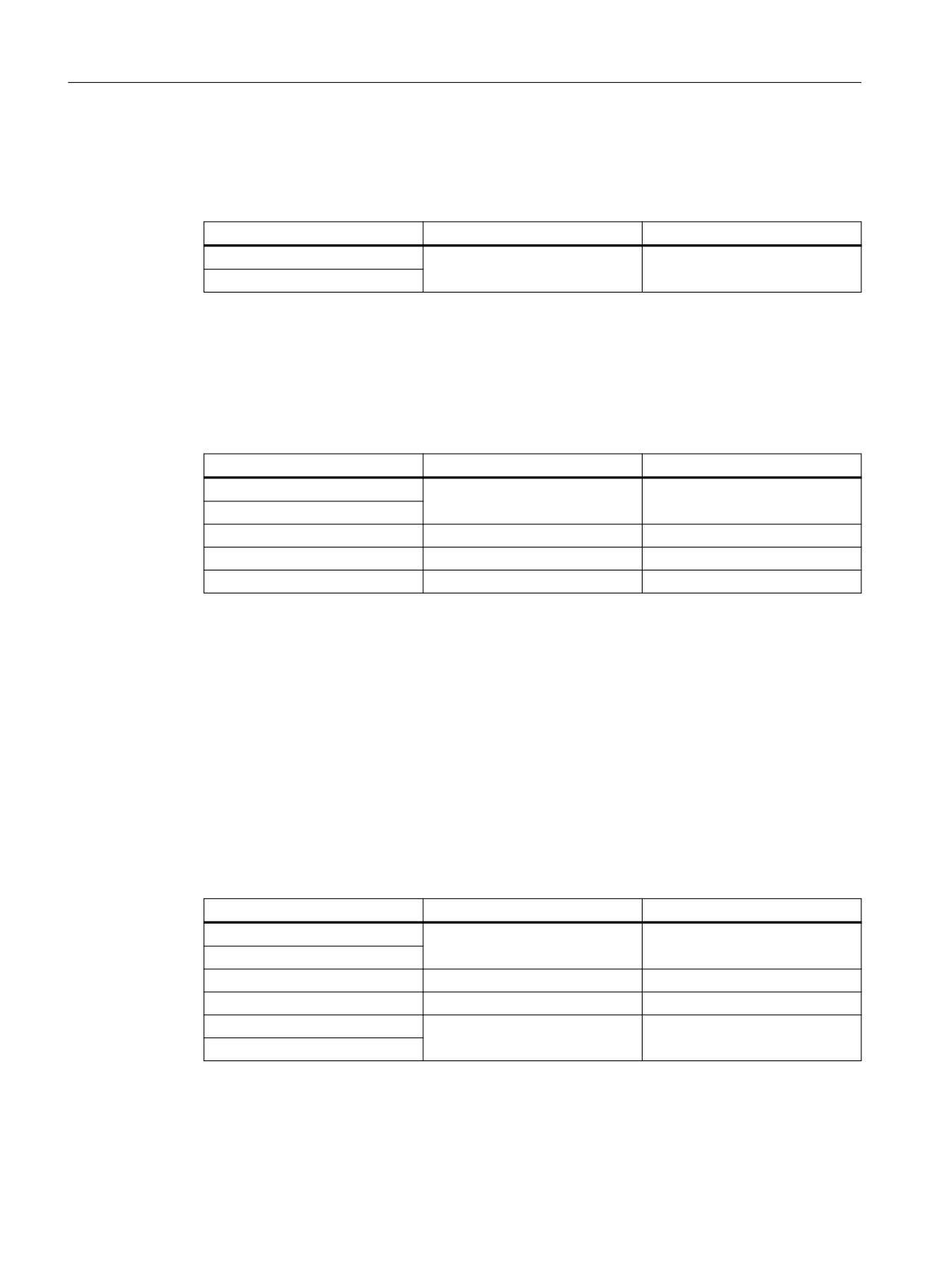
Structure of telegram 30
Telegram 30 transfers safety control word 1 (S_STW1) and safety status word 1 (S_ZSW1) as
user data. It is structured as follows:
Output data
Input data
PZD1
S_STW1
S_ZSW1
Safety Integrated
Function Manual, 06/2020, 6SL3097-5AR00-0BP3
221
Control of the safety functions
6.3 Activation via PROFIsafe
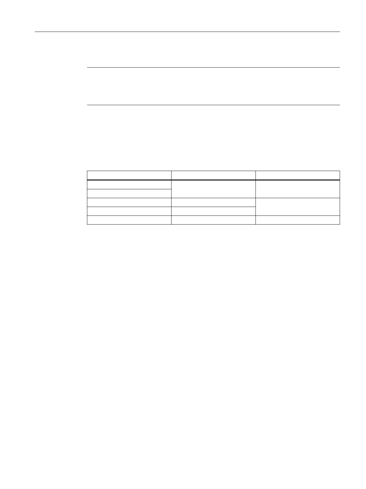
Structure of telegram 31
Telegram 31 transfers safety control word 2 (S_STW2) and safety status word 2 (S_ZSW2) as
user data. It is structured as follows:
Output data
Input data
PZD1
S_STW2
S_ZSW2
PZD2
Structure of telegram 901
Telegram 901 transfers the S_STW2, the variable SLS limit (S_SLS_LIMIT_A), the S_ZSW2,
the active SLS value of level 1 (S_SLS_LIMIT_A_ACTIVE), a counter value
(S_CYCLE_COUNT) and the safe position value in 16-bit format (S_XIST16) as user data. It is
structured as follows:
Output data
Input data
PZD1
S_STW2
S_ZSW2
PZD2
PZD3
S_SLS_LIMIT_A
S_SLS_LIMIT_A_ACTIVE
PZD4
-
S_CYCLE_COUNT
PZD5
-
S_XIST16
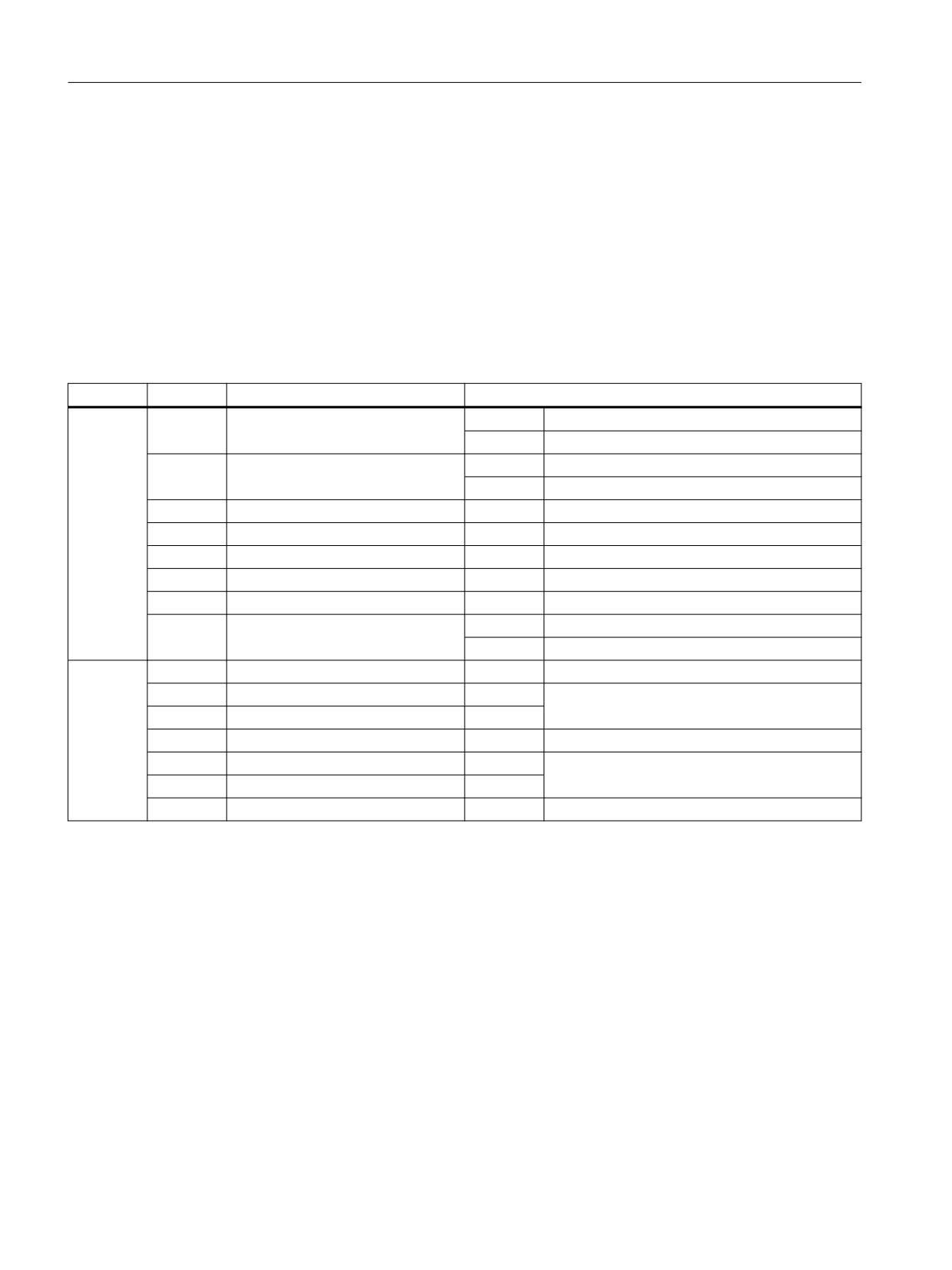
Structure of telegram 902
Telegram 902 transfers the following user data:
● S_STW2
● Variable SLS limit (S_SLS_LIMIT_A)
● S_ZSW2
● Active SLS value of level 1 (S_SLS_LIMIT_A_ACTIVE)
● One count value (S_CYCLE_COUNT)
● The safe position value in 32-bit format (S_XIST32).
Telegram 902 is structured as follows:
Output data
Input data
PZD1
S_STW2
S_ZSW2
PZD2
PZD3
S_SLS_LIMIT_A
S_SLS_LIMIT_A_ACTIVE
PZD4
-
S_CYCLE_COUNT
PZD5
-
S_XIST32
PZD6
Safety Integrated
222
Function Manual, 06/2020, 6SL3097-5AR00-0BP3
Control of the safety functions
6.3 Activation via PROFIsafe
Telegram 902 can only be used, if the higher-level controller (F-host) can process 32-bit values.
Note
Telegram 902 for SIEMENS products
STEP7 Safety in the TIA Portal can process this value. However, Distributed Safety in older
STEP 7 version cannot do this.
Structure of telegram 903
Telegram 903 transmits the following user data: S_STW2, S_SLS_LIMIT_A, S_ZSW2,
S_ZSW_CAM1 and S_SLS_LIMIT_A_ACTIVE.
Telegram 903 is structured as follows:
Output data
Input data
PZD1
S_STW2
S_ZSW2
PZD2
PZD3
S_SLS_LIMIT_A
S_ZSW_CAM1
PZD4
-
PZD5
-
S_SLS_LIMIT_A_ACTIVE
Safety Integrated
Function Manual, 06/2020, 6SL3097-5AR00-0BP3
223
Control of the safety functions
6.3 Activation via PROFIsafe
6.3.5
Process data
6.3.5.1
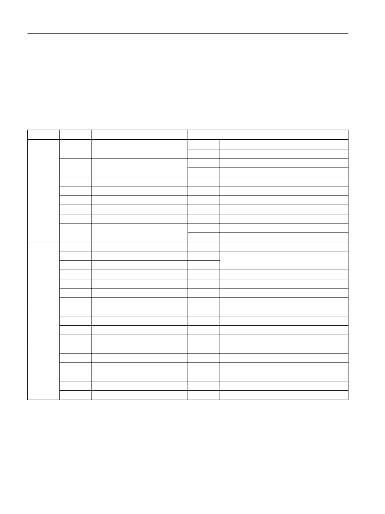
S_STW1 and S_ZSW1 (Basic Functions)
Safety control word 1 (S_STW1)
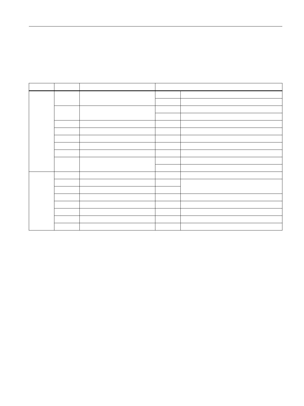
S_STW1, output signals
see function chart [2806].
Table 6-5
Description of safety-control word1 (S_STW1)
Byte
Bit
Meaning
Remarks
0
0
STO
1
Deselect STO
0
Select STO
1
SS1
1
Deselect SS1
0
Select SS1
2
SS2
0
-1)
3
SOS
0
-1)
4
SLS
0
-1)
5
Reserved
-
-
6
SLP
0
-1)
7
Internal Event ACK
1/0
Acknowledgment
0
No acknowledgment
1
0
SLA
0
-1)
1
Select SLS bit 0
0
-1)
2
Select SLS bit 1
0
3
Reserved
-
-
4
SDI positive
0
-1)
5
SDI negative
0
6, 7
Reserved
-
-
1)
Signals not relevant for Basic Functions: Should be set to "0".
Safety Integrated
224
Function Manual, 06/2020, 6SL3097-5AR00-0BP3
Control of the safety functions
6.3 Activation via PROFIsafe
Safety status word 1 (S_ZSW1)
S_ZSW1, input signals
see function diagram [2806].
Table 6-6
Description of safety status word 1 (S_ZSW1)
Byte
Bit
Meaning
Remarks
0
0
STO active
1
STO active
0
STO not active
1
SS1 active
1
SS1 active
0
SS1 not active
2
SS2 active
0
-1)
3
SOS active
0
-1)
4
SLS active
0
-1)
5
Reserved
-
-
6
SLP active
0
-1)
7
Internal Event
1
Internal event
0
No internal event
1
0
SLA active
0
-1)
1
Active SLS level bit 0
0
-1)
2
Active SLS level bit 1
0
3
SOS selected
0
-1)
4
SDI positive active
0
-1)
5
SDI negative active
0
-1)
6
Reserved
-
-
7
SSM (speed below limit value)
0
-1)
1)
Signals not relevant for Basic Functions: It is not permissible that they are evaluated.
Safety Integrated
Function Manual, 06/2020, 6SL3097-5AR00-0BP3
225
Control of the safety functions
6.3 Activation via PROFIsafe
6.3.5.2
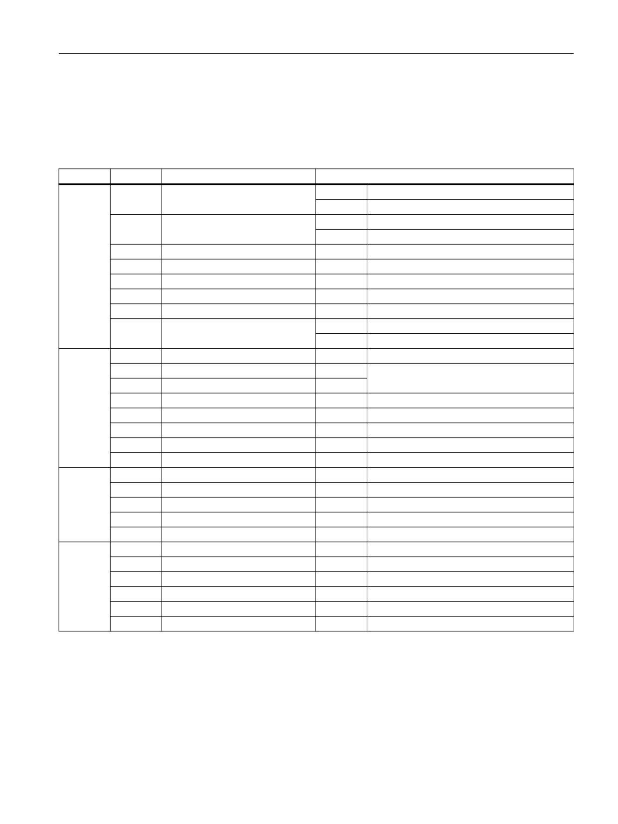
S_STW2 and S_ZSW2 (Basic Functions)
Safety control word 2 (S_STW2)
S_STW2, output signals
see function diagram [2806].
Table 6-7
Description of safety-control word 2 (S_STW2)
Byte
Bit
Meaning
Remarks
0
0
STO
1
Deselect STO
0
Select STO
1
SS1
1
Deselect SS1
0
Select SS1
2
SS2
0
-1)
3
SOS
0
-1)
4
SLS
0
-1)
5
Reserved
-
-
6
SLP
0
-1)
7
Internal Event ACK
1/0
Acknowledgment
0
No acknowledgment
1
0
SLA active
0
-1)
1
Select SLS bit 0
0
-1)
2
Select SLS bit 1
0
3
Reserved
-
-
4
SDI positive
0
-1)
5
SDI negative
0
-1)
6, 7
Reserved
-
-
2
0 ... 2
Reserved
-
-
3
Select SLP position range
0
-1)
4 ... 6
Reserved
-
-
7
SCA
0
-1)
3
0
Select gearbox stage, bit 0
0
-1)
1
Select gearbox stage, bit 1
0
-1)
2
Select gearbox stage, bit 2
0
-1)
3
Gearbox stage switchover
0
-1)
4
SS2E
0
-1)
5, 6, 7
Reserved
-
-
1)
Signals not relevant to Basic Functions should be set to "0".
Safety Integrated
226
Function Manual, 06/2020, 6SL3097-5AR00-0BP3
Control of the safety functions
6.3 Activation via PROFIsafe
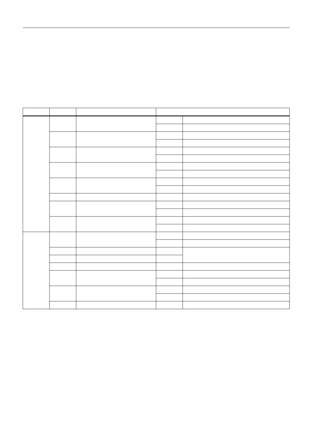
Safety status word 2 (S_ZSW2)
S_ZSW2, input signals
see function diagram [2806].
Table 6-8
Description of safety status word 2 (S_ZSW2)
Byte
Bit
Meaning
Remarks
0
0
STO active
1
STO active
0
STO not active
1
SS1 active
1
SS1 active
0
SS1 not active
2
SS2 active
0
-1)
3
SOS active
0
-1)
4
SLS active
0
-1)
5
Reserved
-
-
6
SLP active
0
-1)
7
Internal Event
1
Internal event
0
No internal event
1
0
SLA active
0
-1)
1
Active SLS level, bit 0
0
-1)
2
Active SLS level, bit 1
0
3
Reserved
-
-
4
SDI positive active
0
-1)
5
SDI negative active
0
-1)
6, 7
Reserved
-
-
7
SSM (speed)
0
-1)
2
0 ... 2
Reserved
-
-
3
SLP active position range
0
-1)
4, 5
Reserved
-
-
6
Safe position valid
0
-1)
7
Safely referenced
0
-1)
3
0 ... 2
F-DI 0 ... 22)
0
-1)
3
Reserved
-
-
4
SS2E active
0
-1)
5
SOS selected
0
-1)
6
SLP upper limit maintained
0
-1)
7
SLP lower limit maintained
0
-1)
1)
Signals not relevant for Basic Functions: It is not permissible that they are evaluated.
2)
Only valid for CU310-2.
Safety Integrated
Function Manual, 06/2020, 6SL3097-5AR00-0BP3
227
Control of the safety functions
6.3 Activation via PROFIsafe
6.3.5.3
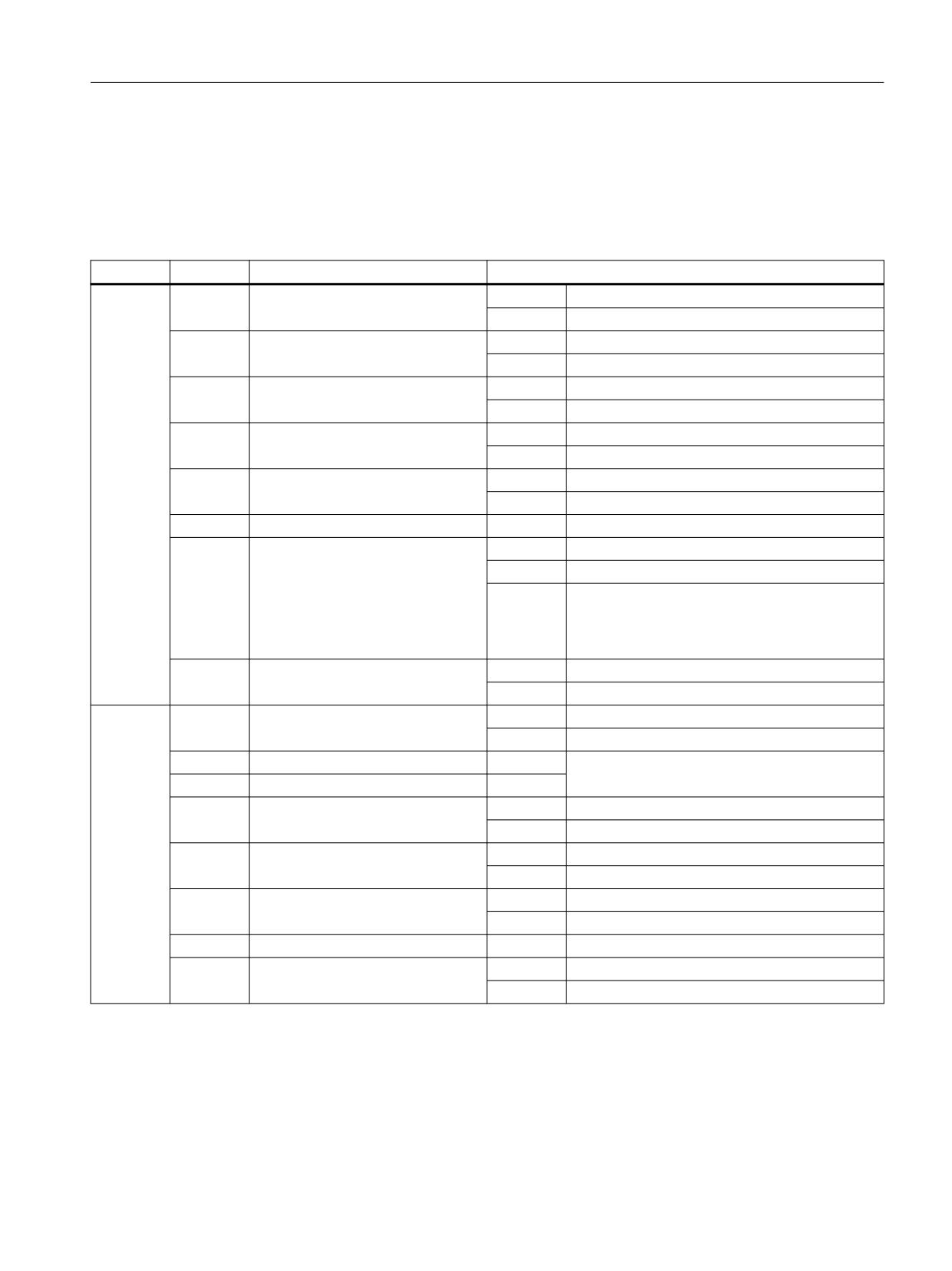
S_STW1 and S_ZSW1 (Extended/Advanced Functions)
Safety control word 1 (S_STW1)
S_STW1, output signals
see function chart [2842].
Table 6-9
Description of safety-control word1 (S_STW1)
Byte
Bit
Meaning
Remarks
0
0
STO
1
Deselect STO
0
Select STO
1
SS1
1
Deselect SS1
0
Select SS1
2
SS2
1
Deselect SS2
0
Select SS2
3
SOS
1
Deselect SOS
0
Select SOS
4
SLS
1
Deselect SLS
0
Select SLS
5
Reserved
-
-
6
SLP1)
1
Deselect SLP
0
Select SLP
7
Internal Event ACK
1/0
Acknowledgment
0
No acknowledgment
1
0
SLA
1
Deselect SLA
0
Select SLA
1
Select SLS bit 0
-
Select speed limit for SLS (2 bits)
2
Select SLS bit 1
-
3
Reserved
-
-
4
SDI positive
1
Deselect SDI positive
0
Select SDI positive
5
SDI negative
1
Deselect SDI negative
0
Select SDI negative
6, 7
Reserved
-
-
1)
Signals not relevant for Extended Functions: It is not permissible that they are evaluated.
Safety Integrated
228
Function Manual, 06/2020, 6SL3097-5AR00-0BP3
Control of the safety functions
6.3 Activation via PROFIsafe
Safety status word 1 (S_ZSW1)
S_ZSW1, input signals
see function diagram [2842].
Table 6-10
Description of safety status word 1 (S_ZSW1)
Byte
Bit
Meaning
Remarks
0
0
STO active
1
STO active
0
STO not active
1
SS1 active
1
SS1 active
0
SS1 not active
2
SS2 active
1
SS2 active
0
SS2 not active
3
SOS active
1
SOS active
0
SOS not active
4
SLS active
1
SLS active
0
SLS not active
5
Reserved
-
-
6
SLP active1)
1
SLP active
0
SLP not active
–
The status signal "SLP active" is not the same as
the diagnostic signal "SLP active" (r9722.6), but
is the AND logic operation of "SLP active"
(r9722.6) and "safely referenced" (r9722.23).
7
Internal Event
1
Internal event
0
No internal event
1
0
SLA active
1
SLA active
0
SLA not active
1
Active SLS level bit 0
-
Display of the speed limit for SLS (2 bits)
2
Active SLS level bit 1
-
3
SOS selected
1
SOS selected
0
SOS deselected
4
SDI positive active
1
SDI positive active
0
SDI positive not active
5
SDI negative active
1
SDI negative active
0
SDI negative not active
6
Reserved
-
-
7
SSM (speed)
1
SSM (speed below limit value)
0
SSM (speed higher than/equal to limit)
1)
Signals not relevant for Extended Functions: It is not permissible that they are evaluated.
Safety Integrated
Function Manual, 06/2020, 6SL3097-5AR00-0BP3
229
Control of the safety functions
6.3 Activation via PROFIsafe
6.3.5.4
S_STW2 and S_ZSW2 (Extended/Advanced Functions)
Safety control word 2 (S_STW2)
S_STW2, output signals
see function diagram [2843].
Table 6-11
Description of safety-control word 2 (S_STW2)
Byte
Bit
Meaning
Remarks
0
0
STO
1
Deselect STO
0
Select STO
1
SS1
1
Deselect SS1
0
Select SS1
2
SS2
1
Deselect SS2
0
Select SS2
3
SOS
1
Deselect SOS
0
Select SOS
4
SLS
1
Deselect SLS
0
Select SLS
5
Reserved
-
-
6
SLP1
1
Deselect SLP
0
Select SLP
7
Internal Event ACK
1/0
Acknowledgment
0
No acknowledgment
1
0
SLA
1
Deselect SLA
0
Select SLA
1
Select SLS bit 0
-
Select speed limit for SLS (2 bits)
2
Select SLS bit 1
-
3
Reserved
-
-
4
SDI positive
1
Deselect SDI positive
0
Select SDI positive
5
SDI negative
1
Deselect SDI negative
0
Select SDI negative
6, 7
Reserved
-
-
2
0 ... 2
Reserved
-
-
3
Select SLP position range1)
1
Select SLP area 2 (SLP2)
0
Select SLP area 1 (SLP1)
4 ... 6
Reserved
-
-
7
SCA1)
1
Deselect SCA
0
Select SCA
Safety Integrated
230
Function Manual, 06/2020, 6SL3097-5AR00-0BP3
Control of the safety functions
6.3 Activation via PROFIsafe
Byte
Bit
Meaning
Remarks
3
0
Select gearbox stage, bit 0
-
Select gearbox stage (3 bits)
1
Select gearbox stage, bit 1
-
2
Select gearbox stage, bit 2
-
3
Gearbox stage switchover
1
With increased position tolerance
0
Without increased position tolerance
4
SS2E
1
Deselect SS2E
0
Select SS2E
5
SS2ESR
1
Deselect SS2ESR
0
Select SS2ESR
6, 7
Reserved
-
-
1)
Signals not relevant for Extended Functions: It is not permissible that they are evaluated.
Safety status word 2 (S_ZSW2)
S_ZSW2, input signals
see function diagram [2843].
Table 6-12
Description of safety status word 2 (S_ZSW2)
Byte
Bit
Meaning
Remarks
0
0
STO active
1
STO active
0
STO not active
1
SS1 active
1
SS1 active
0
SS1 not active
2
SS2 active
1
SS2 active
0
SS2 not active
3
SOS active
1
SOS active
0
SOS not active
4
SLS active
1
SLS active
0
SLS not active
5
Reserved
-
-
6
SLP active1
1
SLP active
0
SLP not active
–
The status signal "SLP active" is not the same as
the diagnostic signal "SLP active" (r9722.6), but
is the AND logic operation of "SLP active"
(r9722.6) and "safely referenced" (r9722.23).
7
Internal Event
1
Internal event
0
No internal event
Safety Integrated
Function Manual, 06/2020, 6SL3097-5AR00-0BP3
231

Control of the safety functions
6.3 Activation via PROFIsafe
Byte
Bit
Meaning
Remarks
1
0
SLA active
1
SLA active
0
SLA not active
1
Active SLS level bit 0
-
Display of the speed limit for SLS (2 bits)
2
Active SLS level bit 1
-
3
Reserved
-
-
4
SDI positive active
1
SDI positive active
0
SDI positive not active
5
SDI negative active
1
SDI negative active
0
SDI negative not active
6
Reserved
-
-
7
SSM (speed)
1
SSM (speed below limit value)
0
SSM (speed higher than/equal to limit)
2
0 ... 2
Reserved
-
-
3
SLP active position range1)
1
SLP area 2 (SLP2) active
0
SLP area 1 (SLP1) active
-
The status signal "SLP active position range" al-
ways corresponds to the diagnostic signal "SLP
active position range" (r9722.19).
4, 5
Reserved
-
-
6
Safe position valid
1
Safe position valid
0
Safe position invalid
7
Safely referenced
1
Safe position is applicable as "safely referenced"
0
Safe position is not applicable as "safely refer-
enced"
1)
Signals not relevant for Extended Functions: It is not permissible that they are evaluated.
Safety Integrated
232
Function Manual, 06/2020, 6SL3097-5AR00-0BP3

Control of the safety functions
6.3 Activation via PROFIsafe
Byte
Bit
Meaning
Remarks
3
0
F-DI 02)
1
F-DI 0 inactive
0
F-DI 0 active
1
F-DI 12)
1
F-DI 1 inactive
0
F-DI 1 active
2
F-DI 22)
1
F-DI 2 inactive
0
F-DI 2 active
3
SS2ESR
1
SS2ESR active
0
SS2ESR not active
4
SS2E active
1
SS2E active
0
SS2E not active
5
SOS selected
1
SOS selected
0
SOS deselected
6
SLP upper limit maintained1)
1
SLP: Upper limit maintained
0
SLP: Upper limit not maintained
–
The status signal "upper SLP limit maintained"
always corresponds to the diagnostic signal "up-
per SLP limit maintained" (r9722.30).
7
SLP lower limit maintained1)
1
SLP: Lower limit maintained
0
SLP: Lower limit not maintained
–
The status signal "lower SLP limit maintained"
always corresponds to the diagnostic signal "low-
er SLP limit maintained" (r9722.31).
1)
Signals not relevant for Extended Functions: It is not permissible that they are evaluated.
2)
Only valid for CU310-2.
Safety Integrated
Function Manual, 06/2020, 6SL3097-5AR00-0BP3
233
Control of the safety functions
6.3 Activation via PROFIsafe
6.3.5.5
Additional process data
S_SLS_LIMIT_A
● PZD3 in telegrams 901, 902 and 903, output signals
● SLS limit value input
● Value range 1 ... 32767; 32767 ≙ 100% of the 1st SLS level
S_SLS_LIMIT_A_ACTIVE
●
PZD3 in telegrams 901, 902 and 903, output signals
●
Active SLS limit value
●
Value range 1 ... 32767; 32767 ≙ 100%
●
Must only be evaluated if SLS 1 active and p9501.24 = 1.
S_CYCLE_COUNT
●
PZD4 in telegrams 901 and 902, input signals
●
Counter for the safety cycle
●
Value range -32768 ... +32767
●
May only be evaluated if the transfer of safe position values is active (p9501.25 = 1) and the
position value is valid (r9722.22 = r9722.23 = 1).
S_XIST16
●
PZD5 in telegram 901, input signals
●
Current actual position value (16 bits)
●
Value range ±32767
●
Scaling using p9574
Note
Scaling
It is not permissible that the position value transferred in S_XIST16 exceeds the value range
that can be represented. This is the reason that the safe position value of the drive (r9713[0])
can be allocated a scaling factor. The position value is divided by this factor before transfer.
As a consequence, a wider value range can be transferred with a reduced accuracy.
Example: For a position of -29.999 mm signaled in r9708[0] and r9708[1] and a scaling
factor of p9x74 = 1000, a numerical value of -29 is signaled to the controller.
●
S_XIST16 must only be evaluated if the transfer of safe position values is active
(p9501.25 = 1) and the position value is valid (r9722.22 = r9722.23 = 1).
Safety Integrated
234
Function Manual, 06/2020, 6SL3097-5AR00-0BP3
Control of the safety functions
6.3 Activation via PROFIsafe
S_XIST32
● PZD5 and PZD6 in telegram 902, input signals
● Current actual position value (32 bits)
● Value range ±737280000
● Unit: 1 μm (linear axis), 0.001 ° (rotary axis)
● S_XIST32 must only be evaluated if the transfer of safe position values is active
(p9501.25 = 1) and the position value is valid (r9722.22 = r9722.23 = 1).
S_ZSW_CAM1
S_ZSW_CAM1, Safe Cam
see function diagram [2844].
Table 6-13
Description of Safety status word Safe Cam (S_ZSW_CAM1)
Byte
Bit
Meaning
Remarks
0
0
Position at cam 1
1
Position is at cam 1
0
Position is not at cam 1
1
Position at cam 2
1
Position is at cam 2
0
Position is not at cam 2
2
Position at cam 3
1
Position is at cam 3
0
Position is not at cam 3
3
Position at cam 4
1
Position is at cam 4
0
Position is not at cam 4
4
Position at cam 5
1
Position is at cam 5
0
Position is not at cam 5
5
Position at cam 6
1
Position is at cam 6
0
Position is not at cam 6
6
Position at cam 7
1
Position is at cam 7
0
Position is not at cam 7
7
Position at cam 8
1
Position is at cam 8
0
Position is not at cam 8
Safety Integrated
Function Manual, 06/2020, 6SL3097-5AR00-0BP3
235

Control of the safety functions
6.3 Activation via PROFIsafe
Byte
Bit
Meaning
Remarks
1
0
Position at cam 9
1
Position is at cam 9
0
Position is not at cam 9
1
Position at cam 10
1
Position is at cam 10
0
Position is not at cam 10
2
Position at cam 11
1
Position is at cam 11
0
Position is not at cam 11
3
Position at cam 12
1
Position is at cam 12
0
Position is not at cam 12
4
Position at cam 13
1
Position is at cam 13
0
Position is not at cam 13
5
Position at cam 14
1
Position is at cam 14
0
Position is not at cam 14
6
Position at cam 15
1
Position is at cam 15
0
Position is not at cam 15
7
Position at cam 16
1
Position is at cam 16
0
Position is not at cam 16
2
0
Position at cam 17
1
Position is at cam 17
0
Position is not at cam 17
1
Position at cam 18
1
Position is at cam 18
0
Position is not at cam 18
2
Position at cam 19
1
Position is at cam 19
0
Position is not at cam 19
3
Position at cam 20
1
Position is at cam 20
0
Position is not at cam 20
4
Position at cam 21
1
Position is at cam 21
0
Position is not at cam 21
5
Position at cam 22
1
Position is at cam 22
0
Position is not at cam 22
6
Position at cam 23
1
Position is at cam 23
0
Position is not at cam 23
7
Position at cam 24
1
Position is at cam 24
0
Position is not at cam 24
Safety Integrated
236
Function Manual, 06/2020, 6SL3097-5AR00-0BP3
Control of the safety functions
6.3 Activation via PROFIsafe
Byte
Bit
Meaning
Remarks
3
0
Position at cam 25
1
Position is at cam 25
0
Position is not at cam 25
1
Position at cam 26
1
Position is at cam 26
0
Position is not at cam 26
2
Position at cam 27
1
Position is at cam 27
0
Position is not at cam 27
3
Position at cam 28
1
Position is at cam 28
0
Position is not at cam 28
4
Position at cam 29
1
Position is at cam 29
0
Position is not at cam 29
5
Position at cam 30
1
Position is at cam 30
0
Position is not at cam 30
6
SCA active
1
SCA is active
0
SCA is not active
7
Validity of the values from SCA
1
Values from SCA are valid
0
Values from SCA are not valid
6.3.6
Function diagrams and parameters
Function diagrams (see SINAMICS S120/S150 List Manual)
●
2840
SI functions - SI Motion drive-integrated control signals/status signals
●
2858
SI functions, control via PROFIsafe (p9601.2 = p9601.3 = 1)
Overview of important parameters (see SINAMICS S120/S150 List Manual)
● p9562[0...1]
SI Motion SLP (SE) stop response (Control Unit)
● p9563[0...3]
SI Motion SLS (SG)-specific stop response (Control Unit)
● p9566
SI Motion SDI stop response (Control Unit)
● p9580
SI Motion stop response delay bus failure (Control Unit)
● p9601
SI enable functions integrated in the drive (Control Unit)
● p9610
SI PROFIsafe address (Control Unit)
● p9611
SI PROFIsafe telegram selection (Control Unit)
● p9612
SI PROFIsafe failure response (Control Unit)
● p60022
Selecting a PROFIsafe telegram
Safety Integrated
Function Manual, 06/2020, 6SL3097-5AR00-0BP3
237

Control of the safety functions
6.4 Control via TM54F
6.4
Control via TM54F
Note
Commissioning TM54F
● TM54F is not yet available in Startdrive.
● You can find information on commissioning with STARTER in older editions of this manual.
The TM54F is a terminal expansion module for snapping onto a DIN EN 60715 mounting rail:
The TM54F features failsafe digital inputs and outputs for controlling and signaling the states
of the Safety Integrated Basic, Extended and Advanced Functions.
Note
DRIVE-CLiQ line of the TM54F
● A TM54F must be connected directly to a Control Unit via DRIVE-CLiQ.
● Each Control Unit can be assigned only one TM54F which is connected via DRIVE-CLiQ.
● Additional DRIVE-CLiQ nodes can be operated at the TM54F, such as Sensor Modules and
Terminal Modules (excluding an additional TM54F). It is not permissible that Motor Modules
and Line Modules are connected to a TM54F.
● In the case of a CU310-2 Control Unit, it is not possible to connect the TM54F to the DRIVE-
CLiQ line of a Power Module. The TM54F can only be connected to the sole DRIVE-CLiQ
X100 socket of the Control Unit.
Overview of the TM54F interfaces
Type
Number
Failsafe digital outputs (F-DO)
4
Failsafe digital inputs (F-DI)
10
Sensor1) power supplies, dynamic response supported2)
2
Sensor1) power supply, no dynamic response
1
Digital inputs for checking the F-DO for the forced checking procedure (test stop)
4
1)
Sensors: Failsafe devices for command operations and sensing (e.g. Emergency Stop pushbuttons,
safety door locks, position switches, and light arrays / light curtains).
2)
Dynamic response: The sensor power supply is switched on and off by the TM54F when the forced
checking procedure (test stop) is active for the sensors, cable routing, and the evaluation electronics.
The TM54F provides four failsafe digital outputs and ten failsafe digital inputs. A failsafe digital
output consists of a 24 VDC switching output, an output switching to ground and a digital input
for reading back the switching state. A failsafe digital input is made up of 2 digital inputs.
Function diagrams (see SINAMICS S120/S150 List Manual)
●
2890
SI TM54F - overview
Safety Integrated
238
Function Manual, 06/2020, 6SL3097-5AR00-0BP3

Control of the safety functions
6.4 Control via TM54F
6.4.1
Assigning Safety Integrated Functions to the F-DI/TM54F
The following table provides you with an overview of which Safety Integrated functions you can
control with which F-DI/F-DO (onboard or TM54F).
Table 6-14
Assigning Safety Integrated functions to F-DI/F-DO (onboard or TM54F)
Safety function
Onboard F-DI/F-DO
TM54F F-DI/F-DO
STO
x
x
SS1
x
x
SOS
x
x
SS2
x
x
SS2E
-
-
SLS
x
x
SSM1)
x
x
SDI
x
x
SLP
x
x
SCA
-
-
SLA
-
-
SP
-
-
Safe gearbox stage switchover
-
-
1)
As feedback signal in S_ZSW1 and S_ZSW2
6.4.2
Fault acknowledgment
You have the following options of acknowledging TM54F faults after troubleshooting:
● POWER ON
● Falling edge of the signal "Internal Event ACK" with subsequent acknowledgment on the
Control Unit ("fail-safe acknowledgment")
6.4.3
Overview of the F-DIs
Description
Failsafe digital inputs (F-DI) consist of 2 digital inputs. At the 2nd digital input, the cathode (M)
of the optocoupler is additionally brought out to enable connection of an output of a failsafe
controller grounded through a switch. (The anode must be connected to 24 V DC.)
Parameter p10040 is used to determine whether an F-DI is operated as NC/NC or NC/NO
contact. The status of each DI can be read at parameter r10051. The bits of both drive objects
are logically AND'ed and return the status of the relevant F-DI.
Test signals from F-DOs and interference pulses can be filtered out using the input filter
(p10017), so that they do not cause any faults.
Safety Integrated
Function Manual, 06/2020, 6SL3097-5AR00-0BP3
239
Control of the safety functions
6.4 Control via TM54F
Explanation of terms:
NC contact / NC contact: To select the safety function, a "zero level" must be present at both
inputs.
NC contact / NO contact: To select the safety function, a "zero level" must be present at input
1 and a "1 level" at input 2.
The signal states at the two associated digital inputs (F-DI) must assume the same status
configured in p10040 within the monitoring time set in p10002.
To enable the forced checking procedure (test stop), connect the digital inputs of F-DI 0 ... 4 of
the TM54F to the dynamic voltage supply L1+ and the digital inputs to F-DI 5 ... 9 to L2+.
Additional information for the forced checking procedure (test stop) is provided in Chapter
"General (Page 174)".
Table 6-15
Overview of the failsafe inputs in the SINAMICS S120/S150 List Manual:
Module
Function diagram
Inputs
TM54F
2893
F-DI 0 ... 4
2894
F-DI 5 ... 9
F-DI features
● Failsafe configuration with 2 digital inputs per F-DI
● Input filter to block test signals with an adjustable suppression time (p10017), see Chapter
"Bit pattern test (Page 214)".
● Configurable connection of NC/NC or NC/NO contacts by means of p10040
● Status parameter r10051
● Adjustable time window for monitoring discrepancy at both digital inputs by means of
parameter p10002 for all F-DIs
Note
Discrepancy time
To avoid that fault messages are incorrectly triggered ("nuisance tripping"), at these inputs the
discrepancy time must always be set less than the shortest time between 2 switching events
(ON/OFF, OFF/ON) (see also the following diagram "Discrepancy time").
Further notes for setting the discrepancy time are contained in the "SINAMICS S120/S150 List
Manual" for the following messages:
● F01611 (Basic Functions)
● C01770 (Extended/Advanced Functions)
Safety Integrated
240
Function Manual, 06/2020, 6SL3097-5AR00-0BP3
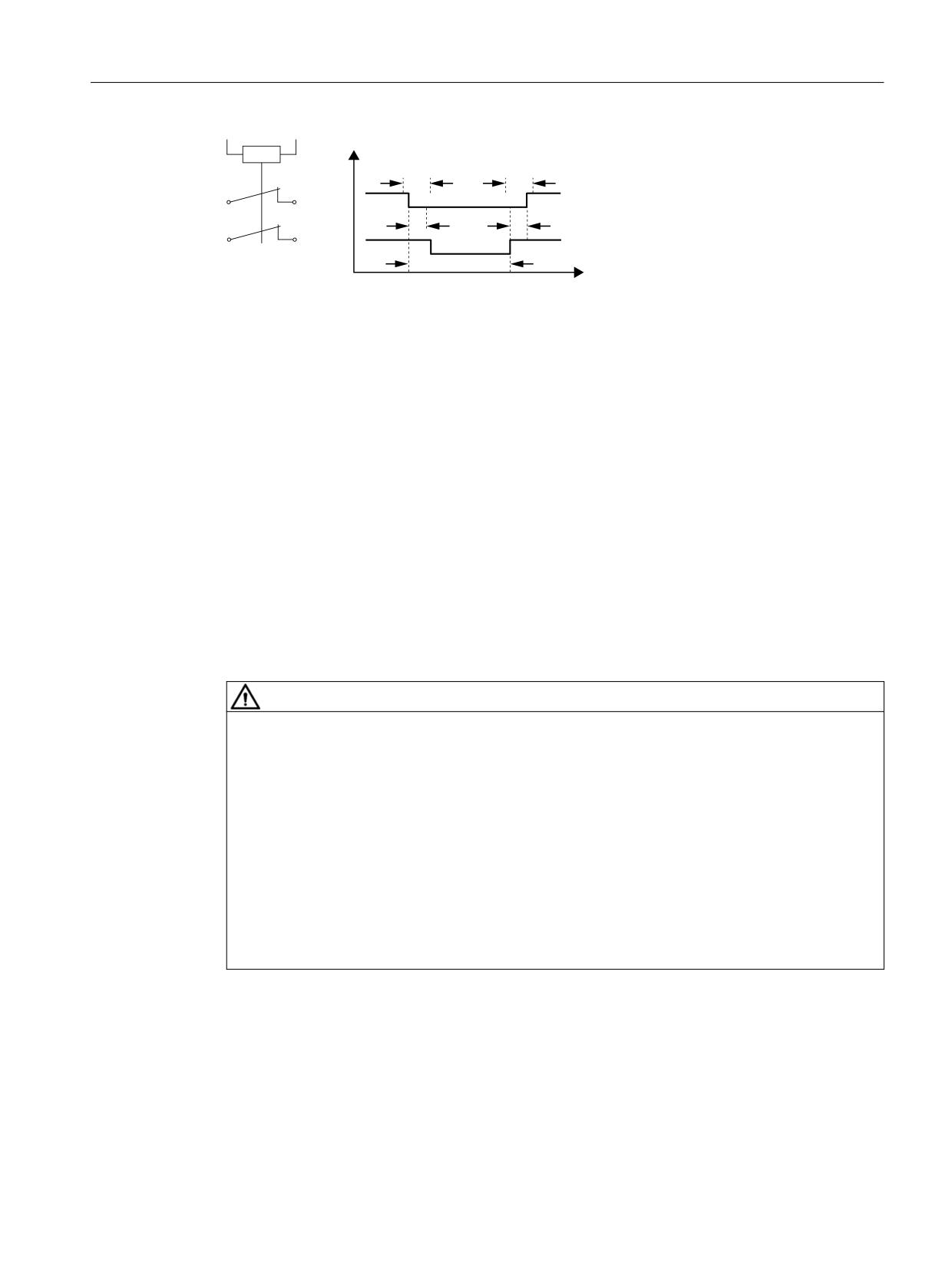
Control of the safety functions
6.4 Control via TM54F
7'
7'
75
75
6ZLWFKLQJ LQWHUYDO
76
W
7R EH PDLQWDLQHG
76
!
7'
!
75
TS
Switching interval
TD
Discrepancy time
TR
Response time
Figure 6-5
Discrepancy time
● Second digital input with additional tap of the optocoupler cathode for connecting a ground-
switching output of a failsafe controller.
● The signal states of the two digital inputs of the F-DIs are frozen at logical 0 (safety function
selected) when different signal states are present within a failsafe F-DI until a safe
acknowledgment has been carried out by means of an F-DI via parameter p10006 (SI
acknowledgment internal event input terminal).
● The monitoring time (p10002) for the discrepancy of the two digital inputs of an F-DI may
have to be increased so that switching operations do not trigger an undesired response,
thereby necessitating a safe acknowledgment. Therefore, the signal states at the two
associated digital inputs (F-DI) must have the same state within this monitoring time,
otherwise the following fault will be output F35151 "TM54F: Discrepancy error". This
requires safe acknowledgment.
WARNING
Unwanted movement due to incorrect signal states as a result of diagnostic currents in the
switched-off state (logical state "0" or "OFF")
Unlike mechanical switching contacts, e.g. emergency stop switches, diagnostic currents can
also flow when the semiconductor is in the switched-off state. If interconnection with digital
inputs is faulty, the diagnostic currents can result in incorrect switching states. Incorrect signal
states of digital inputs can cause unwanted movements of machine parts and result in serious
injury or death.
● Observe the conditions of digital inputs and digital outputs specified in the relevant
manufacturer documentation.
● Check the conditions of the digital inputs and digital outputs with regard to currents in the
"OFF" state and if necessary connect the digital inputs to suitably dimensioned, external
resistors to protect against the reference potential of the digital inputs.
More information on this topic is available on the Internet at: Parameterizing and configuring
Safety Integrated
Function Manual, 06/2020, 6SL3097-5AR00-0BP3
241
Control of the safety functions
6.4 Control via TM54F
Function diagrams (see SINAMICS S120/S150 List Manual)
●
2893
SI TM54F - Failsafe digital inputs (F-DI 0 ... F-DI 4)
●
2894
SI TM54F - Failsafe digital inputs (F-DI 5 ... F-DI 9)
Overview of important parameters (see SINAMICS S120/S150 List Manual)
● p10002
SI TM54F F-DI switchover discrepancy time
● p10017
SI TM54F digital inputs debounce time
● p10040
SI TM54F F-DI input mode
● r10051.0...9
CO/BO: SI TM54F digital inputs, status
6.4.4
Function of the F-DO
6.4.4.1
Overview of the F-DOs
Failsafe digital outputs (F-DO) consist of 2 digital outputs and 1 digital input that checks the
switching state for forced checking procedure (test stop). The 1st digital output switches 24 V
DC, and the 2nd switches the ground of the power supply of X514 (TM54F).
The status of each F-DO can be read at parameter r10052. The status of the associated DI can
be read at parameter r10053 (only available for TM54F_SL (TM54F Slave Module)).
The actuator connected to the F-DO can also be tested under specific conditions as part of
forced checking procedure (test stop). See Chapter "Forced checking procedure (test stop) of
the TM54F (Page 314)".
Table 6-16
Overview of the failsafe outputs in the SINAMICS S120/S150 List Manual:
Module
Function diagram
Outputs
Associated checking in-
puts
TM54F
2895
F-DO 0 ... 3
DI 20 ... 23
6.4.4.2
Signal sources
A drive group contains several drives with similar characteristics. The groups are
parameterized at the p10010 and p10011 parameters.
The following signals are available for interconnecting (p10042, ..., p10045) each one of the
four drive groups with the F-DO:
● STO active
● SS1 active
● SS2 active
● SOS active
● SLS active
● SSM feedback active
● Safe State
● SOS selected
● Active SLS level bit 0
● Active SLS level bit 1
Safety Integrated
242
Function Manual, 06/2020, 6SL3097-5AR00-0BP3
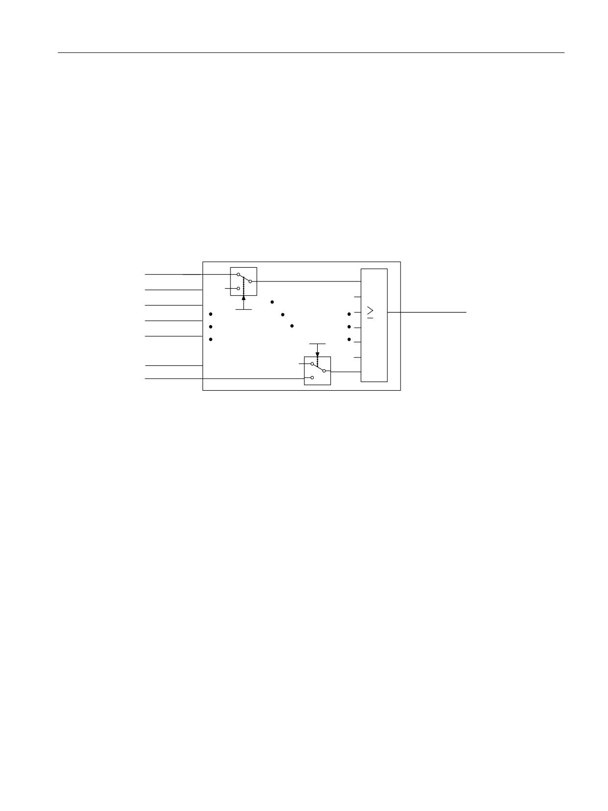
Control of the safety functions
6.4 Control via TM54F
● SDI positive active
● SDI negative active
● SLP active
● Active SLP area
● Internal event
The following (safe state) signals can be requested via p10039[0...3] for each drive group
(index 0 corresponds with drive group 1 etc.):
● STO active (power removed/pulses sup- ● SS1 active
pressed)
● SS2 active
● SOS active
● SLS active
● SLP active
● SDI positive active
● SDI negative active
3XOVH GHOHWHG
66 DFWLYH
66
DFWLYH
'ULYH JURXS [
6DIH VWDWH
626 DFWLYH
S
>[@
6/6 DFWLYH
S
>[@
6', SRVLWLYH DFWLYH
6', QHJDWLYH DFWLYH
6/3 DFWLYH
Figure 6-6
Safe state selection (example Extended/Advanced Functions)
The same signals (high-active) of each drive or drive group are logically linked by means of
AND operation. The different signals selected via p10039 are logically OR'ed. Result of these
logic operations is the "Safe State" for each drive group. You will find details in the SINAMICS
S120/S150 List Manual in function diagrams 2901 (Basic Functions) and 2906 (Extended/
Advanced Functions).
Each F-DO supports the interconnection of up to 6 signals by way of indexing (p10042[0...5] to
p10045[0...5]) and their output as logical AND operation.
6.4.4.3
Function diagrams and parameters
Function diagrams (see SINAMICS S120/S150 List Manual)
●
2893
SI TM54F - Failsafe digital inputs (F-DI 0 ... F-DI 4)
●
2894
SI TM54F - Failsafe digital inputs (F-DI 5 ... F-DI 9)
●
2895
SI TM54F - Failsafe digital outputs (F-DO 0 ... 3),
digital inputs (DI 20 ... 23)
●
2900
SI TM54F - Basic Functions control interface (p9601.2/3 = 0,
p9601.6 = 1)
●
2901
SI TM54F - Basic Functions Safe State selection
●
2902
SI TM54F - Basic Functions assignment (F-DO 0 ... F-DO 3)
●
2905
SI TM54F - Extended/Advanced Functions control interface
(p9601.2 = 1 & p9601.3 = 0)
Safety Integrated
Function Manual, 06/2020, 6SL3097-5AR00-0BP3
243
Control of the safety functions
6.4 Control via TM54F
●
2906
SI TM54F - Extended/Advanced Functions safe state selection
●
2907
SI TM54F - Extended/Advanced Functions assignment (F-DO 0 ... F-DO 3)
Overview of important parameters (see SINAMICS S120/S150 List Manual)
● p10039[0...3] SI TM54F Safe State signal selection
● p10042[0...5] SI TM54F F-DO 0 signal sources
● p10043[0...5] SI TM54F F-DO 1 signal sources
● p10044[0...5] SI TM54F F-DO 2 signal sources
● p10045[0...5] SI TM54F F-DO 3 signal sources
● r10051.0...9 CO/BO: SI TM54F digital inputs, status
● r10052.0...3
CO/BO: SI TM54F digital outputs, status
● r10053.0...3
CO/BO: SI TM54F digital inputs 20 ... 23, status
Safety Integrated
244
Function Manual, 06/2020, 6SL3097-5AR00-0BP3
Control of the safety functions
6.5 Communication failure via PROFIsafe or with TM54F
6.5
Communication failure via PROFIsafe or with TM54F
Factory setting for the response to communication failure
In the following cases, the drive responds with a STOP A.
● PROFIsafe communication to the higher-level control has failed.
● DRIVE-CLiQ communication with the TM54F has failed.
6.5.1
STOP B as response to communication failure with PROFIsafe control
Communication failure for PROFIsafe control
If, for a communication failure, the axis coasting down can result in subsequent damage, as
response to the communication failure, instead of a STOP A, you can select that the axis is
stopped along a ramp.
Communication failure
In this context, communication failure can mean the following:
● Interruption or disturbance in PROFIsafe communication
● The higher-level controller (F-CPU) is in the STOP state
Requirement
You have released the Safety Integrated Extended or Advanced Functions.
Drive response
Parameter p9612 defines the drive stop response when PROFIsafe communication fails:
● p9612 = 0: STOP A
● p9612 = 1: STOP B
Note
For the selected STOP B stop response, in order to ensure that the OFF3 ramp is actually
maintained, when just using the Safety Basic Functions, the following must be carefully
observed:
● The selected transition time from STOP F to STOP A (p9658) must be greater than or equal
to the SS1 delay time (p9652).
● If a higher-level control system responds to the drive fault by withdrawing the controller
enable signals, for faults F01611 and F30611, the message type must be changed to alarm
(p2118, p2119).
Safety Integrated
Function Manual, 06/2020, 6SL3097-5AR00-0BP3
245

Control of the safety functions
6.5 Communication failure via PROFIsafe or with TM54F
6.5.2
Initiating ESR for a communication failure
ESR in the event of a communication error
If braking the axis along the braking ramp for a communication failure can result in subsequent
damage, the braking operation can be delayed by a maximum of 800 ms. During this delay time,
the converter can suitably stop the axis using the "Extended stop and retract (ESR)" function.
If communication with the higher-level motion control is working (for example, if the TM54F fails
or the SIMATIC F-CPU with separate motion control fails), retraction can also be performed
during the delay time by the controller. This assumes that retraction is configured on the
controller side, see, S_ZSW1B, bit 14 (r9734.14) "ESR retract requested".
Communication failure
In this context, communication failure can mean the following:
● Interruption or disturbance in PROFIsafe communication
● The higher-level controller (SIMATIC F-CPU) is in the STOP state
● Interruption of disturbance in the DRIVE-CLiQ communication for control via TM54F
Preconditions
The following preconditions apply to the drive response subsequently described:
● You have released the Safety Integrated Basic/Extended/Advanced Functions.
● Function module "Extended stop and retract" is activated and enabled.
Drive response
For a communication failure, the converter responds corresponding to the settings of the ESR
function module.
For communication failure, a maximum delay time of (p9580) 800 ms can be set. After this time
has elapsed, the frequency converter activates the "Safe Torque Off" function.
Depending on the setting, either stop responses or safety functions can prevent the ESR
response. You must set the safety functions as follows in order that you do not influence the
ESR response:
Func-
Precondition for the ESR response after communication failure
Setting
tion
SLP
As SLP response, a STOP is parameterized with delayed pulse suppression when the bus fails
p9562[0...1] ≥ 10
SLS
As SLS response, a STOP is parameterized with delayed pulse suppression when the bus fails
p9563[0...3] ≥ 10
SDI
As SDI response, a STOP is parameterized with delayed pulse suppression when the bus fails
p9566 ≥ 10
SLA
As SLA response, a STOP is parameterized with delayed pulse suppression when the bus fails
p9579 ≥ 10
---
Adequate STOP F to STOP B transition time if additional faults occur when the communication
p9555 ≥ p9580
fails
Safety Integrated
246
Function Manual, 06/2020, 6SL3097-5AR00-0BP3

Control of the safety functions
6.5 Communication failure via PROFIsafe or with TM54F
Func-
Precondition for the ESR response after communication failure
Setting
tion
---
Adequate STOP F to STOP A transition time if additional faults occur when communication fails.
p9658 ≥ p9580
---
Check whether the effective setpoint speed limiting (CO: r9733) is set to zero when STOP F is
p9507.1
active.
Safety Integrated
Function Manual, 06/2020, 6SL3097-5AR00-0BP3
247

Control of the safety functions
6.6 Control of the Extended/Advanced Functions via F-DI (for CU310-2)
6.6
Control of the Extended/Advanced Functions via F-DI (for CU310-2)
The following terminals are provided on the CU310-2:
Table 6-17
Interface overview of the CU310-2
Type
Number
Failsafe digital outputs (F-DO)
1
Failsafe digital inputs (F-DI)
3
Sensor 1) power supply, no dynamic response
1
Digital input for checking the F-DO for the forced checking procedure (test
1
stop)
1)
Sensors: Failsafe devices for command operations and sensing (e.g. Emergency Stop pushbuttons,
safety door locks, position switches, and light arrays / light curtains).
The CU310-2 has 1 failsafe digital output and 3 failsafe digital inputs. A failsafe digital output
consists of a 24 VDC switching output, an output switching to ground and a digital input for
reading back the switching state. A failsafe digital input is made up of 2 digital inputs.
Note
Fault acknowledgment
You have the following options of acknowledging CU310-2 faults after removing the fault:
● POWER ON
● Falling edge of the signal "Internal Event ACK" with subsequent acknowledgment on the
Control Unit ("failsafe acknowledgment").
The signal states of the two digital inputs of the F-DI are frozen at logical 0 (safety function
selected) when different signal states are present within a failsafe F-DI, until a safe
acknowledgment has been performed through an F-DI via parameter p10006 (SI
acknowledgment internal event input terminal) or the extended message acknowledgment has
been performed.
The monitoring time (p10002) for the discrepancy of the two digital inputs of an F-DI may have
to be increased so that switching operations do not trigger an undesired response, thereby
necessitating a safe acknowledgment. The signal states at the two related digital inputs (F-DI)
will need to have the same state within this monitoring time or fault C01770/C30770 will be
triggered, "discrepancy error" (CU310-2). This requires safe acknowledgment.
Note
Discrepancy time
The discrepancy time must be set so that it is always less than the smallest expected switching
interval of the signal at this F-DI (see also the following diagram "Discrepancy time").
Further notes for setting the discrepancy time are contained in the "SINAMICS S120/S150 List
Manual" for the following messages:
● F01611 (Basic Functions)
● C01770 (Extended/Advanced Functions)
Safety Integrated
248
Function Manual, 06/2020, 6SL3097-5AR00-0BP3
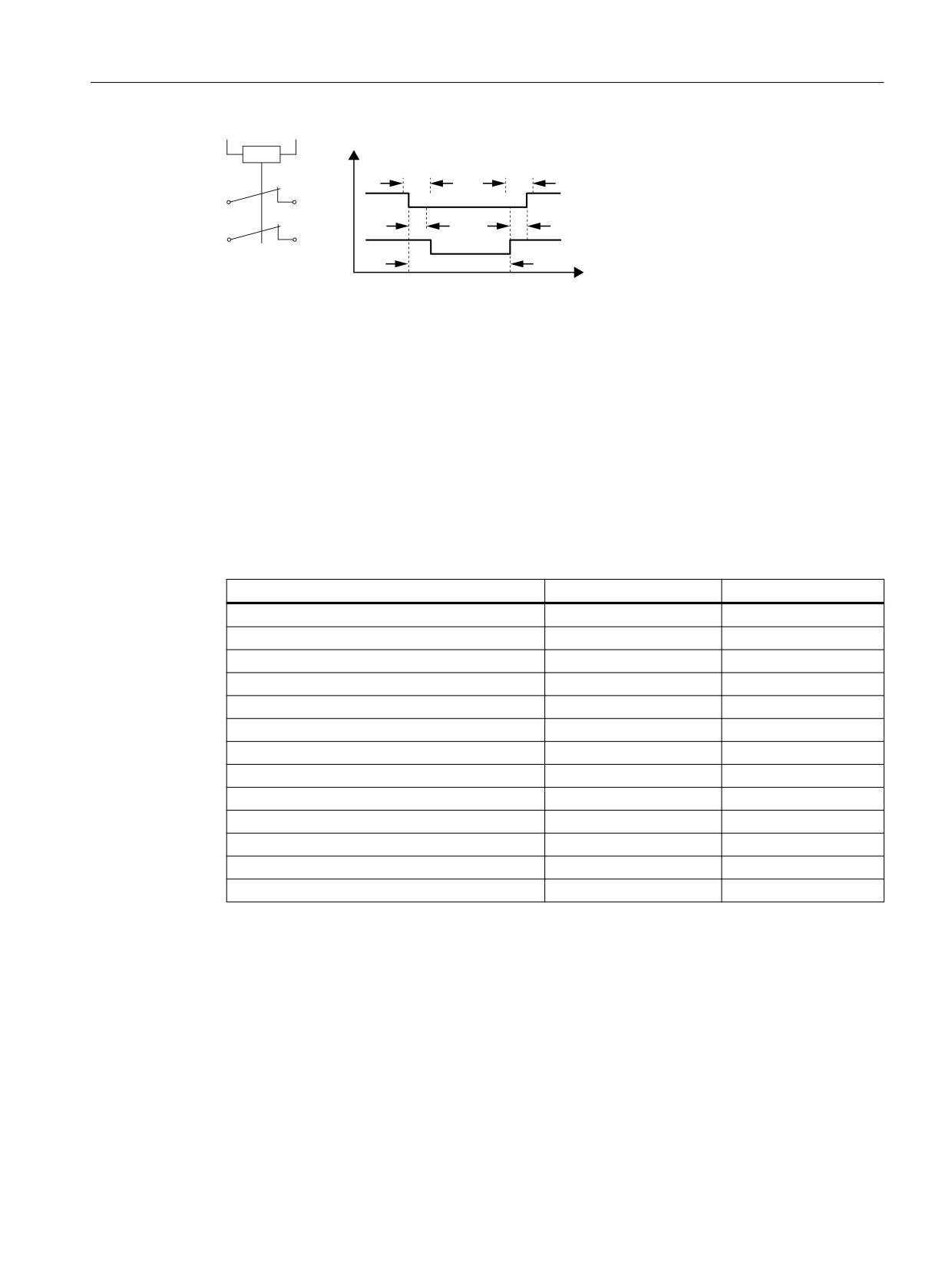
Control of the safety functions
6.6 Control of the Extended/Advanced Functions via F-DI (for CU310-2)
7'
7'
75
75
6ZLWFKLQJ LQWHUYDO
76
W
7R EH PDLQWDLQHG
76
!
7'
!
75
TS
Switching interval
TD
Discrepancy time
TR
Response time
Figure 6-7
Discrepancy time
6.6.1
Assigning Safety Integrated Functions to the F-DI/TM54F
The following table provides you with an overview of which Safety Integrated functions you can
control with which F-DI/F-DO (onboard or TM54F).
Table 6-18
Assigning Safety Integrated functions to F-DI/F-DO (onboard or TM54F)
Safety function
Onboard F-DI/F-DO
TM54F F-DI/F-DO
STO
x
x
SS1
x
x
SOS
x
x
SS2
x
x
SS2E
-
-
SLS
x
x
SSM1)
x
x
SDI
x
x
SLP
x
x
SCA
-
-
SLA
-
-
SP
-
-
Safe gearbox stage switchover
-
-
1)
As feedback signal in S_ZSW1 and S_ZSW2
6.6.2
F-DI function
6.6.2.1
Description
Failsafe digital inputs (F-DI) consist of 2 digital inputs. At the 2nd digital input, the cathode (M)
of the optocoupler is additionally brought out to enable connection of an output of an failsafe
control grounded through a switch. (The anode must be connected to 24 V DC.)
Safety Integrated
Function Manual, 06/2020, 6SL3097-5AR00-0BP3
249
Control of the safety functions
6.6 Control of the Extended/Advanced Functions via F-DI (for CU310-2)
Parameter p10040 is used to determine whether an F-DI is operated as NC/NC or NC/NO
contact. The status of each DI can be read at parameter r10051. The same bits of both drive
objects are logically linked by AND operation and return the status of the relevant F-DI.
Test signals from F-DOs and interference pulses can be filtered out using the input filter
(p10017), so that they do not cause any faults.
Explanation of terms:
NC contact / NC contact: To select the safety function, a "zero level" must be present at both
inputs.
NC contact / NO contact: To select the safety function, a "zero level" must be present at input
1 and a "1 level" at input 2.
The signal states at the two associated digital inputs (F-DI) must assume the same status
configured in p10040 within the monitoring time set in p10002.
The digital inputs of the CU310-2 cannot be dynamized by a test stop.
Table 6-19
Overview of the failsafe inputs in the SINAMICS S120/S150 List Manual:
Module
Function diagram
Inputs
CU310-2
2870
F-DI 0 ... 2
6.6.2.2
F-DI features
● Failsafe configuration with 2 digital inputs per F-DI
● Input filter to block test signals with an adjustable suppression time (p10017), see Chapter
"Bit pattern test (Page 214)".
● Configurable connection of NC/NC or NC/NO contacts by means of parameter p10040
● Status parameter r10051
Safety Integrated
250
Function Manual, 06/2020, 6SL3097-5AR00-0BP3
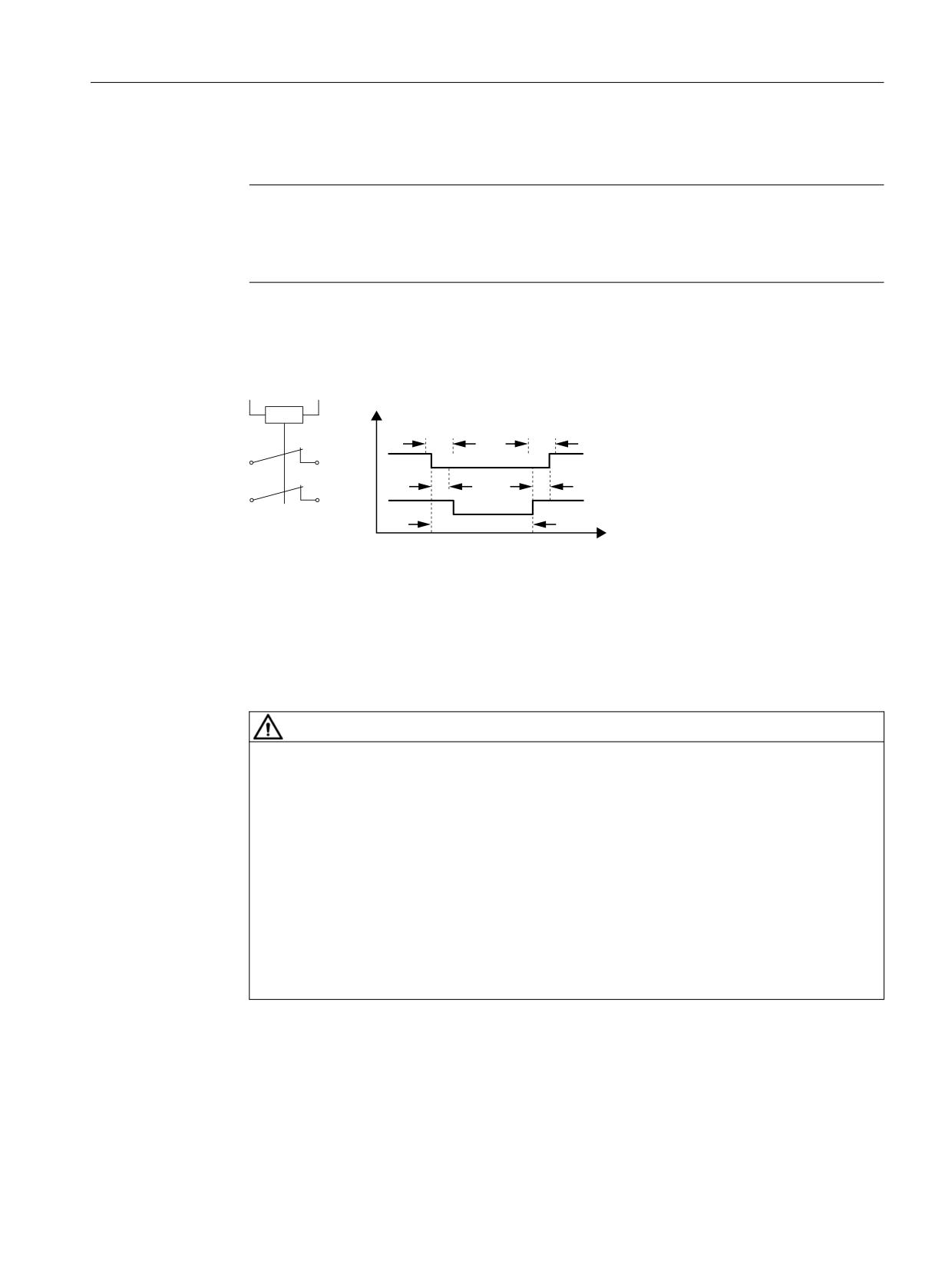
Control of the safety functions
6.6 Control of the Extended/Advanced Functions via F-DI (for CU310-2)
● Adjustable time window for monitoring discrepancy at both digital inputs by means of
parameter p10002 for all F-DIs
Note
Discrepancy time
To avoid incorrect triggering of fault messages, at these inputs the discrepancy time must
always be set less than the shortest time between 2 switching events (ON/OFF, OFF/ON).
Further notes for setting the discrepancy time (also see the following diagram "Discrepancy
time") are provided in the "SINAMICS S120/S150 List Manual" for the following message:
- F01611 (Basic Functions)
- C01770 (Extended/Advanced Functions)
7'
7'
75
75
6ZLWFKLQJ LQWHUYDO 76
W
7R EH PDLQWDLQHG
76
!
7'
!
75
TS
Switching interval
TD
Discrepancy time
TR
Response time
Figure 6-8
Discrepancy time
● 2nd digital input with additional tap of the optocoupler cathode for connecting an output of
a failsafe control grounded through a switch.
WARNING
Unwanted movement due to incorrect signal states as a result of diagnostic currents in the
switched-off state (logical state "0" or "OFF")
Unlike mechanical switching contacts, e.g. emergency stop switches, diagnostic currents
can also flow when the semiconductor is in the switched-off state. If interconnection with
digital inputs is faulty, the diagnostic currents can result in incorrect switching states.
Incorrect signal states of digital inputs can cause unwanted movements of machine parts
and result in serious injury or death.
● Observe the conditions of digital inputs and digital outputs specified in the relevant
manufacturer documentation.
● Check the conditions of the digital inputs and digital outputs with regard to currents in
the "OFF" state and if necessary connect the digital inputs to suitably dimensioned,
external resistors to protect against the reference potential of the digital inputs.
More information on this topic is available on the Internet at:
Parameterizing and configuring safety hardware (https://support.industry.siemens.com/cs/ww/
en/view/39700013)
Safety Integrated
Function Manual, 06/2020, 6SL3097-5AR00-0BP3
251
Control of the safety functions
6.6 Control of the Extended/Advanced Functions via F-DI (for CU310-2)
6.6.2.3
Function diagrams and parameters
Function diagrams (see SINAMICS S120/S150 List Manual)
●
2870
SI functions - CU310-2 (F-DI 0 ... F-DI 2)
Overview of important parameters (see SINAMICS S120/S150 List Manual)
● p10002
SI Motion F-DI switchover discrepancy time (CPU 1)
● p10017
SI Motion digital inputs debounce time (CPU 1)
● p10040
SI Motion, F-DI input mode (CPU 1)
● r10051.0...2
CO/BO: SI Motion digital inputs status (CPU 1)
6.6.3
Function of the F-DO
6.6.3.1
Description
The failsafe digital output (F-DO) comprises 2 digital outputs plus one digital input that checks
the switching state for forced checking procedure (test stop). The 1st digital output switches 24
V DC, and the 2nd switches M of the X130 (CU310-2) voltage supply.
The status of each F-DO can be read at parameter r10052. The status of the associated DI22
can be read using parameter r0722.22.
The actuator connected to the F-DO can also be tested under specific conditions as part of
forced checking procedure (test stop). See Chapter "Forced checking procedure (test stop) of
the CU310-2 (Page 308)".
Table 6-20
Overview of the failsafe outputs in the SINAMICS S120/S150 List Manual:
Module
Function diagram
Outputs
Associated checking in-
puts
CU310-2
2873
F-DO 0
DI 22
F-DO features
● Each F-DO with failsafe configuration consisting of 2 digital outputs plus one digital input for
checking the switching state for the forced checking procedure (test stop)
● Status parameters r10051/r10052
Safety Integrated
252
Function Manual, 06/2020, 6SL3097-5AR00-0BP3
Control of the safety functions
6.6 Control of the Extended/Advanced Functions via F-DI (for CU310-2)
Note
Display using r0747.16
If digital outputs DO16+ and DO16- act as F-DO, parameter r0747 "CU, digital outputs status",
bit 16 "DO 16 (- / X130.7, 8)" does not display the level defined by Safety Integrated. Instead,
it displays the ineffective setpoint state according to BICO signal source p0746 "BI: CU signal
source for terminal DO 16".
6.6.3.2
Signal sources for the F-DO
For the CU310-2, the following signals are available for interconnecting (p10042, ..., p10045)
on the F-DO:
● STO active
● SS1 active
● SS2 active
● SOS active
● SLS active
● SSM feedback active
● Safe State
● SOS selected
● Internal event
● Active SLS level bit 0
● Active SLS level bit 1
● SDI positive active
● SDI negative active
● SLP active
● Active SLP area
For the F-DO, up to 6 signals can be interconnected via indexes (p10042[0...5]); these are then
output AND'ed.
6.6.3.3
Safe state signal selection
For the CU310-2, the following (Safe State) signals can be requested via p10039[0...3]:
● STO active (power removed/pulses suppressed)
● SS1 active
● SS2 active
● SOS active
● SLS active
Safety Integrated
Function Manual, 06/2020, 6SL3097-5AR00-0BP3
253
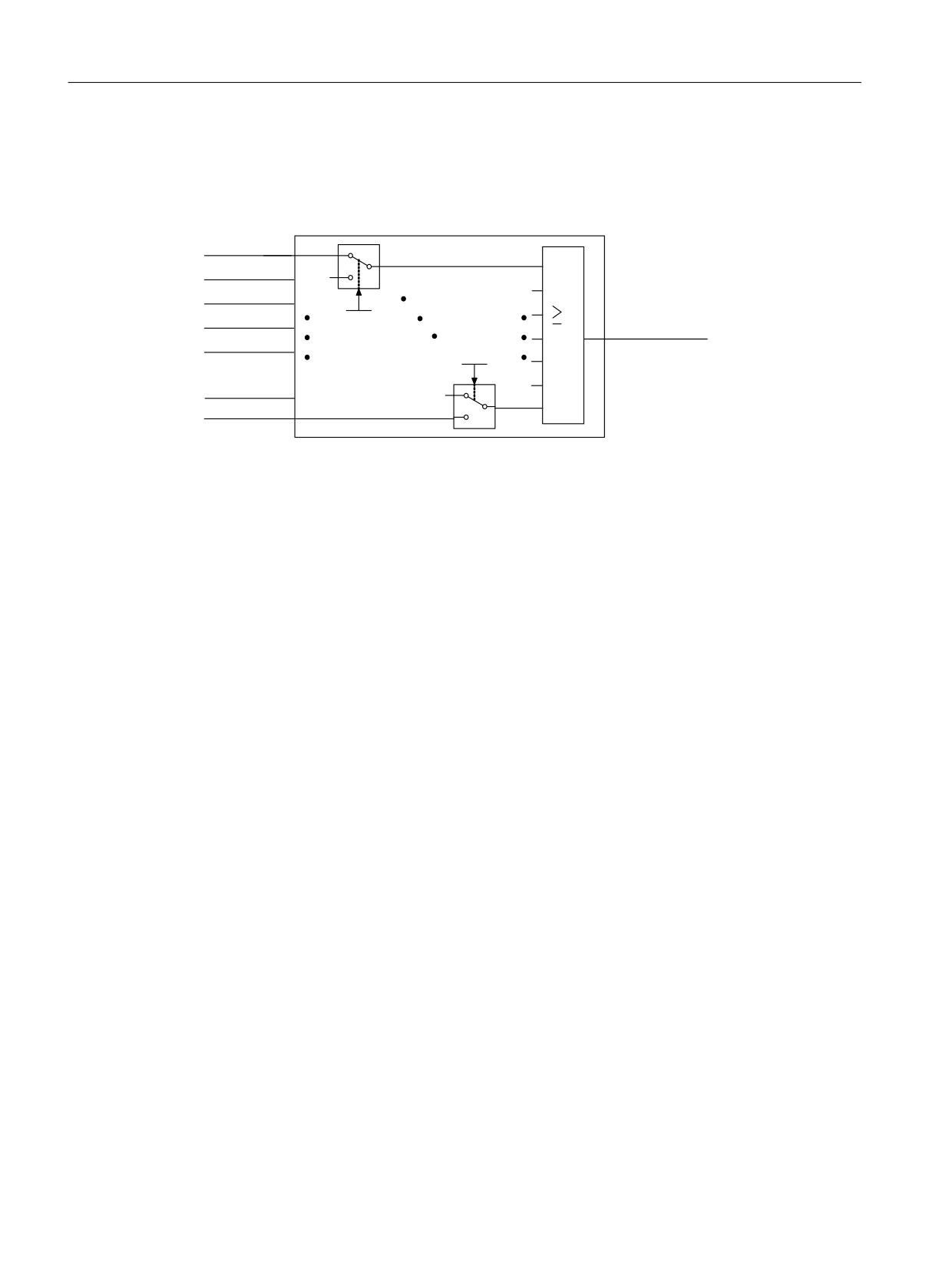
Control of the safety functions
6.6 Control of the Extended/Advanced Functions via F-DI (for CU310-2)
● SDI positive active
● SDI negative active
● SLP active
3XOVHV VXSSUHVVHG
66 DFWLYH
66
DFWLYH
626 DFWLYH
S
>[@
6DIH VWDWH
6/6 DFWLYH
S
>[@
6', SRVLWLYH DFWLYH
6', QHJDWLYH DFWLYH
6/3 DFWLYH
Figure 6-9
Safe state selection
The same signals (high-active) are logically AND'ed. The different signals selected via p10039
are logically OR'ed. Result of these logic operations is the "Safe State". Details can be found
in function block diagram 2876, see SINAMICS S120/S150 List Manual.
6.6.3.4
Function diagrams and parameters
Function diagrams (see SINAMICS S120/S150 List Manual)
●
2870
SI functions - CU310-2 (F-DI 0 ... F-DI 2)
●
2873
SI functions CU310-2 failsafe digital output (F-DO 0)
●
2875
SI functions - CU310-2 control interface
●
2876
SI functions - CU310-2 safe state selection
●
2877
SI functions, CU310-2 assignment (F-DO 0)
Overview of important parameters (see SINAMICS S120/S150 List Manual)
● p10039
SI Safe State signal selection (CPU 1)
● p10042[0...5]
SI F-DO 0 signal sources
● r10051.0...2
CO/BO: SI Digital inputs status (CPU 1)
● r10052.0
CO/BO: SI Digital output status (CPU 1)
Safety Integrated
254
Function Manual, 06/2020, 6SL3097-5AR00-0BP3

Control of the safety functions
6.7 Motion monitoring without selection
6.7
Motion monitoring without selection
As an alternative to controlling via terminals and/or PROFIsafe, there is also the option to
parameterize several Safety functions without selection. For this mode, after parameterization
and a POWER ON, these functions are permanently selected.
Example
"SLS without selection" can be used to monitor the maximum velocity, for example. This
monitoring function prevents the drive from exceeding a mechanical speed limit. When using
the "without selection" function, you do not have to use an F-DI and you do not have to use an
F-CPU.
Features
● The function "Motion monitoring without selection" is available in the following versions:
p9601
Meaning
Scope of functions
Comment
0024
Drive-integrated motion monitoring
● SLS
● p9501.0 = 1
hex
functions without selection are ena-
● SDI
● p9501.17 = 1
bled
0025
Drive-integrated motion monitoring
● SLS
● p9501.0 = 1
hex
functions without selection with STO
● SDI
● p9501.17 = 1
via terminals are enabled
● STO
● Basic Functions
● SS1
● Basic Functions
● SBC
● Basic Functions
● The functions "SLS without selection" and "SDI without selection positive/negative" are
selected with p9512.
● The functions without selection are available in the versions "with encoder" and "without
encoder" (selection via p9506).
● The functions without selection are parameterized and enabled in the same way as the
versions with control via PROFIsafe/terminals.
Acknowledging safety faults
Carefully observe the following cases for acknowledging Safety faults:
● Motion monitoring functions without selection integrated in the drive
Acknowledging Safety faults is only possible with POWER ON.
● Motion monitoring functions without selection integrated in the drive and Basic Functions via
onboard terminals
Acknowledging safety faults is possible with POWER ON or selecting/deselecting STO SS1
(see "Extended acknowledgment" in Chapter "Safe Torque Off (STO) (Page 76)").
Safety Integrated
Function Manual, 06/2020, 6SL3097-5AR00-0BP3
255